1
Table of Contents
1.
GENERAL INTRODUCTION.......................................................................4
1.1.
5V Encoder Signal Wiring .....................................................................8
1.1.1.
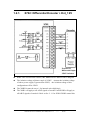
X702: Differential Encoder & Int_5V ...........................................9
1.1.2.
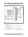
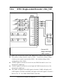
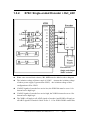
X702: Single-ended Encoder + Int_5V........................................10
1.1.3.
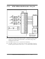
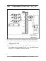
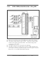
X702: Differential Encoder + Ext_5V.........................................11
1.1.4.
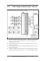
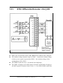
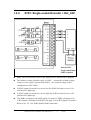
X702: Single-ended Encoder + Ext_5V ......................................12
1.1.5.
X703: Differential Encoder + Int_5V ..........................................13
1.1.6.
X703: Single-ended Encoder + Int_5V........................................14
1.1.7.
X703: Differential Encoder + Ext_5V.........................................15
1.1.8.
X703: Single-ended Encoder + Ext_5V ......................................16
1.2.
12V Encoder Signal .............................................................................17
1.2.1.
X702: Differential Encoder + Ext_12V.......................................18
1.3.
1.4.
1.5.
1.6.
2.
1.2.2.
X702: Single-ended Encoder + Ext_12V ....................................19
1.2.3.
X703: Differential Encoder + Ext_12V.......................................20
1.2.4.
X703: Single-ended Encoder + Ext_12V ....................................21
24V Encoder Signal .............................................................................22
1.3.1.
X702: Differential Encoder + Ext_24V.......................................23
1.3.2.
X702: Single-ended Encoder + Ext_24V ....................................24
1.3.3.
X703: Differential Encoder + Ext_24V.......................................25
1.3.4.
X703: Single-ended Encoder + Ext_24V ....................................26
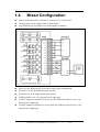
Mixed Configuration............................................................................27
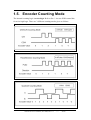
Encoder Counting Mode ......................................................................29
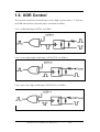
XOR Control........................................................................................30
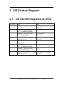
I/O CONTROL REGISTER.............................................................................33
2.1.
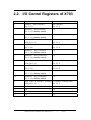
I/O Control Registers of X702.............................................................33
2.1.1.
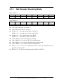
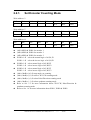
Set Encoder Counting Mode........................................................34
2.1.2.
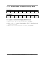
Read A/B/Z & Encoder Counting Mode......................................35
2.1.3.
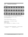
Encoder1 24-bit Value..................................................................36
2.1.4.
Encoder2 24-bit Value..................................................................37
2.2.
I/O Control Registers of X703.............................................................38
2.2.1.
Set Encoder Counting Mode........................................................39
2.2.2.
Read A/B/Z & Encoder Counting Mode......................................40
2.2.3.
Encoder1 24–bit Value.................................................................41
2.2.4.
Encoder2 24–bit Value.................................................................42
2.2.5.
Encoder3 24–bit Value.................................................................43
X702/X703 User’s Manual, Nov/2004, Rev. 1.0
------
2/59