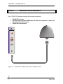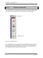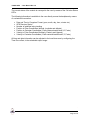
1
1769HP-GPS
USER MANUAL
Rev 1.1 – June 2005
1769HP-GPS - User Manual Rev 1.0
Table of Contents
Chapter 1
Chapter 2
Chapter 3
Chapter 4
Chapter 5
Chapter 6
Chapter 7
Introduction.......................................................................................................3
Module Accessories .........................................................................................4
Module Operation.............................................................................................5
Installing the Module ........................................................................................7
Configuring the Module ....................................................................................8
I/O Address Map ............................................................................................15
Module Status ................................................................................................22
Appendix A
Appendix B
Appendix C
Appendix D
Appendix E
PLC Ladder Example .....................................................................................23
Specifications .................................................................................................44
GPS Operation...............................................................................................45
Time standards ..............................................................................................49
Glossary .........................................................................................................50
.
Page 2 of 51
1769HP-GPS - User Manual Rev 1.0
CHAPTER 1
INTRODUCTION
The 1769HP-GPS module provides accurate time and position information and services
for the Allen-Bradley 1769 platform (CompactLogix or MicroLogix 1500).
The module makes use of Global Positioning System (GPS) technology to derive accurate
time which is synchronized with the atomic clocks located on the GPS satellites.
This document serves to describe the functionality, installation, configuration and use of
the module.
.
Page 3 of 51
1769HP-GPS - User Manual Rev 1.0
CHAPTER 2
MODULE ACCESSORIES
Each 1769HP-GPS package includes the following components:
G P S
•
•
•
•
1769HP-GPS module
5m RG58 patch lead with a SMA male and TNC male connector on either end
3.3V active 50Ω bullet antenna
1769HP-GPS user manual
MODULE
GPS
GPS
G lobal
P ositioning
& Tim ing
Module
ANT
Figure 2.1 : 1769HP-GPS module with antenna and patch-lead
.
Page 4 of 51
1769HP-GPS - User Manual Rev 1.0
MODULE OPERATION
CHAPTER 3
The 1769HP-GPS module is designed to operate within the Allen-Bradley 1769 backplane.
All power required for the module’s operation is derived from the 1769 backplane.
G P S
MODULE
Status LEDs
GPS
GPS
G lobal
P ositioning
& Tim ing
Module
SMA Antenna Port
ANT
Figure 3.1 : 1769HP-GPS Layout
The on-board GPS receiver is connected via the external SMA antenna port and external
antenna patch-lead to the active GPS antenna. Once the module is powered-up it will
begin searching for available GPS satellites. Soon after lock on at least 4 satellites has
been achieved the module’s internal time will become valid.
.
Page 5 of 51
1769HP-GPS - User Manual Rev 1.0
The current status of the module is conveyed to the user by means of the 2 bi-color Status
LED’s.
The following information is available to the user directly across the backplane by means
of a scheduled connection:
•
•
•
•
•
•
•
Date and Time in Gregorian Format (year, month, day, hour, minute etc.)
GPS Receiver Status
Number of satellites being tracking
Position in Polar Coordinates (latitude, longitude and altitude)
Position in Cartesian Coordinates ( Earth-centered-earth-fixed X,Y,Z axis)
Velocity in Polar Coordinates (Northerly, Easterly and Upward)
Velocity in Cartesian Coordinates ( Earth-centered-earth-fixed X,Y,Z axis)
All time and date information can be adjusted to the local time-zone by configuring the
Time-Zone offset, in the scheduled output image.
.
Page 6 of 51
1769HP-GPS - User Manual Rev 1.0
CHAPTER 4
INSTALLING THE MODULE
GPS utilizes a spread spectrum signal in the 1.5GHz range, and thus cannot penetrate
conductive or opaque surfaces. Thus the antenna should be mounted in a horizontal
position with an unobstructed view of the sky.
Attach the antenna patch lead to the antenna. It is recommended that waterproofing tape
be used to seal the connection.
NOTE: Should a longer patch lead be required it is recommended that a GPS signal
booster is used. Contact your local Hiprom Technologies distributor for assistance.
Attach the patch lead SMA (male) to the module’s SMA (female) connector. It is not
recommended that the antenna patch lead exceed a total loss of 10dB at 1.5GHz, as this
may increase the time to GPS lock, or in extreme cases, prevent GPS lock from being
achieved at all.
Once the module has been power up for the first time, it will search for satellites from a
cold start (i.e no almanac). The module will take approximately 5 minutes to acquire Lock.
Once a complete almanac has been downloaded, the time to achieve fix will be reduced to
around 45 seconds.
.
Page 7 of 51
1769HP-GPS - User Manual Rev 1.0
CHAPTER 5
CONFIGURING THE MODULE
The 1769HP-GPS module is supported by Allen Bradley’s MicroLogix 1500 and
CompactLogix PLC systems. Because the CompactLogix uses RSLogix 5000 and the
MicroLogix 1500 uses RSLogix 500, two different setup procedures are explained below.
5.1
CompactLogix (RSLogix 5000)
A direct connection between the controller and the 1769HP-GPS module is required to
transfer I/O data to and from the module. In addition the module supports various
unconnected messages that can be used to retrieve particular information.
Establishing the Direct Connection
This section describes the procedures necessary to configure the 1769HP-GPS module
within the CompactLogix system.
The 1769 Generic Module is used in RSLogix5000 to configure the module. The
configuration of the module is detailed in the table below.
CommFormat
Description
Input
Output
Configuration
Data Format
Data – INT
Connection parameters
Instance
101
100
102
Size
19
4
0
Table 5.1 : 1769HP-GPS connection parameters.
Request Packet Interval
RPI
1 ms
Table 5.2 : Local CompactBus connection parameters.
The steps required to add a new 1769HP-GPS module are detailed below.
.
Page 8 of 51
1769HP-GPS - User Manual Rev 1.0
Figure 5.1 : Right-click on I/O Configuration and select New Module
Figure 5.2 : Select Generic 1769 Module ( 1769HP-GPS MODULE )
.
Page 9 of 51
1769HP-GPS - User Manual Rev 1.0
Figure 5.3 : Configure module’s parameters
Figure 5.4 : Right-click on CompactBus Local and select Properties
.
Page 10 of 51
1769HP-GPS - User Manual Rev 1.0
Figure 5.5 : Configure CompactBus module’s RPI (Requested Packet Interval)
Once a modules configuration data has been downloaded to the controller, it will attempt
to establish a connection with the module. A connection will fail if there is inappropriate
configuration data.
.
Page 11 of 51
1769HP-GPS - User Manual Rev 1.0
5.2
MicroLogix 1500 (RSLogix 500)
A direct connection between the controller and the 1769HP-GPS module is required to
transfer I/O data to and from the module.
Establishing the Direct Connection
This section describes the procedures necessary to configure the 1769HP-GPS module
within the MicroLogix 1500 system.
Figure 5.6 : Right-click on I/O Configuration and select Open
.
Page 12 of 51
1769HP-GPS - User Manual Rev 1.0
Figure 5.6 : Left-click on Read I/O Config
Before the IO can be read, a connection must be established between RSLogix and the
PLC system (Micrologix 1500).
Figure 5.7 : Left-click on Read I/O Config
.
Page 13 of 51
1769HP-GPS - User Manual Rev 1.0
Figure 5.8 : Confirmation that the 1769HP-GPS module has been identified
.
Page 14 of 51
1769HP-GPS - User Manual Rev 1.0
I/O ADDRESS MAP
CHAPTER 6
The input and output image of the 1769HP-GPS module is defined in the following
sections. Appendix A and B provide example code and recommended structures that can
be used to extract and view the data.
5
4
3
2
1
0
SKY
6
LOC
7
RSV
SV Count
8
PPS
9
PDP
10
BAT
11
ANT
12
RSV
13
DTV
14
PEC
0
1
2
3
4
5
6
7
8
9
10
11
12
13
14
15
16
17
18
15
EWH
Word
NSH
Input Image
Milliseconds
Seconds
Minutes
Hours
Day
Month
Year
Latitude (Sec x 100)
Latitude (Minutes)
Longitude (Sec x 100)
Longitude (Minutes)
Altitude (1 x meters)
Altitude (10,000 x meters)
Velocity North (m/s x 10)
Velocity East (m/s x 10)
Velocity Up (m/s x 10)
Channel
SV PRN
Pos X (1 x meters)
Pos X (10,000 x meters)
Pos Y (1 x meters)
Pos Y (10,000 x meters)
Pos Z (1 x meters)
Pos Z (10,000 x meters)
Velocity X (m/s x 10)
Velocity Y (m/s x 10)
Velocity Z (m/s x 10)
SV Signal Strength
Reserved
Figure 6.1 : Connected Input Image
.
Page 15 of 51
1769HP-GPS - User Manual Rev 1.0
Input Image Description
Field/Value
SKY
Description
Visible Sky
0 = Sky not visible or no satellite signals
present
1 = Satellite signals available
No sky usually indicates that the antenna does not have a clear view of
the sky, such as in a building, etc.
LOC
Satellite Lock
0 = Not tracking sufficient satellites to provide positional
fix
1 = Sufficient satellites being tracked to provide
positional fix
Location
Type
CompactLogix:
Local:s:I.Data[0].0
MicroLogix 1500:
I:e.0/0
BIT
CompactLogix:
Local:s:I.Data[0].1
BIT
MicroLogix 1500:
I:e.0/1
Typically, tracking 4 satellites is sufficient to provide lock.
CompactLogix:
Local:s:I.Data[0].2
RSV
Reserved for future use
PPS
Pulse per Second
This bit transitions from 0 to 1 precisely every second.
The pulse duty cycle is approximately 50%.
PDP
PDOP OK
0 = Position Dilution of Precision is unacceptable
1 = No Position Dilution of Precision present
Position Dilution of Precision occurs when although there are sufficient
satellites in lock, 2 or more of them appear to occupy similar positions in
the sky and thus the number of effective satellites is decreased.
Battery Backup on Boot
0 = No battery backup available on boot-up.
1 = Battery backup available on boot-up.
BAT
ANT
With battery backup enabled the time taken for the GPS module to
regain satellite lock is greatly reduced.It is recommended that if the
module is not to be used for an extended period that the battery backup
be disabled.
Antenna OK
0 = Antenna Fault
1 = Antenna OK
An Antenna fault will occur if the antenna is not present or has been
damaged.
RSV
BIT
MicroLogix 1500:
I:e.0/2
Reserved for future use
CompactLogix:
Local:s:I.Data[0].3
BIT
MicroLogix 1500:
I:e.0/3
CompactLogix:
Local:s:I.Data[0].4
MicroLogix 1500:
I:e.0/4
BIT
CompactLogix:
Local:s:I.Data[0].5
MicroLogix 1500:
I:e.0/5
BIT
CompactLogix:
Local:s:I.Data[0].6
BIT
MicroLogix 1500:
I:e.0/6
CompactLogix:
Local:s:I.Data[0].7
BIT
MicroLogix 1500:
I:e.0/7
.
Page 16 of 51
1769HP-GPS - User Manual Rev 1.0
DTV
SV Count
PEC
Date / Time Valid
0 = Date Time Not Valid
1 = Date Time synchronized with GPS
Satellite count
Number of Satellites currently being tracked
Last Position Vector in ECEF Mode
0 = Position Update in Latitude, Logtitude and Altitude format
1 = Position Update in Earth-Centred-Earth-Fixed X,Y,Z format
ECEF Mode can be invoked by setting the ECF bit in the output
image. (MicroLogix 1500: O:e.0/1 or CompactLogix:
Local:s:O.Data[0].1)
EWH
Current East / West Hemisphere
0 = Current position in East hemishere
1 = Current position in West hemisphere
This flag is Not valid when in ECEF mode is invoked.
NSH
Current North / South Hemisphere
0 = Current position in North hemishere
1 = Current position in South hemisphere
This flag is Not valid when in ECEF mode is invoked.
Milliseconds
Seconds
Minutes
Hours
Day
Real Time Milliseconds
Current real time Milliseconds ( 0 - 999 )
Real Time Seconds
Current real time Seconds ( 0 - 59 )
CompactLogix:
Local:s:I.Data[0].8
BIT
MicroLogix 1500:
I:e.0/8
CompactLogix:
Local:s:I.Data[0].9-12
BIT
MicroLogix 1500:
I:e.0/9-12
CompactLogix:
Local:s:I.Data[0].13
BIT
MicroLogix 1500:
I:e.0/13
CompactLogix:
Local:s:I.Data[0].14
BIT
MicroLogix 1500:
I:e.0/14
CompactLogix:
Local:s:I.Data[0].15
BIT
MicroLogix 1500:
I:e.0/15
CompactLogix:
Local:s:I.Data[1]
INT
MicroLogix 1500:
I:e.1
CompactLogix:
Local:s:I.Data[2]
INT
MicroLogix 1500:
I:e.2
Real Time Minutes
Current Local time Minutes ( 0 - 59 )
CompactLogix:
Local:s:I.Data[3]
This is dependent on the configured time zone (MicroLogix 1500: O:e.1
or CompactLogix: Local:s:O.Data[1])
MicroLogix 1500:
I:e.3
Real Time Hours
Current Local time Hours ( 0 - 23 )
CompactLogix:
Local:s:I.Data[4]
This is dependent on the configured time zone (MicroLogix 1500: O:e.1
or CompactLogix: Local:s:O.Data[1])
MicroLogix 1500:
I:e.4
INT
INT
Calendar Day of Month
Current Local Calendar Day ( 1 - 31 )
CompactLogix:
Local:s:I.Data[5]
INT
This is dependent on the configured time zone (MicroLogix 1500: O:e.1
.
Page 17 of 51
1769HP-GPS - User Manual Rev 1.0
Month
Year
Latitude
(PEC = 0)
or CompactLogix: Local:s:O.Data[1])
MicroLogix 1500:
I:e.5
Calendar Month
Current Local Calendar Month ( 1 - 12 )
CompactLogix:
Local:s:I.Data[6]
This is dependent on the configured time zone (MicroLogix 1500: O:e.1
or CompactLogix: Local:s:O.Data[1])
MicroLogix 1500:
I:e.6
Calendar Year
Current Local Calendar Year
CompactLogix:
Local:s:I.Data[7]
This is dependent on the configured time zone (MicroLogix 1500: O:e.1
or CompactLogix: Local:s:O.Data[1])
MicroLogix 1500:
I:e.7
INT
Current Position Latitude
Degrees = integer (I:e.9 / 60)
Minutes = I:e.9 mod 60
Seconds = I:e.8 / 100
Only Valid if the PEC flag (I:e.0/13) = 0
OR
Distance from Earth-centre along the X - axis.
X-Position = (I:e.8 + ( I:e.9 x 10,000)) in metres
Position X
(PEC = 1)
INT
CompactLogix:
Local:s:I.Data[8] – [9]
MicroLogix 1500:
I:e.8-9
INT
Position is calculated with respect to the WGS-84 Earth-Centred
Earth-Fixed co-ordinate system. The X-axis is defined as the vector with
origin at the earth's centre and passing through the intersection of the
equator and Greenwich meridian.
Only Valid if the PEC flag (I:e.0/13) = 1
Longitude
(PEC = 0)
Current Position Longitude
Degrees = integer (I:e.11 / 60)
Minutes = I:e.11 mod 60
Seconds = I:e.10 / 100
Only Valid if the PEC flag (I:e.0/13) = 0
OR
Distance from Earth-centre along the Y - axis.
Y-Position = (I:e.10 + ( I:e.11 x 10,000) in metres
Position Y
(PEC = 1)
CompactLogix:
Local:s:I.Data[10] –
[11]
INT
MicroLogix 1500:
I:e.10-11
Position is calculated with respect to the WGS-84 Earth-Centred EarthFixed co-ordinate system. The Y-axis is defined as the vector with origin
at the earth's centre and passing through the equator 90 degrees east
of the Greenwich meridian.
Only Valid if the PEC flag (I:e.0/13) = 1
Altitude
(PEC = 0)
Current Position Altiude
Altitude= (I:e.12 + ( I:e.13 x 10,000) in metres I:e.13
Only Valid if the PEC flag (I:e.0/13) = 0
OR
Position Z
(PEC = 1)
Distance from Earth-centre along the Y - axis.
Z-Position = (I:e.10 + ( I:e.11 x 10,000) in metres
CompactLogix:
Local:s:I.Data[12] –
[13]
INT
MicroLogix 1500:
I:e.12-13
Position is calculated with respect to the WGS-84 Earth-Centred Earth-
.
Page 18 of 51
1769HP-GPS - User Manual Rev 1.0
Fixed co-ordinate system. The Z-axis is defined as the vector with origin
at the earth's centre and passing through the North pole.
Only Valid if the PEC flag (I:e.0/13) = 1
Current Northerly Velocity
Velocity North / 10 (in m/s)
Velocity –
North
(PEC = 0)
Velocity – X
(PEC = 1)
Velocity –
East
(PEC = 0)
A negative value indicates a Southerly direction of movement.
Only Valid if the PEC flag (I:e.0/13) = 0
OR
CompactLogix:
Local:s:I.Data[14]
Speed with respect to the X - axis.
X-Velocity / 10.0 (in m/s)
MicroLogix 1500:
I:e.14
INT
The X-axis is defined as the vector with origin at the earth's centre
and passing through the intersection of the equator and Greenwich
meridian.
Only Valid if the PEC flag (I:e.0/13) = 1
Current Easterly Velocity
Velocity East / 10 (in m/s)
A negative value indicates a Westerly direction of movement.
Only Valid if the PEC flag (I:e.0/13) = 0
OR
CompactLogix:
Local:s:I.Data[15]
Speed with respect to the Y - axis.
Y-Velocity / 10.0 (in m/s)
MicroLogix 1500:
I:e.15
INT
Velocity – Y
(PEC = 1)
The Y-axis is defined as the vector with origin at the earth's centre
and passing through the intersection of the equator and Greenwich
meridian.
Only Valid if the PEC flag (I:e.0/13) = 1
Current Upward Velocity
Velocity Up / 10 (in m/s)
Velocity – UP
(PEC = 0)
Velocity – Z
(PEC = 1)
A negative value indicates a Downward direction of movement.
Only Valid if the PEC flag (I:e.0/13) = 0
OR
CompactLogix:
Local:s:I.Data[16]
Speed with respect to the Z - axis.
Z-Velocity / 10.0 (in m/s)
MicroLogix 1500:
I:e.16
The Z-axis is defined as the vector with origin at the earth's centre
and passing through the intersection of the equator and Greenwich
meridian.
Only Valid if the PEC flag (I:e.0/13) = 1
GPS Receiver Channel Number
These 3 bits indicate which of the GPS's 8 (0-7) channels' data is being
displayed.
Channel
SV PRN
INT
Because all 8 channels' data is passed with a single word, it is time
division multiplexed, showing a different channel every second. The
channel number can be used as an indirect addressing pointer, to store
the Channel SV PRN and Signal Strengths in the PLC.
Satellite Vehicle PRN Identification Number tracked on current
channel
Each operational GPS satellite has a unique PRN identification number
(0-31).
CompactLogix:
Local:s:I.Data[17].1315
INT
MicroLogix 1500:
I:e.17/13-15
CompactLogix:
Local:s:I.Data[17].812
INT
MicroLogix 1500:
I:e.17/8-12
.
Page 19 of 51
1769HP-GPS - User Manual Rev 1.0
Updated in conjuction with "Channel" described above
SV Signal
Strength
Reserved
Satellite Signal Strength on current channel
A measure of the satellite signal strength calculated during signal
correlation.
Signal Strength in (dbHz x 10 ) after correlation. Updated in conjuction
with "Channel" described above
CompactLogix:
Local:s:I.Data[17].0-7
INT
MicroLogix 1500:
I:e.17/0-7
CompactLogix:
Local:s:I.Data[18]
Reserved for future use
INT
MicroLogix 1500:
I:e.18
.
Page 20 of 51
1769HP-GPS - User Manual Rev 1.0
Output Image
15
14
13
12
11
0
1
2
3
10
9
8
7
6
5
4
3
2
1
0
ECF
WORD
Reserved
Time Zone (Hours x 10)
Reserved
Reserved
Figure 6.2 : Connected Output Image
Output Image Description
Field
ECF
Description
Select Earth-Centred-Earth-Fixed Mode
Setting this bit causes the module to report position and
velocity data in Cartesian co-ordinates.
Clearing this bit causes th./e module to report position and
velocity data in Polar co-ordinates.
Time zone
Reserved
Time Zone Configuration
Used to set the module to report in local time standard.
Time zone = UTC Offest where the UTC Offest is the
difference, in hours, between local time and GMT.
E.g. For Pacific Standard Time (GMT - 8) set time zone = 8
Reserved for future use
Location
Type
CompactLogix:
Local:s:O.Data[0].0
MicroLogix 1500:
O:e.0/0
BIT
CompactLogix:
Local:s:O.Data[1]
INT
MicroLogix 1500:
O:e.1
CompactLogix:
Local:s:O.Data[2] –
[3]
INT
MicroLogix 1500:
O:e.2 - 3
The Time zone needs to be copied from a tag (of type real) into the output word. Appendix
A and B provide example code and recommended data types.
.
Page 21 of 51
1769HP-GPS - User Manual Rev 1.0
MODULE STATUS
CHAPTER 7
The following sections describe the various status of the module and how they may be
determined via the 2 bi-color (Green / Red ) LEDs.
Status LEDs
LED
DESCRIPTION
Module
Module Status
GPS
GPS Lock Status
STATUS
Solid Red
Flashing Red
Flashing Green
Solid Green
Solid Red
Flashing Red
Flashing Green
Solid Green
MEANING
Major Hardware Fault
Major Fault
Minor Fault
Module operating correctly
Antenna Failure
No Satellite found
Busy acquiring satellites
Full GPS Lock, positioning and time
fixing
Table 8.1 : LED status information of the module.
.
Page 22 of 51
1769HP-GPS - User Manual Rev 1.0
APPENDIX A
PLC LADDER EXAMPLE
The 1769HP-GPS module is supported by Allen Bradley’s MicroLogix 1500 and
CompactLogix PLC systems. Thus ladder examples for RSLogix 500 and RSLogix 5000
are given below.
A.1.
RSLogix 500
The ladder example on the following pages consists of the following program files:
LAD 2 (Page: 23)
• Calls all other program files
LAD 3 – POSITION (Page 24-29)
• Extracts position in either Polar or ECEF format
LAD 4 – SIGNAL (Page 30 – 31)
• Extracts the satellite signal strengths for all 8 GPS receiver channels
LAD 5 – CONFIG (Page 32)
• Configures Time Zone
The following example code can be downloaded from the Hiprom website.
(www.hiprom.com)
.
Page 23 of 51
1769HP-GPS - User Manual Rev 1.0
.
Page 24 of 51
1769HP-GPS - User Manual Rev 1.0
.
Page 25 of 51
1769HP-GPS - User Manual Rev 1.0
.
Page 26 of 51
1769HP-GPS - User Manual Rev 1.0
.
Page 27 of 51
1769HP-GPS - User Manual Rev 1.0
.
Page 28 of 51
1769HP-GPS - User Manual Rev 1.0
.
Page 29 of 51
1769HP-GPS - User Manual Rev 1.0
.
Page 30 of 51
1769HP-GPS - User Manual Rev 1.0
.
Page 31 of 51
1769HP-GPS - User Manual Rev 1.0
.
Page 32 of 51
1769HP-GPS - User Manual Rev 1.0
.
Page 33 of 51
1769HP-GPS - User Manual Rev 1.0
A.2.
RSLogix 5000
This Appendix provides a detailed description of recommended data structures that can be
used in conjunction with the provided example ladder logic given below. The following
example code (and structures) can be downloaded from the Hiprom website.
(www.hiprom.com).
.
Page 34 of 51
1769HP-GPS - User Manual Rev 1.0
.
Page 35 of 51
1769HP-GPS - User Manual Rev 1.0
.
Page 36 of 51
1769HP-GPS - User Manual Rev 1.0
.
Page 37 of 51
1769HP-GPS - User Manual Rev 1.0
.
Page 38 of 51
1769HP-GPS - User Manual Rev 1.0
.
Page 39 of 51
1769HP-GPS - User Manual Rev 1.0
.
Page 40 of 51
1769HP-GPS - User Manual Rev 1.0
A.2.1.
Recommended Input Image Structures
Data of the 1769HP-GPS can be presented clearly by manipulating and copying the input
image to the GPS user-defined data type (UDT) structure. This structure utilizes the
following embedded UDT structures (detailed below)
• GPS_Status
• GPS_Satellite_Information
• GPS_Time
• GPS_Polar_Position
• GPS_Cartesian_Position
• GPS_Polar_Velocity
• GPS_Cartesian_Velocity
Name
Status
Sat_Info
Time
Polar_Position
Cartesian_Position
Polar_Velocity
Cartesian_Velocity
Temp
GPS
Data Type
GPS_Status
GPS_Satellite_Information
GPS_Time
GPS_Polar_Position
GPS_Cartesian_Postion
GPS_Polar_Velocity
GPS_Cartesian_Velocity
REAL[4]
Style
Decimal
Decimal
Decimal
Decimal
Decimal
Decimal
Decimal
Float
Table A.1 : GPS UDT
Name
SKY
LOC
DIFF
PPS
PDP
BAT
ANT
RSV
DTV
SVCOUNT
SVCOUNT1
SVCOUNT2
SVCOUNT3
PEC
EWH
NSH
GPS_Status
Data Type
BOOL
BOOL
BOOL
BOOL
BOOL
BOOL
BOOL
BOOL
BOOL
BOOL
BOOL
BOOL
BOOL
BOOL
BOOL
BOOL
Style
Decimal
Decimal
Decimal
Decimal
Decimal
Decimal
Decimal
Decimal
Decimal
Decimal
Decimal
Decimal
Decimal
Decimal
Decimal
Decimal
Table A.2 : GPS_Status UDT
.
Page 41 of 51
1769HP-GPS - User Manual Rev 1.0
GPS_Satellite_Information
Name
Data Type
SV_Count
INT
Channel
INT
SV PRN
INT
SV_Signal_Strength INT
Style
Decimal
Decimal
Decimal
Decimal
Table A.3 : GPS_Satellite_Information UDT
Name
MilliSecond
Second
Minute
Hour
Day
Month
Year
GPS_Time
Data Type
INT
INT
INT
INT
INT
INT
INT
Style
Decimal
Decimal
Decimal
Decimal
Decimal
Decimal
Decimal
Table A.4 : GPS_Time UDT
GPS_Polar_Position
Name
Data Type
Latitude_Degrees
INT
Latitude_Minutes
INT
Latitude_Seconds
REAL
Longtitude_Degrees
INT
Longtitude_Minutes
INT
Longtitude_Seconds
REAL
Altitude
REAL
Style
Decimal
Decimal
Float
Decimal
Decimal
Float
Float
Table A.5 : GPS_Polar_Position UDT
Name
X_Position
Y_Position
Z_Position
GPS_Cartesian_Position
Data Type
REAL
REAL
REAL
Style
Float
Float
Float
Table A.6 : GPS_Cartesian_Position UDT
.
Page 42 of 51
1769HP-GPS - User Manual Rev 1.0
Name
Northerly_Velocity
Easterly_Velocity
Upward_Velocity
GPS_Polar_Velocity
Data Type
INT
INT
INT
Style
Decimal
Decimal
Decimal
Table A.7 : GPS_Polar_Velocity UDT
Name
X_Velocity
Y_Velocity
Z_Velocity
GPS_Cartesian_Velocity
Data Type
INT
INT
INT
Style
Decimal
Decimal
Decimal
Table A.8 : GPS_Cartesian_Velocity UDT
.
Page 43 of 51
1769HP-GPS - User Manual Rev 1.0
APPENDIX B
SPECIFICATIONS
Parameter
Specification
General
Module Location
Backplane Current
RPI
General
Accuracy Horizontal
Altitude
Time
Hot Start
Warm Start
Cold Start
Antenna Connector
Frequency Range
Polarization
Output Impedance
VSWR
Axial Ratio
Gain
Out of Band Rejection
Azimuth Coverage
Elevation Coverage
Coax Type
Impedance
Any Slot
Electrical
165mA @ 5.0V
Schedules Connection Paramters
1ms to 750ms
GPS Receiver Specification
L1 frequency (1575.42 MHz), C/A code (Standard
Positioning Service), 8-channel, continuous tracking
receiver,
32 correlators
<6 meters (50%), <9 meters (90%)
<11 meters (50%), <18 meters (90%)
±1ms (±1 RPI)
<14 sec. (50%), <18 sec. (90%)
<38 sec. (50%), <45 sec. (90%)
<90 sec. (50%), <170 sec. (90%)
Active Antenna
SMA female connector
1575.42 MHz ± 1.023 MHz
Right-hand circular polarization (RHCP)
50Ω
2.0 maximum
90°: 4.0 dB maximum; 10°: 6 dB maximum
35 dB ± 3 dB
fo: 1575.42 MHz
fo ± 20 MHz : 7dB min
fo ± 30 MHz : 12dB min
fo ± 40 MHz : 20dB min
fo ± 100 MHz : 100dB min
360° (omni-directional)
0° to 90° elevation (hemispherical)
Antenna Patch Lead
RG-58
50Ω
.
Page 44 of 51
1769HP-GPS - User Manual Rev 1.0
APPENDIX C
GPS OPERATION
The Global Positioning System (GPS) is a satellite based navigation system operated and
maintained by the U.S. Department of Defence. The system consists of a constellation of
24 satellites providing world-wide, 24 hour, three dimensional (3D) coverage. Although
originally conceived for military needs, GPS has a broad array of civilian applications
including surveying, marine, land, aviation, and vehicle navigation. GPS is the most
accurate technology available for vehicle navigation.
C.1
4.2
GPS Satellite Message
Every GPS satellite transmits the Coarse/Acquisition (C/A) code and satellite data
modulated onto the L1 carrier frequency (1575.42 MHz). The satellite data transmitted by
each satellite includes a satellite almanac for the entire GPS system, its own satellite
ephemeris and its own clock correction.
The satellite data is transmitted in 30-second frames. Each frame contains the clock
correction and ephemeris for that specific satellite ,and two pages of the 50-page GPS
system almanac. The almanac is repeated every 12.5 minutes. The ephemeris is repeated
every 30 seconds. The system almanac contains information about each of the satellites in
the constellation, ionospheric data, and special system messages. The GPS system
almanac is updated weekly and is typically valid for months. The ephemeris contains
detailed orbital information for a specific satellite. Ephemeris data changes hourly, but is
valid for up to four hours. The GPS control segment updates the system almanac weekly
and the ephemeris hourly through three ground-based control stations. During normal
operation, the 1769HP-GPS receiver module updates its ephemeris and almanac as
needed. The performance of a GPS receiver at power-on is determined largely by the
availability and accuracy of the satellite ephemeris data and the availability of a GPS
system almanac.
C.2 Satellite Acquisition and Time to First Fix
4.3.1
Cold-Start
The term “cold-start” describes the performance of a GPS receiver at power-on when no
navigation data is available. “cold” signifies that the receiver does not have a current
almanac, satellite ephemeris, initial position, or time. The cold-start search algorithm
applies to a 1769HP-GPS receiver which has no memory of its previous session (i.e., is
powered on without the memory backup circuit connected to a source of DC power). This
is the “out of the box” condition of the GPS module as received from the factory. In a coldstart condition the receiver automatically selects a set of eight satellites and dedicates an
individual tracking channel to each satellite, to search the Doppler range frequency for
each satellite in the set. If none of the eight selected satellites is acquired after a
predetermined period of time (time-out), the receiver will select a new search set of eight
satellites and will repeat the process, until the first satellite is acquired. As satellites are
.
Page 45 of 51
1769HP-GPS - User Manual Rev 1.0
acquired, the receiver automatically collects ephemeris and almanac data. The GPS
receiver uses the knowledge gained from acquiring a specific satellite to eliminate other
satellites, those below the horizon, from the search set. This strategy speeds the
acquisition of additional satellites required to achieve the first position fix. The cold-start
search sets are established to ensure that at least three satellites are acquired within the
first two time-out periods. As soon as three satellites are found, the receiver will compute
an initial position fix. The typical time to first fix is less than 2 minutes. A complete system
almanac is not required to achieve a first position fix. However, the availability and
accuracy of the satellite ephemeris data and the availability of a GPS almanac can
substantially shorten the time to first fix.
4.3.2
Warm Start
In a warm-start condition the receiver has been powered down for at least one hour but
has stored a current almanac, an initial position, and time, in memory. When connected to
an external back-up power source (battery back-up), the 1769HP-GPS receiver retains the
almanac, approximate position, and time to aid in satellite acquisition and reduce the time
to first fix.
During a warm start, the 1769HP-GPS receiver identifies the satellites which are expected
to be in view, given the system almanac, the initial position and the approximate time. The
receiver calculates the elevation and expected Doppler shift for each satellite in this
expected set and directs the eight tracking channels in a parallel search for these
satellites. The warm start time to first fix, when the receiver has been powered down for
more than 60 minutes (i.e. the ephemeris data is old), is usually less than 45 seconds.
4.3.3
Hot Start
A hot start strategy applies when the 1769HP-GPS receiver has been powered down for
less than 60 minutes, and the almanac, position, ephemeris, and time are valid. The hot
start search strategy is similar to a warm start, but since the ephemeris data in memory is
considered current and valid, the acquisition time is typically less than 20 seconds.
C.3
4.4
Satellite Mask Settings
Once the 1769HP-GPS receiver has acquired and locked onto a set of satellites, which
pass the mask criteria listed in this section, and has obtained a valid ephemeris for each
satellite, it will output regular position, velocity and time reports according to the protocol
selected. The satellite masks used by the 1769HP-GPS receiver are listed in Table D.1.
These masks serve as the screening criteria for satellites used in fix computations and
ensure that position solutions meet a minimum level of accuracy. The 1769HP-GPS
receiver will only output position, course, speed and time when a satellite set can be
acquired which meets all of the mask criteria.
.
Page 46 of 51
1769HP-GPS - User Manual Rev 1.0
Parameter
Elevation
SnR
PDOP
Mask
>5°
>3
12
Table D.1 : Satellite Mask Limits
4.4.1
Elevation Mask
Satellites below a 5° elevation are not used in the position solution. Although low elevation
satellites can contribute to a lower/better PDOP, the signals from low elevation satellites
are poorer quality, since they suffer greater tropospheric and ionospheric distortion than
the signals from higher elevation satellites. These signals travel further through the
ionospheric and tropospheric layers. In addition, low elevation satellites can contribute to
frequent constellation switches, since the signals from these satellites are more easily
obscured by buildings and terrain. Constellation switches can cause noticeable jumps in
the position output. Since worldwide GPS satellite coverage is generally excellent, it is not
usually necessary to use satellites below a 5° elevation to improve GPS coverage time. In
some applications, like urban environments, a higher mask may be warranted to minimize
the frequency of constellation switches and the impact of reflected signals.
4.4.2
SNR Mask
Although the 1769HP-GPS receiver is capable of tracking signals with SNRs as low as 0,
the default SNR mask is set to 3 to eliminate poor quality signals from the fix computation
and minimize constellation switching. Low SNR values may result from:
• Low Elevation Satellites
• Partially Obscured Signals (e.g. Dense Foliage)
• Multi-Reflected Signals (Multi-Path)
The distortion of signals and the frequent constellation switches associated with lowelevation satellites were discussed above. In mobile applications, the attenuation of
signals by foliage is typically a temporary condition. Since the 1769HP-GPS receiver can
maintain lock on signals with SNRs as low as 0, it offers excellent performance when
traveling through heavy foliage. Multi-reflected signals, also known as Multi-path, can
degrade the position solution. Multi-path is most commonly found in urban environments
with many tall buildings and a preponderance of mirrored glass, which is popular in
modern architecture. Multi-reflected signals tend to be weak (low SNR value), since each
reflection attenuates the signal. By setting the SNR mask to 3 the impact of multi-reflected
signals is minimized.
4.4.3 DOP Mask
Position Dilution of Precision (DOP) is a measure of the error caused by the geometric
relationship of the satellites used in the position solution. Satellite sets which are tightly
clustered or aligned in the sky will have a high DOP and will contribute to a lower position
accuracy. For most applications, a DOP mask of 12 offers a satisfactory trade-off between
accuracy and GPS coverage time.
.
Page 47 of 51
1769HP-GPS - User Manual Rev 1.0
Position Accuracy
GPS position accuracy is degraded by atmospheric distortion, satellite geometry, satellite
clock errors, and receiver clock errors. Effective models for atmospheric distortion of
satellite signals have been developed to minimize the impact of tropospheric and
ionospheric effects. The impact of satellite clock errors is minimized by incorporating the
clock corrections transmitted by each satellite used in the position solution.
GPS Timing
In many timing applications, such as time/frequency standards, site synchronization
systems and event measurement systems, GPS receivers are used to discipline local
oscillators. The GPS constellation consists of 24 orbiting satellites. Each GPS satellite
contains a highly-stable atomic (Cesium) clock, which is continuously monitored and
corrected by the GPS control segment. Consequently, the GPS constellation can be
considered a set of 24 orbiting clocks with worldwide 24-hour coverage. GPS receivers
use the signals from these GPS “clocks” to correct its internal clock, which is not as stable
or accurate as the GPS atomic clocks. In addition to serving as a highly accurate standalone time source, GPS receivers are used to synchronize distant clocks in communication
or data networks. This synchronization is possible since all GPS satellite clocks are
corrected to a common master clock. Therefore, the relative clock error is the same,
regardless of which satellite or satellites are used. For timing applications requiring a
“common clock”, GPS is the ideal solution. The position and time errors are related by the
speed of light. Therefore, a position error of 100 meters corresponds to a time error of
approximately 333 ns.
.
Page 48 of 51
1769HP-GPS - User Manual Rev 1.0
APPENDIX D
TIME STANDARDS
There are many different time standards used in the world today. This chapter describes
the different formats and standards used in the 1769HP-GPS module and how the relate
to one another.
D.1 GPS Time
By synchronizing with the atomic clocks on GPS satellites the 1769HP-GPS module is
able to compute accurate GPS time. GPS time differs from UTC (Universal Coordinated
Time) by a variable integer number of seconds:
UTC = (GPS time) - (GPS UTC Offset)
As of April 2002, the GPS UTC offset was 13 seconds. The offset increases by 1 second
approximately every 18 months. The 1769HP-GPS module automatically acquires the
UTC offset from the received GPS system almanac and calculates the correct UTC.
The 1769HP-GPS receiver makes use of the Extended GPS Week Number as the
absolute number of weeks since the beginning of GPS time or January 6, 1980. Using this,
rather than the true GPS Week Number prevents any possible roll-over issues (similar to
Y2K), that earlier generation GPS receivers suffered from.
D.2 Universal Coordinate Time (UTC)
Universal Coordinate Time (UTC) is the world standard maintained by an ensemble of
atomic clocks operated by government organizations around the world. UTC time replaced
GMT (Greenwitch Mean Time) as the world standard, in 1986. GPS time is steered relative
to Universal Coordinated Time (UTC). GPS does not recognize leap seconds resulting in
the aforementioned GPS UTC Offset. The 1769HP-GPS module reports UTC as a 64 bit
unsigned long integer representing the number of elapsed microseconds since 1 January
1972. This UTC value is thus independent of the Configured Time Zone.
D.3 Local Time and Time Zone Configuration
Local time is expressed in Gregorian format and takes into account the configured Time
Zone. The Time Zone is the difference between local and UTC time expressed as a REAL
number of hours.
.
Page 49 of 51
1769HP-GPS - User Manual Rev 1.0
APPENDIX E
GLOSSARY
Communications format
Format that defines the type of information transferred between an I/O module and its
owner controller. This format also defines the tags created for each /O module
Download
The process of transferring the contents of a project on the workstation into the controller
Earth-Centered-Earth-Fixed (ECEF) coordinates
Cartesian coordinate system where the X direction is the intersection of the prime meridian
(Greenwich) with the equator. The vectors rotate with the earth. Z is the direction of
the spin axis, with positive through the north pole.
GPS (Global Positioning System)
A constellation of 24 radio navigation (not communication) satellites which transmit
signals used (by GPS receivers) to determine precise location (position, velocity, and time)
solutions. GPS signals are available world-wide, 24 hours a day, in all weather conditions.
This system also includes 5 monitor ground stations, 1 master control ground station, and
3 upload ground stations.
GPS Antenna
An antenna designed to receive GPS radio navigation signals. These antennas typically
comprise a Low Noise Amplifier (LNA) and are known as active, and thus require DC
power.
GPS Processor
An electronic device that interprets the GPS radio navigation signals (received by a GPS
antenna) and determines a location solution.
GPS Receiver
The combination of a GPS antenna and a GPS processor.
Owner controller
The controller that creates and stores the primary configuration and communication
connection to a module
PDOP Position Dilution of Precision.
PDOP is a unitless figure of merit that describes how an uncertainty in pseudo-range
affects position solutions.
PRN Pseudo-random noise.
Each GPS satellite generates its own distinctive PRN code, which is modulated onto each
carrier. The PRN code serves as identification of the satellite, as a timing signal, and as a
subcarrier for the navigation data.
.
Page 50 of 51
1769HP-GPS - User Manual Rev 1.0
Producer/consumer
Intelligent data exchange system devices in which the GPS module produces data without
having been polled first.
Requested packet interval (RPI)
A configurable parameter which defines when the module will multicast data
Service
A system feature that is performed on user demand
Signal to noise ratio
A measure of the relative power levels of a communication signal and noise on a data line.
SNR is expressed in decibels (dB).
SV
Space Vehicle (GPS satellite).
Tag
A named area of the controller’s memory where data is stored like a variable
.
Page 51 of 51