1
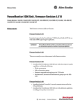
ControlLogix Time Synchronization Module
High accuracy position application
Catalog Number 1756HP-TIME Series B
Important User Information
Read this document and the documents listed in the additional resources section about installation, configuration, and
operation of this equipment before you install, configure, operate, or maintain this product. Users are required to
familiarize themselves with installation and wiring instructions in addition to requirements of all applicable codes, laws,
and standards.
Activities including installation, adjustments, putting into service, use, assembly, disassembly, and maintenance are required
to be carried out by suitably trained personnel in accordance with applicable code of practice.
If this equipment is used in a manner not specified by the manufacturer, the protection provided by the equipment may be
impaired.
In no event will Rockwell Automation, Inc. be responsible or liable for indirect or consequential damages resulting from the
use or application of this equipment.
The examples and diagrams in this manual are included solely for illustrative purposes. Because of the many variables and
requirements associated with any particular installation, Rockwell Automation, Inc. cannot assume responsibility or
liability for actual use based on the examples and diagrams.
No patent liability is assumed by Rockwell Automation, Inc. with respect to use of information, circuits, equipment, or
software described in this manual.
Reproduction of the contents of this manual, in whole or in part, without written permission of Rockwell Automation,
Inc., is prohibited.
Throughout this manual, when necessary, we use notes to make you aware of safety considerations.
WARNING: Identifies information about practices or circumstances that can cause an explosion in a hazardous environment,
which may lead to personal injury or death, property damage, or economic loss.
ATTENTION: Identifies information about practices or circumstances that can lead to personal injury or death, property
damage, or economic loss. Attentions help you identify a hazard, avoid a hazard, and recognize the consequence.
IMPORTANT: Identifies information that is critical for successful application and understanding of the product.
Labels may also be on or inside the equipment to provide specific precautions.
SHOCK HAZARD: Labels may be on or inside the equipment, for example, a drive or motor, to alert people that dangerous
voltage may be present.
BURN HAZARD: Labels may be on or inside the equipment, for example, a drive or motor, to alert people that surfaces may reach
dangerous temperatures.
ARC FLASH HAZARD: Labels may be on or inside the equipment, for example, a motor control center, to alert people to
potential Arc Flash. Arc Flash will cause severe injury or death. Wear proper Personal Protective Equipment (PPE). Follow ALL
Regulatory requirements for safe work practices and for Personal Protective Equipment (PPE).
Allen-Bradley, Rockwell Software, Rockwell Automation, ControlLogix, Logix5000, Studio 5000, and RSLogix are trademarks of Rockwell Automation, Inc.
Trademarks not belonging to Rockwell Automation are property of their respective companies.
Contents
Contents
High accuracy position application ............................................................................................................................................................. 1
ControlLogix Time Synchronization Module .......................................................................................................................................... 1
Studio 5000 Environment ........................................................................................................................................................................ 2
1756HP-TIME Overview ........................................................................................................................................................................ 2
Additional Resources ................................................................................................................................................................................. 2
Introduction ..................................................................................................................................................................................................... 3
Hardware ...................................................................................................................................................................................................... 4
Software ........................................................................................................................................................................................................ 4
Setup................................................................................................................................................................................................................... 5
Initial Setup ................................................................................................................................................................................................. 5
Basic Operation........................................................................................................................................................................................... 5
Software ........................................................................................................................................................................................................ 5
Configuration................................................................................................................................................................................................... 6
1756HP-TIME ........................................................................................................................................................................................... 6
Trimble BX982 ........................................................................................................................................................................................... 8
Operation ........................................................................................................................................................................................................ 10
Logix5000 Controller Input Image ...................................................................................................................................................... 10
Logix5000 Controller Output Image ................................................................................................................................................... 13
Example Code ........................................................................................................................................................................................... 13
CIP Message.......................................................................................................................................................................................... 13
ExtGPS UDT ....................................................................................................................................................................................... 14
GPSTransform AOI ........................................................................................................................................................................... 14
Appendix A – Trimble BX982 Setup ....................................................................................................................................................... 15
Appendix B – Base station with Rover Setup .......................................................................................................................................... 19
Specifications .................................................................................................................................................................................................. 21
Technical Specifications .......................................................................................................................................................................... 21
Dimensions ................................................................................................................................................................................................ 22
1756HP-TIME Module Status .................................................................................................................................................................. 23
Status Indicators ....................................................................................................................................................................................... 23
Glossary ........................................................................................................................................................................................................... 24
Preface
Studio 5000 Environment
The Studio 5000™ Engineering and Design Environment combines engineering
and design elements into a common environment. The first element in the
Studio 5000 environment is the Logix Designer application. The Logix Designer
application is the rebranding of RSLogix™ 5000 software.
The Studio 5000 environment is the foundation for the future of Rockwell
Automation® engineering design tools and capabilities. This environment is the
one place for design engineers to develop all the elements of their control system.
1756HP-TIME Overview
This document describes the additional functionality, of the 1756HP-TIME
module Series B, firmware revision 3.002, which allows for the use of an external
Trimble GPS unit to provide a more accurate positioning application.
Additional Resources
These documents contain additional information concerning related products
from Rockwell Automation.
Resource
Description
Integrated Architecture and CIP Sync Configuration
Application Technique, publication IA-AT003
This document explains CIP Sync technology and how
you can synchronize clocks within the Rockwell
Automation® Integrated Architecture.
Describes the necessary tasks to install, configure,
program, and operate a ControlLogix system.
Provides general guidelines for installing a Rockwell
Automation industrial system.
ControlLogix System User Manual, publication 1756-UM001
Industrial Automation Wiring and Grounding Guidelines,
publication 1770-IN414
Product Certifications website, http://www.ab.com
ControlFLASH® Firmware Upgrade Software 1756-um105
1756HP-TIME User Manual 1756-UM542
Provides declarations of conformity, certificates, and
other certification details.
Describes the necessary tasks to install, and use
ControlFlash to update the module firmware.
Describes the necessary tasks to install, configure,
program, and operate a 1756HP-TIME module.
You can view or download publications at
http:/www.rockwellautomation.com/literature/
2
Introduction
Introduction
This document serves as an additional document to describe a specific feature of
the 1756HP-TIME module, namely the high accuracy application. This
application will be illustrated using a Trimble BX982 unit.
3
Introduction
Hardware
The basic system comprises the following hardwware componetns:
• 1756HP-TIME module
• Trimble BX982 GNSS receiver enclosures
• Trimble Zephyr Antennas
• ControlLogix Equipment, Chassis, Controller and Ethernet Card
Figure 1: Setup
The picture above describes the most basic setup using one BX982 unit, there are
other alternatives which include using 2 BX982 units (for example: one as a base,
and one as a rover, using differential calculations) to obtain higher accuracy.
Contact your local Trimble representative for more options and configurations.
Software
The following software is needed to configure and use the 1756HP-TIME
module:
• The Studio 5000 Logix Designer application ladder example code.
• The Add-on Profile (AOP) for the 1756HP-TIME module both
of which are available for download at:
http://www.hiprom.com/Pages/Products/1756_CLX/1756HPTIME/web/1756HP-TIME.htm
• Web browser.
4
Setup
Setup
Initial Setup
Please consult the 1756HP-TIME user manual for additional instructions on
how to configure the IP address of the module, use ControlFlash to upgrade to
the latest firmware, and install/configure the Add-On-Profile (AOP).
Basic Operation
The system makes use of the Trimble BX982 unit to obtain high accuracy
position measurements.
There are 4 levels of position accuracy (1 sigma) you can reach with the Trimble
units, depending on the method/setup used:
Autonomous only:
Autonomous with SBAS:
DGPS / DGNSS:
Full RTK:
~1.5m hor. / 3m vert.
0.5m hor. / 0.85m vert. (e.g. with
EGNOS)
0.25m hor. / 0.5m vert. + 1ppm
(L1-only)
0.8cm hor. / 1,5cm vert. + 1ppm
(L1/L2 or L1-only versions)
The positioning data is then passed to the 1756HP-TIME module over
Ethernet, using the GSOF protocol, and the relevant data is available in Studio
5000, in the Time Module Input tags as well as a specifically created UDT. See
the Operation Section for more information on this data.
Software
The BX982 unit can be configured using any internet browser. The 1756HPTIME is configured using Studio 5000 Logix Designer software. An example
project is available for download (available here) which contains logic capable of
transforming the ECEF (Earth-Centered-Earth-Fixed) coordinates to a local
metric based coordinate system, as well as a message instruction to get additional
data from the Trimble unit.
5
Configuration
Configuration
1756HP-TIME
The 1756HP-TIME module and Trimble unit communicate using the GSOF
protocol over Ethernet. Therefore the TIME module and Trimble unit must be
connected to the same physical EtherNet network, either on the same subnet or
with a suitable gateway configuration.
In this document the IP configuration parameters are as follows:
Trimble BX982
1756HP-TIME module
192.168.1.98
192.168.1.151
Before you can configure the 1756HP-TIME module, the AOP for the module
must be installed. The installer for the AOP can be found at
http://www.hiprom.com/Pages/Products/1756_CLX/1756HPTIME/web/1756HP-TIME.htm
IMPORTANT
Each 1756HP-TIME module is programmed to work with a single
Logix5000 Controller.
Follow these steps to configure the 1756HP-TIME module in the Logix
Designer application.
1. Double-click the 1756HP-TIME module in the I/O tree in the
Logix Designer Application.
The New Module dialog box appears.
2. Enter a Name for the module.
6
Configuration
3. Click the Configuration tab.
4. From the Source Setting pull-down menu, choose the External GPS
(Receiver) option.
5. Click the Apply button.
6. Enter the IP address of the Trimble BX982 in the External Source
Address
7
Configuration
The properties of the 1756HP-TIME module are now configured.
Trimble BX982
There are many varieties of Trimble BX982 units to choose from, contact your
local Trimble representative to order the unit that best suits your application.
Basic setup of the unit should include the following:
1. Install the unit in a suitable position such that the antenna has an
unimpeded view of the sky.
2. Connect to the unit using the configured IP address. To accomplish
this, please follow the manufacturer’s instructions.
3. Log in to the webserver using the default security parameters:
• Username : admin
• Password : password
4. Navigate to Receiver Configuration | Antenna,
Antenna and select the
correct antenna configuration.
5. The unit should now start tracking satellites and resolving its
position.
6. Navigate to I/O Configuration | Port Configuration and add a
new TCP/IP port, as follows :
• Type : GSOF
• Port : 5017
• Client : Off
• Output Only : On
• UDP Mode : Off
7. Select the following Input/Output GSOF messages, with a 1Hz
frequency.
• Current Time UTC
• Lat, Long, Ht
• Position Sigma
• Position Time
• Velocity
• ECEF Position
8
Configuration
Please see Appendix A for screenshots of how to set up the BX982 unit to
communicate with the 1756HP- TIME module.
Once the TIME module and BX982 units are successfully configured and
communication the ‘SYNC’ LED on the TIME module should turn green.
If you are using two Trimble units for differential corrections, one will need to be
configured as a fixed base station, and one as a moving rover. The base station
will send the CMR/RTCM Differential Corrections to the rover for relative
positioning. See Appendix B for a description on how to configure a base
station/rover application.
IMPORTANT
9
The LED colors are different to what is observed in normal operation when
the module is in External GPS mode. The SYNC LED, when green, indicates a
connection to the Trimble unit. The PPS LED is tied to the onboard GPS unit,
and illustrates the accuracy of the time when in External GPS mode. If
accurate time is needed along with the positioning, the internal GPS unit
must have an antenna connected. Once the GPS receives lock it will
synchronize the PPS and the time will be accurate to GPS time (within ±50
ns). A flashing red PPS LED is not indicative of any error in communication
with the external Trimble unit. See 1756HP-TIME Module Status Indicators
section for more information.
Operation
Operation
Logix5000 Controller Input
Image
There are certain Input image tags which are specific for the External GPS mode
of operation. These are outlined in more detail below.
Table 1 – Logix5000 Controller Input Image Parameters Specific to External GPS
Parameter
Description
Value
1 = GPS
2 = IRIG-B
3 = PTP
4 = NTP
5 = External GPS
6 = Simulation
Source
Indicates the current time source.
Time.TimeValid
Indicates if a valid time is being received from the time source.
0 = Time being received from source is invalid
1 = Time being received from source is valid
Displays the current year received from the time source.
Example:
27/04/2010
13:45:22 - 234567 μs
Year = 2010
Displays the current month received from the time source.
Example:
27/04/2010
13:45:22 - 234567 μs
Month = 4
Displays the current day received from the time source.
Example:
27/04/2010
13:45:22 - 234567 μs
Day = 27
Displays the current hour received from the time source.
Example:
27/04/2010
13:45:22 - 234567 μs
Hour = 13
Displays the current minute received from the time source.
Example:
27/04/2010
13:45:22 - 234567 μs
Minute = 45
Displays the current second received from the time source.
Example:
27/04/2010
13:45:22 - 234567 μs
Second = 22
Time.Microsecond
Displays the current microsecond received from the time source.
Example:
27/04/2010
13:45:22 - 234567 μs
Microsecond = 234567
Note: The time is only valid if the Time.TimeValid bit is set.
Time.UTC
This is the current UTC in microseconds since the time base. The time
origin is based on all versions of the Studio 5000 Logix Designer.
Please refer to the example code for how this is used to time-stamp
events in sequence-of-events (SOE) modules in RSLogix versions
earlier than 18.
Example:
02 April 2014
14:12:41
UTC = 87277992127872
GPS.GPSLock
Indicates if the GPS receiver has lock.
0 = GPS receiver does not have lock
1 = GPS receiver has locked onto sufficient satellites
GPS.AntennaOK
Indicates if the antenna is connected and is operational.
0 = The antenna is either not present or is faulty
1 = The antenna is connected correctly and is operational
Time.Year
Time.Month
Time.Day
Time.Hour
Time.Minute
Time.Second
10
Operation
GPS.HDOPOk
Horizontal Dilution of Precision (HDOP) occurs when there are sufficient
satellites in lock, but two or more satellites occupy similar positions in
the sky (therefore decreasing the number of effective satellites).
0 = HDOP is currently active
1 = HDOP is not active
GPS.PPS
The pulse per second toggles at the exact moment the second changes
and the microseconds are zero.
Note: because the actual RPI is 50 ms, the accuracy is lost in the input
image.
0 = It has been more than 100 ms since the roll-over pulse of the last
second
1 = It has been less than 100 ms since the roll-over pulse of the last
second
GPS.FaultCode
Reserved.
–
GPS.Mode
These bits can be used to determine the quality of the position, to ensure –
that the data being received is of the required accuracy. See table 2 below
for details.
GPS.SVCount
Indicates the number of satellites that the GPS receiver is locked on.
GPS.Latitude
Displays the current position Latitude in degrees.
GPS.Longitude
Displays the current position Longitude in degrees.
GPS.Altitude
GPS.RelativePositionX
This is a number between 0…12
Example:
S26°05'17.0
"
E28°00'21.3
" Elev:
Example:
S26°05'17.0
"
E28°00'21.3
" Elev:
1577m
Example:
S26°05'17.0"
E28°00'21.3"
Elev: 1577m
Elevation =
See Example code for use and implementation
The relative position variables help to give an increased accuracy position 1577
parameter; as the calculations are performed in the Time module using
floating point math, to remove any rounding errors. The values indicates
the relative position from the reference station that the antenna is (in
meters). The formula to calculate is as follows: GPS.RelativePositionX =
PositionX (from Ext GPS) – ReferencePositionX (from Output Image).
Displays the current position Altitude in meters.
GPS.RelativePositionY
GPS.RelativePositionY = PositionY (from Ext GPS) – ReferencePositionY
(from Output Image).
See Example code for use and implementation
GPS.RelativePositionZ
GPS.RelativePositionZ = PositionZ (from Ext GPS) – ReferencePositionZ
(from Output Image).
See Example code for use and implementation
Table 2: GPS Mode Interpretation
Bit
Description
Interpretation
0
New position
0: No. 1: Yes.
1
Clock fix calculated for current position
0: No. 1: Yes.
2
Horizontal coordinates calculated this position
0: No. 1: Yes.
3
Height calculated this position
0: No. 1: Yes.
4
Weighted position
0: No. 1: Yes.
5
Overdetermined position
0: No. 1: Yes.
11
Operation
6
Ionosphere-free position
0: No. 1: Yes.
7
Position uses filtered L1 pseudo ranges
0: No. 1: Yes.
8
Differential position
0: Differential position is an autonomous or a WAAS solution. 1:
Position is a differential solution.
9
Differential position method
10
Differential position method'
0: Code 1: Phase including RTK, HP or XP OmniSTAR (VBS is not derived
from Phase).
0: Code (DGPS) or a float position (RTK). Uncorrected position is
Autonomous (if bit 0 = 0). 1: Position is fixed integer phase position
(RTK). Uncorrected position is WAAS (if bit 0 = 0).
11
OmniSTAR solution
0: Not active 1: OmniSTAR differential solution (including HP, XP, and
VBS)
12
Position determined with static as a constraint
0: No. 1: Yes.
13
Position is network RTK solution
0: No. 1: Yes.
14
Position is Location RTK
0: No. 1: Yes.
15
Position is Beacon DGPS
0: No. 1: Yes.
12
Operation
Logix5000 Controller Output
Image
This section provides descriptions for the Logix5000 controller output image
parameters.
Table 3 – Logix5000 Controller Output Image Parameters
Parameter
Description
Value
ReferencePositionX
The reference position variables help to give increased accuracy to the RelativePosition See Example code for use and implementation
input image tags; as the calculations are performed in the Time module using floating
point math, to remove any rounding errors. The formula to calculate is as follows:
GPS.RelativePositionX = PositionX (from Ext GPS) – ReferencePositionX (from Output
Image).
ReferencePositionY
GPS.RelativePositionY = PositionY (from Ext GPS) – ReferencePositionY (from Output
Image).
See Example code for use and implementation
ReferencePositionZ
GPS.RelativePositionZ = PositionZ (from Ext GPS) – ReferencePositionZ (from Output
Image).
See Example code for use and implementation
Example Code
The example code found at
http://www.hiprom.com/Pages/Products/1756_CLX/1756HPTIME/web/1756HP-TIME.htm has the following components:
• CIP message to read additional External GPS data from the 1756HPTIME module.
• UDT (ExtGPS) which allows the data received in the message to be
displayed in a manageable format.
• Add-On-Defined code to transform the ECEF Cartesian coordinates
referenced to a Base Origin to local North, East and Upward.
A brief explanation of each follows.
CIP Message
The parameters for the CIP message required to read the External GPS data from
the 1756HP-TIME module is displayed in the screenshot below:
13
Operation
ExtGPS UDT
The UDT (User Defined Type) is used to store the result of the CIP message
defined above. The structure is as follows.
GPSTransform AOI
The GPSTransform takes a base X, Y and Z position (use the Output Image
Tags for this purpose) and the current relative positions (calculated in the
1756HP-TIME module, and found in the Input Image) to give Local North,
East and Upward values.
14
Appendix A – Trimble BX982 Setup
Appendix A --- Trimble BX982 Setup
Open a web browser, and point the address to the configured IP address of the BX982. The default username and password
are ‘admin’ and ‘Password’ respectively.
The following page should then be available.
The navigation pane on the left hand side can be used to view various status, activity and configuration parameters of the
BX982.
15
Appendix A – Trimble BX982 Setup
16
Appendix A – Trimble BX982 Setup
17
Appendix A – Trimble BX982 Setup
18
Appendix B – Base station with Rover
Appendix B --- Base station with Rover Setup
Base station setup:
1. Install the unit in a suitable position such that the antenna has an unimpeded view of the sky.
2. Connect to the unit using the configured IP address. To accomplish this, please follow the manufacturer’s
instructions.
3. Log in to the webserver using the default security parameters:
• Username : admin
• Password : password
4. Navigate to Receiver Configuration | Antenna,
Antenna and select the correct antenna configuration.
5. The unit should now start tracking satellites and resolving its position.
6. Navigate to Receiver Configuration | Reference Station and select the “Load Current Position” by pressing the
“Here
Here”
Here button.
7. Navigate to I/O Configuration | Port Configuration and add a new TCP/IP port, as follows :
• Type : CMR
• Port : 5018
• Client : Off
• Output Only : On
• UDP Mode : Off
• Delay : 0 ms
19
Appendix B – Base station with Rover
Rover setup:
1. Install the unit in a suitable position such that the antenna has an unimpeded view of the sky.
2. Connect to the unit using the configured IP address. To accomplish this, please follow the manufacturer’s
instructions.
3. Log in to the webserver using the default security parameters:
• Username : admin
• Password : password
4. Navigate to Receiver Configuration | Antenna,
Antenna and select the correct antenna configuration.
5. The unit should now start tracking satellites and resolving its position.
6. Navigate to I/O Configuration | Port Configuration and add a new TCP/IP port, as follows :
• Type : GSOF
• Port : 5017
• Client : Off
• Output Only : On
• UDP Mode : Off
• Remote IP : (IP address of Base Station) : 5018
• CMR Input : Disabled
7. Select the following Input/Output GSOF messages, with a 1Hz frequency.
• Current Time UTC
• Lat, Long, Ht
• Position Sigma
• Position Time
• Velocity
• ECEF Position
20
Specifications
Specifications
Technical Specifications
The following table lists the technical specifications for the 1756HP-TIME
module. Additional information will be made available once the values have been
ascertained.
Attribute
Value
Power requirements
All power is derived from the 1756 backplane.
Current draw @ 5 V – 736 mA
Current draw @ 24 V – 1.64 mA
Power consumption
Operating temperature
0…50 °C (32…122 °F)
Storage temperature
21
Relative humidity
5… 95% noncondensing
Operating shock
TBA
Storage shock
TBA
Vibration
TBA
Emissions
TBA
ESD immunity
TBA
Radiated RF immunity
TBA
EFT/B immunity
TBA
Conducted RF immunity
TBA
Enclosure type rating
IP20
Ethernet conductor
CAT5 STP
Specifications
Dimensions
The following drawing shows the dimensions of the 1756HP-TIME module.
22
1756HP-TIME Module Status
1756HP-TIME Module Status
The display on the front of the 1756HP-TIME module provides status
indicators and messages.
Status Indicators
The 1756HP-TIME module provides three status indicators on the display.
These LEDs indicate slightly different information when in External GPS mode
than in any other Input mode.
Status
Indicator
PPS
23
Description
This indicator is toggled every second for 100 ms at the exact PPS (Pulse Per Second).
Green = the internal GPS is locked and receiving a valid PPS from the satellites.
Red = the internal GPS is not locked, or the antenna is missing.
LOC
Green = the module is communicating properly with the External Trimble unit.
Red = the module is not communicating properly with the External Trimble unit.
OK
Green = the module has started successfully.
Red = the module has a hardware fault.
Glossary
Glossary
The following terms and abbreviations are used throughout this manual. For
definitions of terms not listed here, refer to the Allen-Bradley Industrial
Automation Glossary, publication AG-7.1
Add-On Instructions
Best Master Clock Algorithm
Add-on instructions are custom Studio 5000 Logix Designer application
instructions that you design and create. With add-on instructions, you can create
new instructions for sets of commonly-used logic, provide a common interface to
this logic, and provide documentation for the instruction.
The algorithm performed by each node to determine the clock that will become
the master clock on a subnet and the grandmaster clock for the domain. The
algorithm primarily compares priority1, clock quality, priority2, and source
identity to determine the best master among available candidates.
Boundary Clock A boundary clock has more than one port, for example, a managed Ethernet
switch, and perform the duties as a master or slave clock.
Common Industrial Protocol (CIP)
The Common Industrial Protocol (CIP) is an open industrial protocol for
industrial automation applications.
CIP Sync CIP Sync is the Open DeviceNet Vendors Association (ODVA) implementation
of the Institute of Electrical and Electronics Engineers (IEEE) 1588-2008
standard. The protocol provides a mechanism to synchronize clocks between
controllers, I/O devices, and other automation products.
Clock A node participating in the PTP protocol that is capable of providing a
measurement of the passage of time since a defined epoch. There are three types
of clocks in IEEE 1588-2008: boundary, transparent, and ordinary clocks.
Coordinated System Time (CST)
In its simplest form, CST is a backplane clock propagated between all modules
on the ControlLogix backplane. Its presence is necessary whenever time
coordination between modules in the chassis is required.
Device Level Ring (DLR) A DLR network is a single-fault tolerant ring network intended for the
interconnection of automation devices. This topolog y is also implemented at the
device level. No additional switches are required.
Domain A logical grouping of clocks that synchronize to each other by using the PTP
protocol, but that are not necessarily synchronized to clocks in another domain.
Greenwhich Mean Time (GMT) GMT is the mean solar time of the longitude (0°) of the former Royal
Observatory at Greenwich, England, or Greenwich meridian. UTC replaced
GMT as the basis for the main reference time scale or civil time in various regions
on 1 January 1970.
Global Positioning System (GPS) GPS is a satellite-based navigation system made up of a network of 24 satellites
placed into orbit by the U.S. Department of Defense. GPS provides reliable timing
services (as well as positioning and navigation) on a continuous basis in all weather,
day and night, anywhere on or near the Earth that has an unobstructed view of
four or more GPS satellites.
Grandmaster (GM) Within a domain, a clock that is the ultimate source of time for clock
synchronization by using the CIP Sync protocol.
24
Glossary
Local Clock The clock on a device.
Master Clock (M) In the context of a single CIP Sync communication path, a clock that is the source
of time to which all other clocks on that path synchronize on a local subnet.
Network Time Protocol (NTP) A protocol for synchronizing the clocks of computer systems over packetswitched, variable-latency data networks.
Priorities (P1 and P2) Parameters that can override the best master clock algorithm to choose a different
grandmaster.
Precision Time Protocol (PTP)
The PTP protocol is a time-transfer protocol defined in the CIP Sync IEEE
1588-2008 standard that allows precise synchronization of networks.
Slave Clock A clock that synchronizes its local clock to a master time.
Sequence of Events (SOE) Sequence of events are any events that needs to be compared against a second
event.
Synchronized Clocks Two clocks are synchronized to a specified uncertainty if they have the same
epoch and their measurements of the time of a single event at an arbitrary time
differ by no more than that uncertainty.
System Time The absolute time value as defined by CIP Sync in the context of a distributed
time system where all devices have a local clock that is synchronized with a
common master clock. System time is a 64-bit integer value in units of
nanoseconds or microseconds with a value of 0 corresponding to an epoch of
January 1, 1970.
Time Sync Object The time sync object provides a Common Industrial Protocol (CIP) interface to
the IEEE 1588 (IEC 61588) standard for a precision clock synchronization
protocol for networked measurement and control systems. This information can
be collected to be used in diagnostics.
Transparent Clocks A device that measures the time taken for a PTP event message to transit the
device and provides this information to clocks receiving this PTP event message.
Coordinated Universal Time (UTC)
Wall Clock Time (WCT)
25
The time standard for 'civil time', representing time at the Prime Meridian
(0 degrees longitude). The time does not include time zone or daylight savings
time offsets. System time is the same as UTC.
Wall clock time is the controller’s time based on UTC system time.
Glossary
Rockw
Rockwe ll Automa
Automation S u p por
por t
Rockwell Automation provides technical information on the Web to assist you in using its products at:
http ://www.rockwellautomation.com/support
You can also visit our Support Center at https://rockwellautomation.custhelp.com/ for updates, support chats and forums,
technical information, FAQs, and to sign up for product notification updates.
In addition, we offer multiple support programs for installation, configuration, and troubleshooting. For more
information, contact your local distributor or Rockwell Automation representative, or visit
http://www.rockwellautomation.com/ser vices/online-phone
Installa
stallation Assistance
If you experience a problem within the first 24 hours of installation, review the information that is contained in this
manual. You can contact Customer Support for initial help in getting your product up and running.
United States or Canada
1.440.646.3434
Outside United States or Canada
Use the Worldwide Locator
http://www.rockwellautomation.com/rockwellautomation/support/overview.pa
Rockwell Automation representative.
New Produc
Produ c t S atisfac
tisfac tion Return
Rockwell Automation tests all of its products to help ensure that they are fully operational when shipped from the
manufacturing facility. However, if your product is not functioning and needs to be returned, follow these procedures.
United States
Contact your distributor. You must provide a Customer Support case number (call the phone number above to obtain one) to
your distributor to complete the return process.
Outside United States
Please contact your local Rockwell Automation representative for the return procedure.
Doc
Doc umenta
umentation Fe edback
Your comments will help us serve your documentation needs better. If you have any suggestions on how to improve this
document, complete this form, publication RA-DU002 http://www.rockwellautomation.com/literature/.
Rockwell Otomasyon Ticaret A.Ş., Kar Plaza İş Merkezi E Blok Kat:6 34752 İçerenköy, İstanbul, Tel: +90 (216) 5698400
26