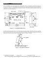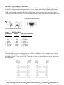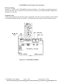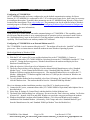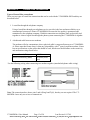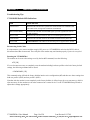
1
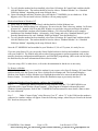
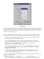
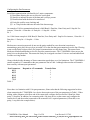
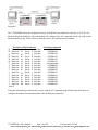
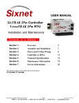
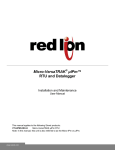
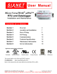
USER MANUAL VT-MODEM-4 Leased Line Industrial Modem Installation & Maintenance Contents at a Glance: Section 1 Overview 2 Section 2 Performance Specifications 3 Section 3 VT-MODEM Mounting 4 Section 4 Electrical Connections 5 Section 5 Modem Configuration 7 Section 6 Leased Line Connections 10 Section 7 Maintenance Information 11 Section 8 Product Support & Other Documents 12 This manual applies to the following product: Leased line modem (VT-MODEM-4##) VT-MODEM-4 User Manual Page 1 of 20 Last Revised: 8/17/09 Sixnet Technology Park 331 Ushers Road Clifton Park, NY 12065 USA +1 (518) 877-5173 [email protected] Section 1 Overview The VT-MODEM-4 is a rugged industrial telephone modem that has been designed for operation in electrical enclosures installed in harsh environments. The VT-MODEM-4 supports all standard Hayes AT commands, Fax Class 1 and Class 2 commands and S-registers and therefore can be set-up as an external modem on any PC. The VT-MODEM-4 is compatible with most telecommunications or dial-up networking software. A VT-MODEM-4 allows easy access to PLCs, Sixnet I/O and other devices via dial-in telephone connections or leased line connections. The modem may be DIN rail or panel mounted for convenient and easy installation adjacent to other DIN rail components inside of new or existing enclosures. Most Windows software can communicate through a VT-MODEM-4 to remote devices to perform file transfers, diagnostics, program debugging and many other operations. Use the VT-MODEM-4 in dial-up and leased line applications. The Industrial Sixnet VT-MODEM-4 allows for remote access to 3rd Party devices. VT-MODEM-4 User Manual Page 2 of 20 Last Revised: 8/17/09 Sixnet Technology Park 331 Ushers Road Clifton Park, NY 12065 USA +1 (518) 877-5173 [email protected] Section 2 Performance Specifications Telephone Line Max. Data Rate Compatibility Data Compression Error Correction Max Fax Modem Rate Fax Modem Compatibility Ringer Equivalent Line Jack Phone Jack Transmit Level Receiver Sensitivity RS232 Port Max. RS232 Rate RS232 Signal Support RS232 Connector Command Set CD Status LEDs (Carrier detect) 33600 bps (V.34) V.34 enhanced, V.34, V.32bis, V.32, V.22bis, V.22A/B, V.23, V.21, Bell212A & 103 V.42 bis (4:1) and MNP 5 (2:1) V.42/MNP 3-4 33.6 kbps ITU-T “Super” Group 3; Class 1.0, 2.0, 2.1; Group 3, Class 1 and 2, T.4, T.30, V.21, V.27ter, V.29, V.34, V.17, and TIA/EIA TR29.2 0.3 RJ11 RJ11 –11 dBm –43 dBm under worst-case conditions 115.2 kbps (Kilobaud) TXD, RXD, CTS, RTS, DCD, DTR, DSR, RI, GND (None - Flow Control Not Supported) DB9 female, RS232 All standard AT and S register commands including Class 1 and Class 2 Fax commands The modem has detected a carrier on the phone line (a remote modem has been detected). The PC (or Sixnet Station) has established a connection to the modem and is ready. Flashes as data is received from the phone line. Flashes as data is sent out the phone line. On when power is present. TR (Data Terminal Ready) RD (Receive Data) TD (Transmit Data) Power General Characteristics Input Power 10 - 30 VDC Input Current 75mA @ 24VDC (typical) 52mA @ 24VDC (Sleep Inactivity Mode) Certification FCC Part 15 and FCC Part 68; UL 508; CSA C22.2/14; ACA TS 001- 1997; ACA TS 002-1997; AS/NZS3260-1993; AS/NZS3548-1995; CTR21 (98/482/EC); EN55022; IEC 950:1991. Operating Temperature -30 ° to 70 ° C Storage Temperature -40 ° to 85 ° C Humidity 5 to 95% RH (non-condensing) Mounting DIN rail or panel mount Dimensions W x 4.75L x 1.35H inches (8.2 W x 12.1 L x 3.4H cm) VT-MODEM-4 User Manual Page 3 of 20 Last Revised: 8/17/09 Sixnet Technology Park 331 Ushers Road Clifton Park, NY 12065 USA +1 (518) 877-5173 [email protected] Section 3 VT-MODEM Mounting The VT-MODEM-4 snaps onto standard DIN rail (DIN EN 50022) or is mounted to a flat panel using #6 or #8 screws. See Figure 3-1. The modem can be installed in any orientation, directly adjacent to other DIN rail components or in any convenient location within the enclosure. The modem should be installed within 6 feet of the device it will be connected to. Figure 3-1: VT-MODEM DIMENSIONS For DIN rail mounting, hook the top, rear of the modem onto the top edge of the DIN rail. Using a small flat head screwdriver, pull down on the spring-loaded tab on the bottom of the modem and push the modem back against the rail. Reverse these steps to remove the modem. See Figure 3-2 below. Figure 3-2: DIN RAIL MOUNTING VT-MODEM-4 User Manual Page 4 of 20 Last Revised: 8/17/09 Sixnet Technology Park 331 Ushers Road Clifton Park, NY 12065 USA +1 (518) 877-5173 [email protected] Section 4 Electrical Connections RS232 Connections: Use the Sixnet RS232 cable (VT-CABLE-MDM, which is 6 feet in length) or an equivalent cable to connect the modem's RS232 port (DB9 Male cable end) to the RS232 port on a SIXTRAK Gateway, VersaTRAK RTU or PC (DB9 Female cable end). As shown in Figure 4-1, the VT-CABLE-MDM is a straight through serial communications cable suitable for connecting a DTE device (PC, Gateway or VersaTRAK) to a DCE device (VT-MODEM). For IPm and ST-GT-1210 stations, use a straight-through Ethernet cable (not supplied) and the RJ45 to DB9 male adapter that comes with the station. Cable requirements for PLCs and other devices may be different. Refer to the PLC or other device’s documentation for cable pin-outs. Some PLC cables are documented in the Technical notes provided on the Sixnet CD that came with your modem. Figure 4-1: VT-CABLE-MDM Wiring VT-MODEM-4 User Manual Page 5 of 20 Last Revised: 8/17/09 Sixnet Technology Park 331 Ushers Road Clifton Park, NY 12065 USA +1 (518) 877-5173 [email protected] IPm and ST-GT-1210 RS232 Connections An un-wired DB9M to RJ45F adapter is provided for the RS232 port on the controller. The pin-outs follow the EIA/TIA-561standard (See the figure below). Use this adapter along with a RJ45 male to RJ45 male straight-thru wired patch cable (not included) to make a connection between the VT-MODEM-4’s COM port (DB9 Female) and the controllers RJ45 Female RS232 port. Enable hardware flow control in the IPm’s COM port configuration. Refer to the Sixnet Electronic catalog for more information on connecting to other equipment. Typical Modem Adapter Wiring: Sixnet RJ45F to DB9M RJ45F Pin #, Adapter wire color Signal Name 1 N/A Blue 2 N/A Orange 3 N/A Black 4 GND Red 5 RXD in Green 6 TXD out Yellow 7 CTS in Brown 8 RTS out White DB9 Male Connector Pin #, Signal Name 9 RI out 1 DCD out 4 DTR in 5 GND 2 RXD out 3 TXD in 8 CTS out 7 RTS in 3rd Party PLC/Device Connections: Determine if the device you are connecting to is a DTE or a DCE device. Use a straight-through cable to connect the VT-MODEM to a DTE 3rd party device. A cross-wired cable must be used to connect the VTMODEM to a DCE 3rd party device. If the 3rd party device does not support flow control pins 7 and 8 must be tied together. VT-MODEM-4 User Manual Page 6 of 20 Last Revised: 8/17/09 Sixnet Technology Park 331 Ushers Road Clifton Park, NY 12065 USA +1 (518) 877-5173 [email protected] VT-MODEM-4 Power, Phone Line Connections: DC Power Wiring Connect 10 - 30 VDC to the VT-MODEM-4 as shown in Figure 4-2. The modem can usually be powered from the same DC source as other devices in the enclosure. All the screw terminals should be tightened to a maximum of 3.48 in-lbs. Telephone Cable Connect analog phone lines to the RJ-11 jacks as appropriate. One RJ-11 jack is provided to connect directly to a telephone (optional) and the second RJ-11 jack functions as the connection to the telephone network. Figure 4-2: VT-MODEM-4 WIRING VT-MODEM-4 User Manual Page 7 of 20 Last Revised: 8/17/09 Sixnet Technology Park 331 Ushers Road Clifton Park, NY 12065 USA +1 (518) 877-5173 [email protected] Section 5 Modem Configuration Configuring a VT-MODEM-4: All VT-MODEM models are factory configured to use the default communication settings for Sixnet Stations. If a VT-MODEM-4 is connected to a PLC, PC or other non-Sixnet device, then it may be necessary to reconfigure the modem. To modify these parameters use the VT-MODEM Setup Wizard (v2.00 or later) located on the latest Sixnet CD or www.sixnet.com. The parameters can also be modified using a Windows terminal program or Windows HyperTerminal (See Configuring Windows HyperTerminal to configure the VT-MODEM-4 for more information). AT Command String at Power-up Upon power-up, a Sixnet station can send a command string to a VT-MODEM-4. This capability can be used to assure that the modem is set to a particular mode of operation, such as auto answer mode. Refer to the “Set Modem String” topic in the Sixnet I/O Tool Kit program’s online help for information on this capability. The Sixnet Station can send any standard AT command. Configuring a VT-MODEM-4 as an External Modem on a PC: The VT-MODEM-4 can be connected directly to a PC. The modem will need to be “installed” in Windows prior to use. Here are instructions to install the modem in most Windows Operating Systems. Modem Installation in Windows 95/98 Plug and Play method (recommended): 1) With the PC off, connect DC power and the telephone line to the VT-MODEM-4. Connect a communications cable (VT-CABLE-MDM or equivalent) between the VT-MODEM-4 and the PC. Turn on the PC. During the boot-up process, Windows should detect the modem and display the New Hardware Found dialog box. 2) Make the selection “Select from a list of alternative drivers”. 3) The Select Device dialog will be displayed. In the column labeled Manufacturers, select “Standard Modem Types”. In the column labeled Models, select “Standard 28800 bps Modem”. Click OK. Windows will then complete the boot-up process. (The standard Windows driver is used for the VTModem. Although the VT-Modem supports baud rates to 33,600 bps, the selections in Windows are limited to 28800 bps.) 4) To verify that the modem has been installed, select Start Settings Control Panel, and then double click the Modems icon. The modem should be listed as “Standard 28800 bps Modem”. Here is an alternate modem installation procedure (use if the PC is already powered up): 1) Connect the DC power, communications cable (VT-CABLE-MDM or equivalent) and telephone line as described above. 2) Select Start Settings Control Panel, and then double click the Modems icon. 3) The Install New Modem dialog box will appear. Do not select the “Don’t detect my modem, I will select it from a list”. Instead, click Next and allow Windows to search the com ports and detect the modem. 4) Windows should find a modem called Standard Modem. Click Next and Windows will complete installation of the Standard Modem. (Alternately, click Change and select “Standard Modem Types” from the Manufacturers list, and “Standard 28800 bps Modem” from the Models list.) VT-MODEM-4 User Manual Page 8 of 20 Last Revised: 8/17/09 Sixnet Technology Park 331 Ushers Road Clifton Park, NY 12065 USA +1 (518) 877-5173 [email protected] 5) To verify that the modem has been installed, select Start Settings Control Panel, and then double click the Modems icon. The modem should be listed as either a “Standard Modem” or a “Standard 28800 bps Modem” depending on the steps followed above. 6) Upon re-booting the machine, Windows may still find the VT-MODEM-4 as new hardware. If this happens, select “Do not install a driver (Windows will not prompt again)”. Modem Installation in Windows NT 1) Select Start Settings Control Panel, and then double click the Modems icon. 2) The Install New Modem dialog box will appear. Do not select the “Don’t detect my modem, I will select it from a list”. Instead, click Next and allow Windows to search the com ports and detect the modem. 3) Windows should find a modem called Standard Modem. Click Next and Windows will complete installation of the Standard Modem. (Alternately, click Change and select “Standard Modem Types” from the Manufacturers list, and “Standard 28800 bps Modem” from the Models list.) 4) To verify that the modem has been installed, select Start Settings Control Panel, and then double click the Modems icon. The modem should be listed as either a “Standard Modem” or a “Standard 28800 bps Modem” depending on the steps followed above. Once the VT-MODEM-4 has been added to your Windows 95, 98 or NT system, it is ready for use. If you are using Sixnet I/O, you can use the Sixnet Sixdial software to dial out and establish a connection with your Sixnet I/O. The Sixdial utility allows other Sixnet programs to perform operations such as data transfers, hardware configuration and diagnostics, and ISaGRAF programming. (Refer to the on-line help in the Sixdial utility for more information on these software tools). If you are using a PLC or other device, refer to the documentation for that device as necessary. To Remove a Modem If it ever becomes necessary to re-install the modem for any reason, select Start Settings Control Panel, and then double click the System icon. Next, click the Device Manager tab. The list should display a Modems icon. Double click the Modems icon. Highlight the modem to be removed and then click the Remove button. To reinstall the modem, follow the installation steps as previously described. Configuring Windows HyperTerminal to configure the VT-MODEM-4 Step 1: Connect your Industrial Modem to your computer using the VT-CABLE-MDM (or an equivalent cable). Open Windows HyperTerminal. (This program is included with most Microsoft Windows Operating Systems. Refer to the VT-MODEM-4 on-line manual for more details.) Enter a name for your connection. Step 2: Under “Connect Using” select Direct to Com “X”, where “X” is the COM port the modem is connected to. Another window will appear. Enter the following settings, where Bits per second is the desired PLC baud rate, then press OK: VT-MODEM-4 User Manual Page 9 of 20 Last Revised: 8/17/09 Sixnet Technology Park 331 Ushers Road Clifton Park, NY 12065 USA +1 (518) 877-5173 [email protected] Choose the baud rate that matches the PLC or other device that will be connected to the modem. Anytime a setting is saved using &W0 or &W1, the RS232 baud rate is memorized by the VT-Modem. The saved baud rate will be used for future communications with any attached device that does not initiate communications with the modem (such as most PLCs). Step 3: You should be at a blank screen. Test that you are connected by typing AT <enter>. The modem should respond with an OK if you are connected. Now enter these commands. (Press <enter> after each.) __ To check whether your Industrial Modem is communicating, look at the “TD” and “RD” LED's on the modem. They will light up when communicating. __ Use the AT commands listed in Section 6 to enter in the appropriate parameters. For example, to ignore DTR type AT&D0<enter> the modem should respond with an OK. To save the parameters to the modems NVRAM type AT&W0<enter> to store parameters in stored profile 0 and AT&W1<enter> to store parameters in Stored Profile 1. __ To dial a number in HyperTerminal, you can use the command: ATDT<number>. When you have successfully connected to another modem, it will show the baud rate at which you are connected. Example: ATDT15188778346 __ To Hang-up the connection Open the HyperTerminal session saved from the previous steps. Type +++, you should get an OK back, then type ATH <enter>. The resulting OK indicates that the modem-to-modem connection is terminated. __ If you are using a terminal program other than HyperTerminal, the steps may be different. However, the commands will remain the same. VT-MODEM-4 User Manual Page 10 of 20 Last Revised: 8/17/09 Sixnet Technology Park 331 Ushers Road Clifton Park, NY 12065 USA +1 (518) 877-5173 [email protected] Configuring the Port Parameters Serial data communication is defined by its 5 major components: (1) Baud Rate allowing the user to select the serial speed (2) Start bit to indicate the start of the data and is always present (3) Data bits that holds the data to be transferred (4) Parity bit used for error checking and (5) 1 or 2 Stop bits that indicates the end of the data message. An example of 10-bit communication format is 9600 Baud, 8 Data bits, None Parity and 1 Stop bit. For instance, 1 Start bit + 8 Data bits + 0 Parity bit + 1 Stop bit = 10 bits Ex.1 An 11-bit format example is 9600 Baud, 8 Data bits, Even Parity and 1 Stop bit. For instance, 1 Start bit + 8 Data bits + 1 Parity bit + 1 Stop bit = 11 bits Ex.2 Modem error correction protocols do not use the parity method for error detection/correction so transmitting a parity bit with every byte just adds 10% to the data that gets transmitted over the line. Electing to not use the Parity bit does allows for greater bit transmission over the phone lines. This means faster Modem-to-Modem and Modem-to-Service Provider connection rates. The VT-MODEM-4 does not use the parity bit over the phone line. This means the Parity bit is stripped out when 11-bits are used and added back in at the receiving modem. Along with the decide advantage of faster connection speeds there are a few limitations. The VT-MODEM-4 cannot respond to AT commands at the port parameters list in Table 1 although either modem will transfer data correctly with most port parameters. Port Parameters 8,E,1 8,E,2 8,O,1 8,O,2 7,N,1 Table 1 Respond to AT commands - Transfer Data - Since there is a limitation with 11-bit port parameters, Sixnet asks that the following suggestion be taken when connecting the VT-MODEM-4 to a device that requires one of the port parameters in Table 1. When dialing with a computer at the Host end of the connection, configure the host end for 8 Data bits, None parity, 1 Stop bits. In addition, for connecting with a 3rd party device on the remote end, configure the remote device and the modem connected to the remote device’s required parameters (8 Data bits, even parity, 1 stop bit in the example below). VT-MODEM-4 User Manual Page 11 of 20 Last Revised: 8/17/09 Sixnet Technology Park 331 Ushers Road Clifton Park, NY 12065 USA +1 (518) 877-5173 [email protected] Example 3 The VT-MODEM-4 must be configured correctly to handle the port parameters correctly as well. The Set Modem Wizard included free with your modem will configure these AT commands, but if you wish to enter them manually use the Table 2 below to send the correct AT commands to the modem. For these COM Parameters 8 Data bits N Parity 1 Stop bits 8 Data bits N Parity 2 Stop bits 8 Data bits E Parity 1 Stop bits 8 Data bits E Parity 2 Stop bits 8 Data bits O Parity 1 Stop bits 8 Data bits O Parity 2 Stop bits 7 Data bits N Parity 1 Stop bits 7 Data bits N Parity 2 Stop bits 7 Data bits E Parity 1 Stop bits 7 Data bits E Parity 2 Stop bits 7 Data bits O Parity 1 Stop bits 7 Data bits O Parity 2 Stop bits Parity 1 Stop bits 7 Data bits S Parity 2 Stop bits 7 Data bits S 7 Data bits M Parity 1 Stop bits 7 Data bits M Parity 2 Stop bits Table 2 Send these commands AT$EB0#P0 AT$EB0#P0 AT$EB1#P2 AT$EB1#P2 AT$EB1#P1 AT$EB1#P1 Not Supported AT$EB0#P0 AT$EB0#P2 AT$EB0#P2 AT$EB0#P1 AT$EB0#P1 AT$EB0#P0 AT$EB1#P0 AT$EB0#P0 AT$EB1#P0 Using the information provided in this section, send the AT command string defined in the table above to configure the modem for transferring data at the defined port parameters. VT-MODEM-4 User Manual Page 12 of 20 Last Revised: 8/17/09 Sixnet Technology Park 331 Ushers Road Clifton Park, NY 12065 USA +1 (518) 877-5173 [email protected] Section 6 Leased Line Connections Types of Leased Line connections: There are two types of leased line connections that can be used with the VT-MODEM-4WW and they are described below. 1. Leased line though the telephone company Using a leased line through your telephone service provider is the best and most reliable way to communicate between two Sixnet VT-MODEM-4s because the line quality is guaranteed and maintained by the telephone company. With this connection two telephone lines are basically tied together to create a logical line through the phone system connecting the VT-MODEM-4s together. 2. A dedicated cable between two modems The modems will also communicate when a physical cable is connected between two VT-MODEM4s. Please note that Sixnet doesn’t claim any compatibility with 3rd party leased line modems. Sixnet has no specifications on the cables that should be used, but the user should adhere to the sensitivity and attenuation ratings listed below. Transmit Level (dBm) Receiver Sensitivity (dBm) -11 dBm -43 dBm (worst case) Use the following wiring when connecting two modems together (standard telephone cable wiring). Note: The connection above shows pins 2 and 6 (Ring2 and Tip2), but they are not required. The VTMODEM-4 uses only two wires to communicate. VT-MODEM-4 User Manual Page 13 of 20 Last Revised: 8/17/09 Sixnet Technology Park 331 Ushers Road Clifton Park, NY 12065 USA +1 (518) 877-5173 [email protected] Section 7 Maintenance Information Troubleshooting Tips VT-MODEM Default LED Indications LED Default Indication Carrier Detect This LED will come ON once a phone line connection has been established, and will remain on for as long as the connection is maintained. Data Terminal Ready This LED will come ON when the DTR signal is present regardless the state of the &D command. Receive Data This LED will come ON whenever data is received through the phone line. Transmit Data This LED will come ON whenever the modem sends data out the phone line. Power LED Normal Indication: This LED will be ON when power is applied to the modem. Reconnecting Serial Cables It is important to cycle (remove and then reapply) DC power to a VT-MODEM-4 each time the RS232 cable is disconnected and then reconnected. The serial port of the modem may not function properly if power is not cycled. Resetting the VT-MODEM-4 The modem can be reset to the settings saved by the last &W command, issue the following: ATZ [CR] If it ever becomes necessary to completely reset the modem including both user profiles to the basic factory default settings, the following command can be issued: AT&F&W&W1 [CR] This command string will load the factory defaults into the active configuration (&F) and then save those settings into both user profile 0 (&W) and user profile 1 (&W1). Note that after the modem is reset completely to the factory defaults, it will no longer be set to auto-answer, which is often necessary for the modem to work when connected to a remote device. Use the VT-MODEM Setup Wizard to adjust these settings appropriately. VT-MODEM-4 User Manual Page 14 of 20 Last Revised: 8/17/09 Sixnet Technology Park 331 Ushers Road Clifton Park, NY 12065 USA +1 (518) 877-5173 [email protected] Section 8 Product Support and Additional Documents To obtain support for Sixnet products, call Sixnet and ask for applications engineering. Our phone numbers are: +1 (518) 877-5173 Office +1 (518) 877-8346 Fax E-mail: [email protected] Our mailing address: Sixnet Technology Park 331 Ushers Rd. Ballston Lake, NY 12019 Visit our web page at: http://www.sixnet.com BUYER PROTECTION PLAN Sixnet protects your investment in Sixnet industrial modems with this unique Buyer Protection Plan. Sixnet provides a liberal 18 month from time of purchase limited warranty (see below) on Sixnet industrial modems. We also offer an extended 36-month warranty option for users with long-term requirements. Sixnet promises to continue to maintain each model of industrial modem we offer for sale for a minimum of five years, so you can design your system only once and be assured of continued supply and high-quality after-sale service. We further promise to plan each product improvement and new feature to be upward compatible with existing designs and installations using the modem wizard to configure the modems. Our goal is to make each new product release better than the one it replaces by providing new features, increased reliability and performance, and continued support for existing features. Sixnet protects your investment even further with a liberal five-year trade-in policy. You may exchange standard Sixnet products for upgraded versions of the same or upward compatible products to take advantage of new features and performance improvements at any time for five years. A liberal prorated exchange allowance will be given for your existing equipment. You may contact Sixnet directly to trade-up on any industrial modem product. SIXNET INDUSTRIAL MODEM EXCHANGE ALLOWANCE Time Since the Original Purchase 0 to 1 Year 1 to 2 Years 2 to 3 Years 3 to 4 Years Over 4 Years Trade-In Allowance 50% 40% 30% 20% 10% VT-MODEM-4 User Manual Page 15 of 20 Last Revised: 8/17/09 Sixnet Technology Park 331 Ushers Road Clifton Park, NY 12065 USA +1 (518) 877-5173 [email protected] Sixnet Statement of Limited Warranty Sixnet LLC, manufacturer of Sixnet Industrial Modems, warrants to Buyer that products, except software, manufactured by Sixnet will be free from defects in material and workmanship. Sixnet's obligation under this warranty will be limited to repairing or replacing, at Sixnet's option, the defective parts within one year of the date of installation, or within 18 months of the date of shipment from the point of manufacture, whichever is sooner. Products may be returned by the buyer only after permission has been obtained from Sixnet. Buyer will prepay all freight charges to return any products to the repair facility designated by Sixnet. Sixnet further warrants that any software supplied as part of a product sale, except obsolete products, will be free from non-conformances with Sixnet published specifications for a period of 90 days from the time of delivery. While Sixnet endeavors to improve the features and performance of software associated with its products, no effort on the part of Sixnet to investigate, improve or modify Sixnet software at the request of a customer will obligate Sixnet in any way. This limited warranty does not cover losses or damages which occur in shipment to or from Buyer or due to improper installation, maintenance, misuse, neglect or any cause other than ordinary commercial or industrial applications. In particular, Sixnet makes no warranties whatsoever with respect to implied warranties of merchantability or fitness for any particular purpose. All such warranties are hereby expressly disclaimed. No oral or written information or advice given by Sixnet or Sixnet’s representative shall create a warranty or in any way increase the scope of this warranty. This limited warranty is in lieu of all other warranties whether oral or written, expressed or implied. Sixnet's liability shall not exceed the price of the individual units, which are the basis of the claim. In no event shall Sixnet be liable for any loss of profits, loss of use of facilities or equipment, or other indirect, incidental or consequential damages. These products must not be used to replace proper safety interlocking. No software based device (or other solid state device) should ever be designed to be responsible for the maintenance of consequential equipment or personnel safety. In particular, Sixnet disclaims any responsibility for damages, either direct or consequential, that result from the use of this equipment in any application. VT-MODEM-4 User Manual Page 16 of 20 Last Revised: 8/17/09 Sixnet Technology Park 331 Ushers Road Clifton Park, NY 12065 USA +1 (518) 877-5173 [email protected] Service Information We sincerely hope that you never experience a problem with any Sixnet product. If you do need service, call Sixnet at (518) 877-5173 and ask for Applications Engineering. A trained specialist will help you to quickly determine the source of the problem. Many problems are easily resolved with a single phone call. If it is necessary to return a unit to us, an RMA (Return Material Authorization) number will be given to you. Sixnet tracks the flow of returned material with our RMA system to ensure speedy service. You must include this RMA number on the outside of the box so that your return can be processed immediately. The applications engineer you are speaking with will fill out an RMA request for you. If the unit has a serial number, we will not need detailed financial information. Otherwise, be sure to have your original purchase order number and date purchased available. We suggest that you give us a repair purchase order number in case the repair is not covered under our warranty. You will not be billed if the repair is covered under warranty. Please supply us with as many details about the problem as you can. The information you supply will be written on the RMA form and supplied to the repair department before your unit arrives. This helps us to provide you with the best service, in the fastest manner. Normally, repairs are completed in two days. Sometimes difficult problems take a little longer to solve. If you need a quicker turnaround, ship the unit to us by airfreight. We give priority service to equipment that arrives by overnight delivery. Many repairs received by mid-morning (typical overnight delivery) can be finished the same day and returned immediately. Sixnet pays the return freight for material repaired under warranty. The method of outgoing shipment will be equivalent to the way you shipped the unit to us. If you send the unit by air, we will return it by air. We apologize for any inconvenience that the need for repair may cause you. We hope that our rapid service meets your needs. If you have any suggestions to help us improve our service, please give us a call. We appreciate your ideas and will respond to them. For Your Convenience: Please fill in the following and keep this manual with your Sixnet system for future reference: P.O. #: __________________ Date Purchased: ___________________ Purchased From:______________________________________________ VT-MODEM-4 User Manual Page 17 of 20 Last Revised: 8/17/09 Sixnet Technology Park 331 Ushers Road Clifton Park, NY 12065 USA +1 (518) 877-5173 [email protected] FCC Requirements for Consumer Products The Federal Communications Commission (FCC) has established rules which permit this device to be directly connected to the telephone network. Standardized jacks are used for these connections. This equipment should not be used on party lines or coin lines. If this device is malfunctioning, it may also be causing harm to the telephone network; this device should be disconnected until the source of the problem can be determined and until repair has been made. If this is not done, the telephone company may temporarily disconnect service. The telephone company may make changes in its technical operations and procedures; if such changes affect the compatibility or use of this device, the telephone company is required to give adequate notice of the changes. If the telephone company requests information on what equipment is connected to their lines, inform them of: A) The telephone number that it is connected to, B) The Ringer Equivalence Number 0.3 C) The USOC jack required RJ11, and D) The FCC Registration Number 34579-MD-E Items (b) and (d) are indicated on the label. The ringer equivalence number (REN) is used to determine how many devices can be connected to your telephone line, In most areas, the sum of the RENs of all devices on any one line should not exceed five (5.0). If too many devices are attached, they may not ring properly. In the event of equipment malfunction, all repairs should be performed by our Company or authorized agent. It is the responsibility of users requiring service to report the need for service to our company or one of our authorized agents. Sixnet Technology Park 331 Ushers Road Ballston Lake, NY 12019 518-877-5173 VT-MODEM-4 User Manual Page 18 of 20 Last Revised: 8/17/09 Sixnet Technology Park 331 Ushers Road Clifton Park, NY 12065 USA +1 (518) 877-5173 [email protected] Industry Canada Requirements The VT-MODEM-4 meets the procedural and specification requirements for certification under the Terminal Attachment Program. CERTIFICATION NO.: 2991 8926 A ISSUED TO: Sixnet TYPE OF EQUIPMENT: MULTI-MEDIA DEVICE TRADE NAME AND MODEL: VT-MODEM-4 METHOD OF CONNECTION: CA11A RINGER EQUIVALENCE NO.: 0.3 CERTIFIED TO: SPECIFICATION CS03 ISSUE 8 NETWORK INTERFACE: LS VT-MODEM-4 User Manual Page 19 of 20 Last Revised: 8/17/09 Sixnet Technology Park 331 Ushers Road Clifton Park, NY 12065 USA +1 (518) 877-5173 [email protected] Regulatory Notices Any European Country: The VT-MODEM-4EC are in conformity with relevant regulatory standards following the provisions of European Council Directives: 73/23/EEC (Low Voltage Directive) and 89/336/EEC amended by 92/31/EEC (EMC Directive). The VT-MODEM-4EC have been approved in accordance with Council Decision 98/482/EC for pan-European single terminal connection to the public switched telephone network (PSTN). However, due to differences between the individual PSTNs provided in different countries, the approval does not, of itself, give an unconditional assurance of successful operation on every PSTN network termination point. In the event of problems, you should contact Sixnet in the first instance. Australia: The VT-MODEM-4EC shall be connected to the Telecommunication Network through a line cord, which meets the requirements of Australian Communications Authority (ACA) Technical Standard TS008. An Australian Approved Power Supply or AC Adapter shall be utilized with the product. AS/NZS3548:1995WARNING: This is a Class A product. In a domestic environment, this product may cause radio interference, in which case the user may be required to take adequate action. Germany: Diese VT-MODEM-4EC als Endeinrichtung vorgesehen und muss an ein TAE mit F-Kodierung angeschlossen werden. (This VT-MODEM-4EC is a terminal equipment, which must be connected to the PSTN using an F-coded connector/plug.) IEC950:1991The Industrial Modem shall be connected to Telecommunications Network through a line cord approved by the necessary authorities of the country. The Industrial Modem shall be utilized with a power supply approved by the necessary authorities of the country. United Kingdom: The VT-MODEM is intended for direct connection to the analogue Public Switched Telecommunications Network and is approved for use within the United Kingdom with following features: -Modem facility -Autocalling facility -Autoanswering facility -DTMF signaling CAUTION: The analogue telecommunications interface of the VT-MODEM is intended to be connected to Telecommunication Network Voltage (TNV) circuits, which may carry dangerous voltages. If it is subsequently desired to open the host equipment for any reason, the telephone cord must be disconnected prior to effecting access to any internal parts, which may carry telecommunication network voltages. Service can be facilitated through our office at: Sixnet Technology Park 331 Ushers Road Ballston Lake, NY 12019 USA 518-877-5173 VT-MODEM-4 User Manual Page 20 of 20 Last Revised: 8/17/09 Sixnet Technology Park 331 Ushers Road Clifton Park, NY 12065 USA +1 (518) 877-5173 [email protected]