1
School of Electronics and Computer Science
Faculty of Engineering, Science and Mathematics
UNIVERSITY OF SOUTHAMPTON
Alex Beharrell
May 3, 2011
Converting an Inexpensive RC
Helicopter into an Autonomous Vehicle
Project supervisor: Dr Reuben Wilcock
Second examiner: Dr Tom J Kazmierski
A project report submitted for the award of
MEng Electronic Engineering
ABSTRACT
In the modern world there are many situations that could benefit from the use of
autonomous aerial vehicle platforms, mainly those that involve remote sensing, however, traditional UAVs (unmanned aerial vehicles) are often prohibitively expensive.
Recently there has been an increase in inexpensive remote control helicopters due to
advances in technology allowing the simplification of control systems by mechanical
stabilisation. This project used this increased availability and simplicity in order
to construct an autonomous aerial vehicle platform, making use of the mechanical
stabilisation to save cost and complexity in the control systems of the helicopter.
An autopilot was produced to control a consumer remote control helicopter, with
software allowing it to stabilise itself in the pitch and yaw axes. The autopilot could
also make basic observations of its environment. The autopilot could not completely
determine its linear position and so the degree of autonomy possible was limited.
The project showed the possibility of using similar techniques to extend the functionality and so construct a more autonomous vehicle with greater potential use for
remote sensing applications while remaining less expensive than traditional aerial
vehicle platforms.
Acknowledgements
I would like to thank my supervisor, Dr Reuben Wilcock, for advice and support
given throughout the project.
Statement of Originality
All code for the autopilot and the ground station user interface has been written by
me, with the exception of various software libraries referenced below. The designing
of the system has been my own work and any designs that have been adapted have
been referenced in the main body of the report.
The autopilot software used ’avr-libc’ [1] to provide standard C language features
and Peter Fleury’s I2 C library [14] for communications with the sensors.
The ground station software used the QT framework [2] to speed up development of
the user interface. Communication with a joystick and by serial port were provided
by ’libjoystick++’ [18] and Terraneo Federico’s QAsyncSerial class [13], respectively.
The QAsyncSerial class used the Boost C++ libraries [3] for low-level interfacing
with the serial port.
ii
Contents
Acknowledgements
ii
Statement of Originality
ii
1 Introduction
1.1 Project Scope . . . . . . . . . . . . . . . . . . . . . . . . . . . . . .
1
1
2 Literature Review
2.1 Helicopter Operation . . . . . . . . .
2.1.1 Stabiliser Bar . . . . . . . . .
2.1.2 Motor Control . . . . . . . . .
2.2 Sensor Data Reading and Processing
.
.
.
.
3
3
4
4
4
.
.
.
.
.
.
6
6
7
7
7
8
8
.
.
.
.
.
.
.
.
.
.
.
.
10
10
10
11
11
11
13
14
15
18
19
20
23
3 Design Choices
3.1 Helicopter . . . . . . . . . . . . .
3.2 Microcontroller . . . . . . . . . .
3.2.1 Choice of Microcontroller .
3.2.2 Program Design . . . . . .
3.3 Circuit Board . . . . . . . . . . .
3.3.1 Type of Board . . . . . . .
.
.
.
.
.
.
.
.
.
.
.
.
.
.
.
.
.
.
.
.
.
.
4 System Implementation
4.1 Initial Microcontroller Experimentation
4.2 State Machine . . . . . . . . . . . . . .
4.3 Communications . . . . . . . . . . . .
4.3.1 Wired Communications . . . . .
4.3.2 Wireless Communications . . .
4.4 User Interface . . . . . . . . . . . . . .
4.5 Transistor Circuits and Motor Control
4.6 Sensor Data . . . . . . . . . . . . . . .
4.7 PCB Design and Manufacture . . . . .
4.7.1 Power Supply Decoupling . . .
4.8 PID Controller . . . . . . . . . . . . .
4.9 Environment Mapping . . . . . . . . .
5 System Testing and Results
.
.
.
.
.
.
.
.
.
.
.
.
.
.
.
.
.
.
.
.
.
.
.
.
.
.
.
.
.
.
.
.
.
.
.
.
.
.
.
.
.
.
.
.
.
.
.
.
.
.
.
.
.
.
.
.
.
.
.
.
.
.
.
.
.
.
.
.
.
.
.
.
.
.
.
.
.
.
.
.
.
.
.
.
.
.
.
.
.
.
.
.
.
.
.
.
.
.
.
.
.
.
.
.
.
.
.
.
.
.
.
.
.
.
.
.
.
.
.
.
.
.
.
.
.
.
.
.
.
.
.
.
.
.
.
.
.
.
.
.
.
.
.
.
.
.
.
.
.
.
.
.
.
.
.
.
.
.
.
.
.
.
.
.
.
.
.
.
.
.
.
.
.
.
.
.
.
.
.
.
.
.
.
.
.
.
.
.
.
.
.
.
.
.
.
.
.
.
.
.
.
.
.
.
.
.
.
.
.
.
.
.
.
.
.
.
.
.
.
.
.
.
.
.
.
.
.
.
.
.
.
.
.
.
.
.
.
.
.
.
.
.
.
.
.
.
.
.
.
.
.
.
.
.
.
.
.
.
.
.
.
.
.
.
.
.
.
.
.
.
.
.
.
.
.
.
.
.
.
.
.
.
.
.
.
.
.
.
.
.
.
.
.
.
.
.
.
.
.
.
.
.
.
.
.
.
.
.
.
.
.
.
.
.
.
.
.
.
.
.
.
.
.
.
.
.
.
.
.
.
24
iii
CONTENTS
5.1
5.2
5.3
.
.
.
.
.
.
24
27
28
28
30
30
6 Evaluation
6.1 Fulfilment of Scope . . . . . . . . . . . . . . . . . . . . . . . . . . .
6.2 Project Management . . . . . . . . . . . . . . . . . . . . . . . . . .
6.3 Further Work . . . . . . . . . . . . . . . . . . . . . . . . . . . . . .
32
32
33
33
7 Conclusion
36
A Original Project Brief
A.1 Problem . . . . . . . . . . . . . . . . . . . . . . . . . . . . . . . . .
A.2 Goals and Scope . . . . . . . . . . . . . . . . . . . . . . . . . . . .
38
38
38
B Autopilot Registers
39
C Communications Protocol
40
D Communications Protocol Commands
41
E Circuit Schematic
42
F Helicopter Diagram
45
G Code Listings
46
H Costing
49
I
50
5.4
Power Supply . . . . . .
Remote Control . . . . .
PID Tuning . . . . . . .
5.3.1 Pitch Control . .
5.3.2 Heading Control
Environment Mapping .
iv
CD Table of Contents
Bibliography
.
.
.
.
.
.
.
.
.
.
.
.
.
.
.
.
.
.
.
.
.
.
.
.
.
.
.
.
.
.
.
.
.
.
.
.
.
.
.
.
.
.
.
.
.
.
.
.
.
.
.
.
.
.
.
.
.
.
.
.
.
.
.
.
.
.
.
.
.
.
.
.
.
.
.
.
.
.
.
.
.
.
.
.
.
.
.
.
.
.
.
.
.
.
.
.
.
.
.
.
.
.
.
.
.
.
.
.
.
.
.
.
.
.
.
.
.
.
.
.
.
.
.
.
.
.
.
.
.
.
.
.
.
.
.
.
.
.
52
List of Figures
2.1
2.2
Helicopter Flight Vectors (from [24]) . . . . . . . . . . . . . . . . .
Rotation representations . . . . . . . . . . . . . . . . . . . . . . . .
4.1
4.2
4.3
4.4
4.5
4.6
4.7
4.8
4.9
4.10
State Machine - Main Program . . . . . . . . . . . . . . . . . .
State Machine - UART Reading . . . . . . . . . . . . . . . . . .
Serial communications user interface . . . . . . . . . . . . . . .
Serial communications user interface - second version . . . . . .
Calculations to control motors from heading data . . . . . . . .
State Machine - Timed Commands / Reading of Sensors . . . .
Calibration of magnetometer . . . . . . . . . . . . . . . . . . . .
Calculations to normalise magnetometer readings . . . . . . . .
Flow of data through autopilot . . . . . . . . . . . . . . . . . .
Orientation of sensor stick with respect to helicopter (from [28])
.
.
.
.
.
.
.
.
.
.
11
12
13
14
15
16
17
18
21
22
5.1
5.2
25
5.3
5.4
5.5
5.6
5.7
Positive supply rail measured at motor . . . . . . . . . . . . . . . .
Positive supply rail measured at digital supply (with additional decoupling) . . . . . . . . . . . . . . . . . . . . . . . . . . . . . . . . .
MOSFET gate RC time constant . . . . . . . . . . . . . . . . . . .
MOSFET gate rise time . . . . . . . . . . . . . . . . . . . . . . . .
Effect of framing on RF receiver synchronisation . . . . . . . . . . .
Pitch PID tuning setup . . . . . . . . . . . . . . . . . . . . . . . . .
Environment Mapping - Initial Test . . . . . . . . . . . . . . . . . .
25
26
26
27
29
31
6.1
Gantt Charts . . . . . . . . . . . . . . . . . . . . . . . . . . . . . .
35
E.1
E.2
E.3
E.4
Circuit
Circuit
Circuit
Circuit
.
.
.
.
42
43
43
44
F.1 Helicopter Diagram . . . . . . . . . . . . . . . . . . . . . . . . . . .
F.2 Helicopter Photograph . . . . . . . . . . . . . . . . . . . . . . . . .
45
45
Schematic
Schematic
Schematic
Schematic
-
AVR . . . . . . . .
Power Distribution
Motors . . . . . . .
PCB . . . . . . . .
v
.
.
.
.
.
.
.
.
.
.
.
.
.
.
.
.
.
.
.
.
.
.
.
.
.
.
.
.
.
.
.
.
.
.
.
.
.
.
.
.
.
.
.
.
.
.
.
.
.
.
.
.
.
.
.
.
.
.
.
.
.
.
.
.
.
.
.
.
.
.
3
5
List of Tables
3.1
3.2
Comparison of different types of helicopter . . . . . . . . . . . . . .
Comparison of different types of circuit board . . . . . . . . . . . .
6
8
4.1
Different areas of circuitry for autopilot . . . . . . . . . . . . . . . .
19
B.1 Status and Control Registers . . . . . . . . . . . . . . . . . . . . . .
39
C.1 Communications Protocol Format . . . . . . . . . . . . . . . . . . .
40
D.1 Commands in the communications protocol
. . . . . . . . . . . . .
41
H.1 Costing of autopilot prototype . . . . . . . . . . . . . . . . . . . . .
49
vi
Listings
G.1
G.2
G.3
G.4
G.5
Macros used to access status and control registers
PID data structure . . . . . . . . . . . . . . . . .
PID processing function . . . . . . . . . . . . . .
Magnetometer calibration . . . . . . . . . . . . .
Calculated mode of motor control . . . . . . . . .
vii
.
.
.
.
.
.
.
.
.
.
.
.
.
.
.
.
.
.
.
.
.
.
.
.
.
.
.
.
.
.
.
.
.
.
.
.
.
.
.
.
.
.
.
.
.
.
.
.
.
.
46
46
46
47
47
1. Introduction
Unmanned aerial vehicles (UAVs) offer significant advantages for remote sensing
applications, particularly those concerned with dangerous or difficult to navigate
situations. However, the cost of traditional UAVs often prohibits their use and
so it would be desirable for an inexpensive aerial sensing platform to be available.
The use of an air based solution over a ground based one offers the advantage of
being able to navigate difficult terrain far more easily which can reduce the cost
by reducing the complexity of the solution. The use of balance bars (as explained
in Section 2.1.1) to provide mechanical stabilisation has increased availability of
inexpensive remote control helicopters and also provides a potential way to reduce
the complexity of control systems needed for a rotary-wing UAV. The aim of the
project is to adapt a mechanically stabilised consumer remote control helicopter
to allow autonomous control by constructing an autopilot, providing an inexpensive platform for applications which require or could benefit from an autonomous
aerial vehicle. Also, the project will help to show the viability of using mechanical
stabilisation for other autonomous rotary-wing aerial vehicles.
The main basis for the autopilot will be a microcontroller which will be responsible
for controlling the helicopter in a stable manner. The microcontroller would also
be responsible for acquiring sensor data in order to be able to build up a picture
of its environment and the orientation of the helicopter relative to its environment
(the attitude of the helicopter). Communication with a ground station will also be
needed to provide additional control of the autopilot and to retrieve data for later
processing.
1.1
Project Scope
Control of helicopter by microcontroller
The first step is to build a system which is able to control the motors of the
chosen helicopter which can then be expanded upon to provide the rest of the
functionality required by the autopilot.
Communication between the helicopter and a ground station
1
Section 1 Introduction
2
A communication link will be needed to transfer data and commands between
the microcontroller and the ground station. Wireless communications will be
necessary for the autopilot as the ground station will need to be able to have
some degree of control while the helicopter is flying.
Attitude determination and stabilisation
The microcontroller would be responsible for the acquisition and processing
of sensor data in order to calculate the attitude of the helicopter. The ability
to sense the attitude, combined with control of the motors will allow control
of the attitude and therefore stable flight. From stabilised flight the controller
would be adapted to also allow controlled movement of the helicopter.
Environment mapping
The autopilot will utilise proximity sensors which would be used for collision
detection and avoidance. The autopilot will use the communications link to
transmit the sensor data to the ground station which will combine the distance
readings with the current position and attitude of the helicopter to build up
a model of the environment.
2. Literature Review
Research for the project focused on two main areas, details of the helicopters operation so that the autopilot design could reflect the chosen helicopter and also on
reading and processing of sensor data to be used to control the helicopter. The
majority of mechanically stabilised remote control helicopters use a similar design
that consists of two coaxial rotors that produce the lift used to keep the helicopter
aloft with a tail rotor that controls the pitch of the helicopter. The reasons for
chosing this type of helicopter and its advantages and disadvantages are discussed
in Section 3.1.
2.1
Helicopter Operation
The helicopter used for the project [19] is a three channel helicopter which uses a
coaxial design. The two rotors spin in opposing directions to cancel torque produced
by the rotors and stop unwanted yawing [11]. Varying the relative speeds of the
two rotors results in a yawing motion and control of the heading. Vertical motion
is controlled by varying both rotors by the same amount so the lift varies while
overall torque is kept the same. The pitch of the helicopter is controlled by using
the tail rotor which produces a turning moment around the centre of gravity. The
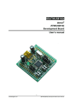
horizontal speed of the helicopter is controlled by changing the pitch and therefore
creating a resultant force forwards or backwards as shown in Figure 2.1.
Figure 2.1: Helicopter Flight Vectors (from [24])
3
Section 2 Literature Review
2.1.1
4
Stabiliser Bar
Roll control on the chosen helicopter is achieved with a stabiliser (or balance) bar
which changes the cyclic pitch of the main rotor. This is a purely mechanical system
and makes the helicopter resistant to changes in angle of bank. The stabiliser bar
works similarly to the Bell-Hiller system used on some full sized helicopters [21].
However, rather than mixing the stabilising action with a control input the cyclic
pitch is only controlled by the stabiliser. By placing a small weight at both ends of
the stabiliser bar and connecting it to the motor shaft it acts as a gyroscope when
the main rotor is spinning. A gyroscope resists any motion in the plane of rotation
and when the helicopters angle of bank changes the stabiliser bar is at a different
angle to the motor shaft resulting in a cyclic input correcting the unwanted roll [16].
2.1.2
Motor Control
The original controller on the chosen helicopter, used for manual remote controlled
flight, used pulse width modulation to control the motors as it provides a way
to control the amount of power delivered to the motors with a digital signal [32].
Varying width pulses are sent to the motor which results in an amount of power
delivered to the motors proportional to the width of the pulse. Also, a switching
circuit will need to be designed as a microcontroller will not be able to supply
sufficient current to drive the motors.
2.2
Sensor Data Reading and Processing
Two sets of data are necessary to control the helicopter and retrieve data about
the environment. The attitude of the helicopter is the representation of its rotational position compared to a reference frame and combined with the linear position
provides sufficient information to determine the helicopters position in space.
The attitude of a body is defined as the difference between the bodies frame and
the reference (fixed) frame which for the purpose of this project is taken as the
earth [26]. There are different methods of representing the rotations that define the
attitude with their own advantages and disadvantages. Euler angles correspond to
the angles of rotation directly but are dependent on the order applied and contain
singularities at the extremes of rotations. Both quaternions and direction cosine
Section 2 Literature Review
5
matrices solve these problems. The representations and their relation to each other
are shown in Figure 2.2.
ex
given a rotation of axis → e = ey and angle = θ
ez
q1
q1 = ex sin 2θ
q2 q2 = ey sin θ
2
Quaternions → q =
q3 q3 = ez sin θ
2
q4
q4 = cos 2θ
Rotation matrix → R =
ex ey (1 − cos θ) − ez sin θ ex ez (1 − cos θ) + ey sin θ
cos θ + e2x (1 − cos θ)
ey ex (1 − cos θ) + ez sin θ
cos θ + e2y (1 − cos θ)
ey ez (1 − cos θ) − ex sin θ
ez ex (1 − cos θ) − ey sin θ ez ey (1 − cos θ) + ex sin θ
cos θ + e2z (1 − cos θ)
Figure 2.2: Rotation representations
It is possible to build up rotation matrices directly from sensor data as shown in
[26]. Once the attitude is represented in the form of a rotation matrix (or directional
cosine matrix) it is possible to retrieve the roll, pitch and yaw angles by performing certain dot or cross products which only require multiplication and addition,
significantly reducing the computation time when performed on a microcontroller.
Quaternion or Euler angle representation would require trigonometric calculations
resulting in a significant delay.
As the helicopter used has mechanically controlled roll only the pitch and yaw angles
vary. Therefore the full rotational representation is not needed as the controller can
act solely on these two angles. Although Euler angles have singularities at the
extremes of rotation this does not matter significantly due to the lack of movement
about the roll axis. The values of pitch should not vary by more than a few degrees as
beyond small values of pitch the helicopter will become unstable. The singularities
will be relevant for the heading (yaw angle) as when at a heading of 180◦ there is a
sudden change from +180◦ to -180◦ . Due to the design of the helicopter each axis
has little effect on the other axes and so this singularity can be dealt with by the
controller as it only exists for one specific case.
3. Design Choices
The choice of components for the autopilot was, in part, influenced the the components used by the original controller of the helicopter, as they were known to work
with the chosen helicopters motors and battery.
3.1
Helicopter
There are three main types of remote control helicopter available as shown in Table
3.1. The cost of a helicopter is usually closely related to the power of the rotors
and so therefore the helicopters carrying capacity.
No. of Channels Up/Down
Yaw
Pitch
2
X
X
3
X
X
X
4
X
X
X
Roll
Cost and Capacity
Low
Medium
X
High
Table 3.1: Comparison of different types of helicopter
Two channel helicopters were initially investigated as they are the lowest cost RC
helicopters available, however they are mostly limited to a carrying capacity of a
few grams. Even if a more substantial 2-channel helicopter could be found there is
no control of pitch available as they instead rely on always travelling forward at a
fixed speed which would require complex control in order to be used for a practial
application.
As four channel helicopters do not have the mechanical stabilisation of roll found on
three channel helicopters a complex controller is needed as both pitch and roll have
to be stabilised electronically. Also, a movement in one axis will influence the other
axes further increasing complexity. Despite the greater flexibility of a 4-channel
helicopter and increased carrying capacity the greater complexity and cost mean
that it would not entirely be in line with the project goals.
A three channel helicopter was chosen as it offers the best balance between flexibility
and cost, it was decided that the inability to correct lateral movement could be
overcome and was not sufficiently disadvantageous to justify increasing cost. There
6
Section 3 Design Choices
7
are two common designs of three channel helicopters, coaxial helicopters which have
two contra-rotating rotors on the same axis and tandem helicopters which have
counter-rotating rotors mounted on different axes on the body of the helicopter.
Helicopters of a coaxial design are more common and so it was easier to find one
of a suitable cost and carrying capacity and hence a coaxial helicopter was used for
this project.
3.2
3.2.1
Microcontroller
Choice of Microcontroller
There were three microcontrollers considered for being used for the autopilot, either
an 8-bit AVR or PIC or an ARM based microcontroller.
Both 8-bit microcontrollers are comparable in terms of processing power and onboard peripherals and although the processing power is limited compared to an
ARM based microcontroller, development is easier due to greater familiarity, specifically with AVR microcontrollers. It was decided that due to the existence of projects
such as Ardupilot [4] which uses an AVR based controller, the added complexity of
an ARM based microcontroller would not be needed.
The use of an AVR microcontroller was decided on as it offered more on-board
peripherals than PIC microcontrollers, for example the PIC16F874 [22] has two
PWM outputs while the ATmega8 [9] has three PWM outputs. The requirements
of the project could therefore be met with a lower complexity AVR than a PIC.
Also, it had the benefit of added familiarity with the architecture and development
tools.
3.2.2
Program Design
As the autopilot is controlling the helicopter in flight it is particularly important that
it can respond in a timely fashion to irregular events, whether they are commands
from the ground station or changes in the sensor data which indicate the need for
action to return to the desired attitude. For this reason the program running on the
autopilot would be designed like a state machine as this would improve its ability
to respond to incoming events of different types. Incoming events would result
in interrupts being triggered on the microcontroller and so flags could be used to
Section 3 Design Choices
8
signify the presence of events to the main state machine which would then be dealt
with when the processing of other previous events had finished.
In order to stabilise the helicopter a closed loop controller would be needed and
so a discrete proportional-integral-derivative (PID) controller would be used. The
sampling rate of the sensor data would determine the sampling rate used for the
PID algorithm. A PID controller was chosen due to familiarity with techniques for
their design and testing as well as examples that demonstrated that such a controller
could be implemented on an AVR, such as Atmel application note ’AVR221’ [6].
3.3
Circuit Board
3.3.1
Type of Board
The construction of the circuit board used to mount the components on the helicopter was important as weight is an important factor due to limited carrying
capacity. Also, ideally the board would be low cost to further reduce expense.
Two main options were available for use, stripboard and printed circuit boards.
With printed circuit boards there was either the option of small scale, milled or
etched (toner transfer method) boards, or a commercially produced circuit board.
Type
Design Time
Manufacture Time
Weight
Cost
Stripboard
Low
High
High
Low
Milled PCB or
Etched PCB
High
Low
Low
Low
Commercial PCB
High
High
Low
High
Table 3.2: Comparison of different types of circuit board
Table 3.2 shows the advantages and disadvantages of the different types of boards.
Weight and cost were the most important factors for the project and so neither
stripboard or commercial PCBs were suitable. Stripboard is not particularly space
efficient and would require the use of through hole components, significantly adding
to the weight of the autopilot. A commercial PCB would increase the cost of the
autopilot too much for prototyping but would be suitable as a way to implement
a finished version as commercial PCBs are more suited to volume production than
prototyping.
Section 3 Design Choices
9
The decision was made to use an etched PCBs as it had some advantages over
a milled PCB. The etched boards could have smaller traces as the process was
limited by the resolution of a printer rather than the mechanical precision of a
2
inch could be produced [31]
CNC machine. Theoretically traces down to around 300
but this was far smaller than needed for the autopilot. The toner transfer method
did have the disadvantage of not always producing well defined traces, but any
problems could be determined before any copper was removed.
4. System Implementation
4.1
Initial Microcontroller Experimentation
Initially the environment needed to program the AVR was set up, breadboard was
used to allow rapid prototyping of different circuits which were then transferred
to a PCB for the final design. During this stage it was verified that the AVR’s
three PWM outputs could be used independently to control all three motors. The
AVR was programmed using C, compiled with avr-gcc as although less efficient than
assembly it offered quicker development.
4.2
State Machine
Due to the reasons stated in Section 3.2.2 the program was designed in the style
of a state machine. Sensor data and command input is interrupt based and the
interrupt service routines (ISRs) were designed to store the data for processing in
the main state machine. This required the use of a status register so different parts
of the program could be notified of the presence and source of new data, a control
register was also utilised so that different modes of operation could be supported.
The contents and operation of the registers are explained in Appendix B.
The C preprocessor was used to simplify the use of the status and control registers.
Each bit was defined and accessed by name so it was clear which bit was intended
and this also allowed re-ordering of the registers without changing the rest of the
program. Macros were written to allow each bit to be set, cleared and checked
individually which also ensured that the registers were accessed in a consistent way
(as shown in Listing G.1).
Figure 4.1 shows the design of the state machine. Each state in the state machine,
and the ISRs, were designed to be run as quickly as possible so that the timing
was as consistent as possible with data arriving asynchronously. The processing
of data, which occurred in the ST INT COMMAND (internal command processing) state, was the most computationally complex component of the program as
it involved floating point arithmetic which is not supported natively by the AVR
microcontroller and hence required more clock cycles to perform the calculations.
10
Section 4 System Implementation
11
The sample rate for the sensors had be calculated (as shown in Section 4.6) to ensure that there were still sufficient processor cycles available to process commands
before more sensor data needed to be calculated.
Figure 4.1: State Machine - Main Program
4.3
4.3.1
Communications
Wired Communications
A wired link was initially used for debugging and control of the microcontroller.
The link was between the UART (universal asynchronous receiver/transmitter) on
the AVR and a USB-to-Serial converter on the ground station (a laptop running
Linux). The use of a communications protocol allowed the link to more easily
transfer different types of data. The protocol is explained further in Appendix C
and the commands are described in Appendix D.
4.3.2
Wireless Communications
The same communications protocol was used for the wireless link between the
ground station and the autopilot but a simple ASK transmitter/receiver pair was
used which only allowed one-way communication from the ground station to the
autopilot. The ground station only needed to receive information for further processing which could take place over a wired connection at the end of each flight.
The limitations of a one-way link were justified by reducing the complexity of the
Section 4 System Implementation
12
autopilot. This also meant that many of the commands, those responding to the
ground station, were no longer needed.
The receiver on the autopilot was limited to a data rate of about 2400 bps [29] which
was significantly slower than the previous wired link. Also, the receiver requires
frequent transitions between ’0’ and ’1’ to synchronise itself with the transmitter.
In order to provide this synchronisation framing was added around each byte of a
sent command and the ground station would continuously transmit alternating 1’s
and 0’s (’U’ in ASCII) while there were no commands to send. A state machine
(Figure 4.2) was added to the UART ISR to process this framing and place the
received command into a buffer.
Figure 4.2: State Machine - UART Reading
The framing ensured a minimum number of transitions per byte of each command.
As before, the state machine would stay idle until it detected a start character however the length of commands was fixed to 8 bytes for the wireless communications
link as, due to the inherent unreliability, it was possible for a character to be lost
and if the byte signifying the end of the command was lost it could cause further
problems as the state machine would continue to try to read in the command until
the next stop byte was received.
Section 4 System Implementation
4.4
13
User Interface
A graphical user interface was written to control communications between the
ground station and the helicopter. The code for the user interface was, in part,
generated using QT Designer [2]. The code for the backend of the user interface
was written in C++ using the QT UI library, allowing the reuse of C code, such
as the defaults for the control register. The initial design of the interface is shown
in Figure 4.3 and was designed for two way communication between the autopilot
and ground station. When the communications link changed to being a one-way
wireless connection the user interface was redesigned to better suit the new requirements. Both versions of the user interface allowed commands to be easily sent to
the autopilot by taking care of the communications protocol.
Figure 4.3: Serial communications user interface
The second version of the user interface, as shown in Figure 4.4, was primarily
used to send commands as there was only one-way communication from the ground
station to the autopilot. The second version of the user interface gave easier access to
common commands and features of the autopilot. The state of the control register is
shown in the interface and toggling any of the bits will send the relevant command,
also a section was added to allow the magnetometer to be more easily calibrated.
Buttons were also added both for common commands and also to set the relevant
command byte characters, for example ’Prepare 2’ would put ’p’ into both ’c1’ and
’c2’ to set pitch PID constants (Appendix D).
For later testing of the autopilot it was planned to control the helicopter manually
and then test PID control of each of the axes separately. This would allow individual
tuning of each PID controller which would simplify testing. In order to allow manual
Section 4 System Implementation
14
Figure 4.4: Serial communications user interface - second version
control of the helicopter input from a joystick to the ground station was needed
as keyboard control would not offer sufficiently precise control to be able to fly
the helicopter. To achieve joystick control values were read from a Playstation 3
’Sixaxis’ controller. The values of the joystick were read every 115 ms (to allow
sufficient time for the necessary commands to be sent to the autopilot) and sent to
the helicopter as values of lift, yaw and pitch.
4.5
Transistor Circuits and Motor Control
The maximum current supplied by any individual pin on the AVR is 40 mA [8] and
the helicopter was found to need ≈ 1 A for the main rotors and ≈ 0.2 A for the
tail rotor. To deliver the needed current a NMOS transistor was used to switch the
power to the motor, with the gate connected to the PWM outputs of the AVR so
that motor current depended on the PWM duty cycle. Transistors with low Ron had
to be chosen as the equivalent resistance of the motors was very low and a voltage
divider existed with the motor and transistor, giving a voltage across the motor
Rmotor
of Vmotor = Rmotor
V and so Ron needed to be minimised to minimise power
+Ron dd
lost to the MOSFET. The tail rotor required an H-Bridge to change the direction
of the motor and effect positive and negative changes in pitch. The design of the
H-Bridge was adapted from [10] and pull-up resistors were added to the direction
signals to ensure that the H-Bridge would be in a known state even if the gates
Section 4 System Implementation
15
were un-driven. A PWM frequency of 3.125 kHz was chosen as it was close to the
frequency used by the original controller (2.27 kHz).
To ensure that the chosen transistors would be able to switch sufficient current to
control the motors transistors with similar characteristics to the transistors used on
the helicopters original control board were chosen. Particular attention was given
to the ratings for maximum current and Ron values. The final schematic of the
motor control circuitry is shown in Figure E.3. Also, although the rating of the
MOSFET’s body diode was sufficient to protect the transistor from spikes caused
when the motor is switched off, the circuit requires a further protection diode to
carry the excess charge to ground and prevent excessive changes to the supply
voltage.
The AVR could control the speed of the three motors by changing the PWM duty
cycles, and could control the direction of the tail rotor by two outputs (DIR1 and
DIR2) which were connected to the H-Bridge. Initially the motors were controlled
directly but due to the coaxial design of the helicopter it was desirable to have
two modes of operation, directly driving the motors and ’calculated’ control where
values for lift, yaw and pitch were used to calculate the needed motor inputs as
shown in Figure 4.5. The C implementation of the calculated mode is shown in
Listing G.5. The calculated control takes inputs from both the ground station and
the PID controller and these different modes are selected by the control register as
shown in Table B.1.
M otorM ain = Lif t + Y aw
M otorSecondary = Lif t − Y aw
M otorT ail = |P itch|
(Where all three values are restricted to a range of 0 → 255)
DIR1 = P itch > 0, DIR2 = P itch < 0
Figure 4.5: Calculations to control motors from heading data
4.6
Sensor Data
Initially the autopilot used the Dimension Engineering DE-ACCM3D (which contained an ADXL330 accelerometer), allowing the tilt of the helicopter to be determined for both the roll and pitch axes. This allowed control of the pitch axis
but additional sensors were needed to control the heading. A three axis gyroscope
would give measurements for the rate of change of heading, as well as pitch, but
Section 4 System Implementation
16
due to numerical errors [26] a reference for the heading was also needed which could
be provided by a three axis magnetometer. Using three separate sensors would
add weight to the autopilot and so for the final design the Sparkfun SEN-10321
’Sensor Stick’ was used which provided an accelerometer (ADXL345), a gyroscope
(ITG-3200) and a magnetometer (HMC5843) all of which were three axis sensors.
The AVR was used to communicate with the I2 C interface to the sensor stick. Peter
Fleury’s I2 C library [14] was used to control and read the sensors and wrapper
functions were written to simplify the reading of each sensor as they all had similar
requirements for reading. All three sensors output 16-bit signed integers (in two’s
complement format) which could be directly used for calculations in C but required
extra cycles to compute as the AVR is only an 8-bit processor.
The sample rates varied between the sensors but the magnetometer had the lowest
sample rate at a maximum of 50Hz [17]. One of the AVR’s timers was set up to
allow the sensors to be read at a fixed time interval by causing an interrupt to be
signalled regularly. In order to make sure the sensors were read at a fixed interval
the communications between the AVR and the sensors took place within the ISR.
At an I2 C clock of 100 kHz it takes 810 µs to read all three values from one sensor
(including protocol overhead there are 81 bits communicated) so to read all three
sensors would take 2.43 ms. As the UART operates at 2400 bps each byte takes
3.3 ms to transmit, meaning the UART ISR is triggered every 3.3 ms. If interrupts
are disabled, such as within an ISR, for over 3.3 ms the UART ISR will not be
run and characters will be lost, and although there is sufficient time to read all
sensors within the time for one UART character other parts of the program may
delay the running of either ISR. For this reason each sensor was read individually
and a simple state machine (Figure 4.6) used to determine which sensor to read
next. Each sensor would be read with the same time interval, but with a small
offset between sensors.
Figure 4.6: State Machine - Timed Commands / Reading of Sensors
Section 4 System Implementation
17
The sensors were read every 15 ms (with the interrupt being called every 5 ms) to
give a sample rate of 66.7 Hz. This was higher than the maximum sample rate of
the magnetometer (50 Hz) and so no more gains from increasing sample rate could
be achieved for heading control. The accelerometer and gyroscope had a greater
sample rate but the same rate was used for all sensors to simplify the autopilot,
with the ability to increase the sample rate later if necessary.
Figure 4.7: Calibration of magnetometer
Due to the positioning of the magnetometer and the motors, as shown in Appendix
F, the magnetometer required calibration as the permanent magnets in the motors
introduced a constant offset. Magnetometer readings were taken at the four cardinal
directions in order to record minimum and maximum values for both the horizontal
axes which could then be used to calculate the range and offset and normalise the
data (Figure 4.8) using a similar method to Microchip application note ’AN996’
[23]. The cardinal directions were indicated by a compass rose that was drawn up
using a hand-held compass as a reference as shown in Figure 4.7. The magnetic
field from the motors also caused the readings to overflow so the range had to be
increased to ± 2.0 Ga to allow the heading to be calculated while reducing the gain
as little as possible to keep higher resolution. The calibration data was stored in a
C struct which could be saved to the AVR’s EEPROM memory so it did not require
re-calibration after the autopilot had been restarted. The code used to calibrate
the magnetometer is shown in Listing G.4.
Although the offset introduced by the motors is constant while the motors are off
and the helicopter is standing on the ground, the magnetic fields change once current
is flowing through the motors. There is little that can be done to remove this effect
and so inaccuracies will be introduced into heading control. Also, although the
magnetometer provides three axes of data there is no tilt compensation performed
Section 4 System Implementation
18
Nrange = Nmax − Nmin
− Nmax
Nof f set = Nrange
2
M agnN (cal) =
(M agnN +Nof f set )×200
Nrange
(Where ’N’ represents the X or Y axis)
Figure 4.8: Calculations to normalise magnetometer readings
as the helicopter used will be unstable if the pitch or roll exceeds a few degrees.
The stabiliser bar should prevent roll however the pitch PID controller will need to
be able to prevent significant unintentional pitching movements.
4.7
PCB Design and Manufacture
All the circuit boards for the project were manufactured using the toner transfer
method as described in [15] and [31]. Initially the plan was to split the autopilot
across separate boards so that different parts of the autopilot could be redesigned
and remade without having to remake the entire autopilot. This would also allow
versions of each board to be designed to use both through-hole and surface components as available and needed. The through-hole version of the autopilot proved to
be too heavy for the helicopter to be able to fly but it still provided a way to test
the functionality of both the circuit design and the PCB design.
Different areas of the circuit board needed different voltages and so the design had
to include voltage regulators to provide both 3.3 V (needed by digital components)
and 5 V (needed for the RF receiver). As the helicopter’s battery was only rated
for 3.7 V the voltage had to be stepped-up for the wireless receiver which was
not ideal but provided a way to use a simple and inexpensive wireless link as the
majority of similar receivers also required a 5 V supply. A voltage divider was also
needed to step-down the 5 V output of the wireless receiver to 3.3 V for the AVR’s
UART. Also, the AVR programmer used to program the autopilot used 5 V and so
a method to disconnect the AVR from the rest of the circuit for programming had
to be designed into the PCB. This was achieved by using a jumper to connect the
AVR to the autopilot’s 3.3 V supply which could also be used as a connection point
for 5 V for programming.
Section 4 System Implementation
19
The first testing that included driving the main motors of the helicopter used surface mount components and was split into two boards, one for the majority of the
autopilot and one for motor control, provisions were made for power distribution
but proved to be insufficient. The traces for the power supply were made as wide as
possible so they could carry sufficient current and decoupling capacitors were added
for each integrated circuit used. At a low PWM duty cycle little current would be
drawn and the autopilot would function as expected but at a higher duty cycle, and
therefore higher current, the power supply would not be sufficiently stable and this
would be made apparent by the microcontroller resetting. Further investigation was
therefore undertaken as to how to further decouple different areas of the autopilot.
4.7.1
Power Supply Decoupling
The circuitry for the autopilot is split into three main areas as shown in Table
4.1. Both the digital and motor control circuitry contribute ripple to the power
supply, which reduces the accuracy of the sensors as they require a stable supply.
The digital circuitry (the microcontroller) adds high frequency (8 MHz) but low
magnitude spikes as it only draws current on the edge of the clock signal [7] while
the motors will contribute a larger ripple but at the PWM frequency (3 kHz) which
is lower than the microcontroller clock frequency. The large currents drawn by the
motors at high PWM duty cycles caused ripple on the supply which exceeded the
operating limits of the digital components. This meant that it was important to
isolate the different areas of the autopilot as much as possible and the autopilot
circuit board was redesigned with power distribution as a priority.
Area of Circuit
Analogue Circuitry (Sensors)
Digital Circuitry
Motor Control
Requirements and Impacts
Very stable supply
Low current draw
Few spikes or ripple
Relatively stable supply
Current drawn in short spikes
No supply requirement
High current draw in spikes
Table 4.1: Different areas of circuitry for autopilot
As the functionality of the basic circuits had been verified the autopilot was designed
as a single board as it offered more opportunities for decoupling and reduced the
overall weight. Due to earlier problems as much space as possible for decoupling
Section 4 System Implementation
20
capacitors was added for each component, the autopilot could then be tested and
further capacitors could be added later to help decoupling if needed. Decoupling
was also added to the supply as described in Lattice technical note ’TN1068’ [27] to
provide power during short high current demands. Atmel application note ’AVR042’
[7] states that in high noise situations the internal pull-up resistor on the RESET
pin may not be sufficient and so space was provided for an external pull-up resistor
in case this proved to be a problem. Both TN1068 [27] and AVR042 [7] described
the use of a low-pass filter (using an inductor and a capacitor) to improve the
decoupling where there are significant current spikes. A low-pass filter was placed
to isolate the supply to the motors from the supply to other components, a jumper
was added to be able to bypass the low-pass filter for testing without driving the
motors and to be able to observe if the filter had any impact on performance.
The power distribution for the circuit was designed in a star topology as this would
help prevent noise and ripple from one component affecting other components [32].
As the circuit board was only a single-sided board it was not entirely possible to
isolate the ground for each component but only the sensors and the wireless receiver
directly shared a ground trace. Ideally two ground planes would be used, one for
the motors and one for all other parts of the autopilot, as the use of a ground plane
would assist in the decoupling of components while the high ripple caused by the
motors would require a separate ground plane for further isolation. A circuit board
using a ground plane was designed but was found to reduce the effectiveness of the
toner transfer method as solid blocks of toner would not transfer well to copper clad
board and so care was taken to design the ground distribution to compensate for
the lack of a ground plane.
The original controller for the helicopter used resistors between the driving pins and
the gates of the MOSFETs, this helps to reduce ringing caused by resonance within
the gate drive circuit [30] and so resistors were added between the PWM outputs of
the AVR and the gates of the MOSFETs. Once the design was otherwise finished
as many extra connection points were added as there were space for to allow the
autopilot to be extended, this also allowed easier debugging as a spare I/O pin could
be used to output a signal to show the state of the autopilot.
4.8
PID Controller
Figure 4.9 shows the flow of the sensor data through the autopilot, the first step is
to calculate the current attitude of the helicopter. The decision was made to treat
Section 4 System Implementation
21
each axis (pitch, roll and yaw) independently as due to the particular design of
helicopter a change in one axis will have very little effect on the other axes, this is
because roll is fixed by the balance bar and so any horizontal translational motion
is exclusively controlled by changes in the angle of pitch. This is in contrast to
fixed-wing and other rotary-wing aircraft where both roll and pitch have an effect
on horizontal motion.
Figure 4.9: Flow of data through autopilot
Figure 4.10 shows the labelling of the sensor axes. The current angle of pitch could
be measured using the accelerometer readings for the Z-X plane, the sensor would
detect a constant acceleration of 1 g due to gravity which would always be directed
downwards in the reference frame. By measuring the difference between the detected
acceleration and the expected acceleration the angle of pitch could be determined.
In a similar way, the Earth’s magnetic field provided a reference for the angle of yaw
and so the angle between the detected magnetic field in the magnetometer’s X-Y
plane (after calibration) and the expected field would give a value for the current
heading of the helicopter.
Inverse trigonometric functions from the avr-libc library were used to calculate
the angles. The calculated angles comprise the measured attitude which can then
Section 4 System Implementation
22
be compared to the desired attitude so that the PID controller can calculate the
correct restorative action to return the helicopter to the current desired attitude.
Each calculation would be performed after the reading of the sensor but before the
next sensor had been read. The time for an inverse trigonometric function was
measured to be in the range 130 µs → 240 µs, or 1040 → 1920 cycles, although this
would depend on the ease of calculation for the input values and is only a rough
estimate but still shows the significant amount of processing time allocated to the
calculation of angles.
The implementation of the PID controller was, in part, adapted from Atmel application note ’AVR221’ [6]. The constants for the controller, as well as the cumulative
sum of the error, were stored in a single data structure as shown in Listing G.2. The
PID controller (Listing G.3) took the measured and desired values as well as the
PID data structure and calculated the necessary motor output as well as updating
the data structure with the new cumulative sum. This function also prevented the
integral term from growing too large by limiting the magnitude of the cumulative
error. The derivative term of the controller was directly taken from the gyroscope
as this provided a way to benefit from the quicker response of the gyroscope without implementing Kalman filtering to combine sensor data which would increase the
complexity of the autopilot. Also, if the derivative term was based on the calculated
rate of change of the error then any changes in the desired attitude would result in
“an unwanted rapid change in the control input” (AVR221 [6]).
Figure 4.10: Orientation of sensor stick with respect to helicopter (from [28])
The same code for the PID controller could be used to control both the pitch and
the heading of the helicopter by changing the sensor data passed to the controller,
simplifying the implementation. The output of the PID controllers was combined
into data for the ’calculated’ control mode and so it was possible to enable or disable
Section 4 System Implementation
23
each PID controller separately using the control register to allow individual testing
while the other axes were controlled manually.
4.9
Environment Mapping
The sensors used for environment mapping were ultrasonic distance sensors produced by Maxbotix [20]. By combining the data known about the position of the
helicopter with distance readings it is possible to build up an image of the surrounding environment. Also, the distance gives an indication of the linear position of the
helicopter relative to its environment and so helps to locate the helicopter in space.
The sensors provided multiple ways to read the distance data, and in this case the
analogue output was read by the AVR’s ADC. The C ADC bit in the control register
controlled if the ADC was currently taking readings or not. As with other data, the
readings were read from the ADC in an ISR into a global variable. The distance
readings did not require any processing and so no provision was made to indicate
the presence of new distance data using the status register. Also, a command was
added to the communications protocol to allow the distance data to be saved to
EEPROM for later analysis.
5. System Testing and Results
The basic functionality of each part of the autopilot was tested during prototyping
to verify its operation, the functionality was further checked once the system was
more assembled so that the interaction between parts of the system could also be
verified.
5.1
Power Supply
After the multiple board version of the autopilot had problems with decoupling
the first area of the single board version to be tested was the power supply and
decoupling between different areas of the board. The design had multiple points
where the supply rails could be disconnected so the ripple and spikes caused by the
motors could be observed without any possibility of damaging other components.
A signal generator was used to apply a signal to the gate of the MOSFET which
was equivalent to the PWM that would be applied by the AVR. The positive supply
rail was then observed (shown in Figure 5.1) showing that the motors, when driven,
introduced significant ripple to the supply as well as short spikes at the start and
end of each pulse to the gate, this was observed before any decoupling capacitors
were added to the board to provide a reference for the effect that the additional
decoupling efforts had.
After additional decoupling capacitors were added to the autopilot the supply was
then measured in the same way as before and it was observed that significant ripple
was still present on the digital supply as well as short spikes. An inductor was
therefore added between the supply to the motors and the supply to the digital
circuitry to further reduce the spikes. Figure 5.2 shows an close-up view of the
effect that the low-pass filter had on the spikes on the supply. The maximum
voltage now reached is ≈ 4.7 V which is within the limits of other components and
is significantly less than the spikes shown in Figure 5.1 which in some cases had a
magnitude of over 7 V, although the exact magnitude of the spikes was difficult to
determine due to their short duration. These spikes were due to flyback from the
motors, so it appeared that the protection diodes used were insufficient as they did
not appear to react sufficiently quickly to entirely remove the voltage spike despite
having an almost identical rating to the diodes used for the original controller of
24
Section 5 System Testing and Results
25
Figure 5.1: Positive supply rail measured at motor
the helicopter. After the low pass filter had been added, however, the spikes were
reduced to sufficiently low levels as to not cause further problems. Also, the pull-up
resistor for the RESET pin was not needed as the isolation between parts of the
autopilot proved sufficient.
Figure 5.2: Positive supply rail measured at digital supply (with additional
decoupling)
Section 5 System Testing and Results
26
The signal at the gate of the MOSFET was observed to confirm that the gate resistor
had no impact. Figure 5.4 shows a comparison of the PWM signal being applied
directly and through the gate resistor. The rise time increased slightly from 140 ns
to 150 ns but there was little overall impact, also, 150 ns is a small proportion of
the PWM period of 320 µs.
The time constant for the RC circuit formed by the gate resistor and gate capacitance was calculated for both the original controller and the autopilot as shown
in Figure 5.3. This shows that the time constant is less for the autopilot and so,
although other parts of the original controller’s drive circuit are unknown, the autopilot should be able to sufficiently drive the MOSFET gate.
τ = RC = 330W × 1000pF = 330ns τ = RC = 10W × 1350pF = 13.5ns
(a) Original Controller
(b) Autopilot
Figure 5.3: MOSFET gate RC time constant
(a) PWM signal applied directly to gate (140 ns)
(b) PWM signal applied through resistor (150 ns)
Figure 5.4: MOSFET gate rise time
Each of the different voltage rails were also tested to check that they were able
to provide a stable supply at the correct voltage. This made sure that while the
autopilot was operating all parts of the circuit would still function correctly. Although the decoupling did not stop all ripple on the power supply the use of voltage
regulators prevent the ripple being present on the supply to the digital components.
The final version of the PCB used copper clad board with a thin substrate which
reduced the overall weight of the autopilot. The thinness of the board meant it
was flexible, which resulted in bad solder joints at the MOSFETs used to control
the motors. This meant that occasionally the board would require flexing for the
motors to be turned on.
Section 5 System Testing and Results
27
The weight of the helicopter was measured in its original form and also with the
autopilot to compare the difference. The original weight of the helicopter was 140
g which was less than the weight with the autopilot (at 143 g), however, being
designed as a toy remote control helicopter there was an amount of material that
had solely aesthetic purpose and so could be removed to reduce the weight. This
allowed the total weight of the system to be reduced to 135 g, less than the original
weight.
5.2
Remote Control
The wireless communications required testing to ensure that there was sufficient
synchronisation between the transmitter and the receiver for a reliable communications link. Figure 5.5 shows the improvement achieved when both framing and
continuous transmission were used for the communications link, the pulses are much
more defined and so it is more likely that they will be correctly read by the UART
on the AVR. While commands could be received by the autopilot without framing
it was not sufficiently reliable, especially to provide remote control of the helicopter
in flight, as most of the time the commands would be received incorrectly. Framing
provided sufficient reliability that the parity, and other validation provisions within
the protocol, did not need to be implemented.
(a) Without framing
(b) With framing
Figure 5.5: Effect of framing on RF receiver synchronisation
Once reliable communications were possible between the autopilot and the ground
station the joystick control mode of the helicopter was tested. The first flight test
of the helicopter showed a constant yawing motion present when both main rotors
were driven at the same PWM duty cycle. This was because the balance bar meant
Section 5 System Testing and Results
28
that the characteristics of both rotors were different, resulting in different speeds
when driven by the same amount. The difference in speed caused a resultant torque
and so a yawing motion. This rotation around the vertical axis could have been
corrected by introducing an offset into the yaw calculations but would be corrected
by the controller once implemented.
The remote control showed that control of the helicopter was possible with updates
sent to the motors every 115 ms, an update rate of 8.7 Hz. However, it was evident
that this was near the lower limit of the update rate as the delay in response to
inputs could be observed while flying the helicopter, making control more difficult.
The PID controller would be unable to make the same corrections possible with
manual control so it would probably require a quicker update rate to successfully
stabilise the helicopter but gave a rough upper limit to the time between motor
updates. As the sensors were read, and the necessary calculations performed, at a
rate of 66.7 Hz the update rate should be sufficiently high to allow satisfactory PID
control.
5.3
PID Tuning
The design of the helicopter meant that each axis of rotation had little impact on
other axes and so each PID controller only had to control one axis. This independence also meant that the testing and tuning of each PID controller could occur
separately.
5.3.1
Pitch Control
For flight the helicopter is supported by lift generated by the main rotors and so
by suspending the helicopter at a central point the dynamics of the pitch axis
could be investigated in a consistent and reliable fashion while giving the same
characteristics as during flight. By being placed in a fixed position the angle of
pitch could be measured by video by putting a backdrop with angles marked as
a reference (Figure 5.6). The pitch axis is inherently stable as the weight of the
helicopter will return the pitch axis to a fixed angle however a quicker response
was required to prevent unwanted movement forwards and backwards. Also, pitch
control is necessary to achieve controlled movement.
Section 5 System Testing and Results
29
Figure 5.6: Pitch PID tuning setup
The measurements were made by pushing the pitch axis to an offset of 20◦ , greater
than any disturbance that should be encountered in flight but would make measurement easier, and recording the resultant motion when released. The number
of frames from the start to a maximum oscillation of 5◦ were counted to give a
value for the settling time. To provide a control, four videos were taken with the
motors off. The autopilot was then used to control the pitch axis and the ground
station used to change the PID constants between tests. Each controller constant
was changed independently so its effect could be observed to help direct the tuning.
Proportional control appeared to reduce the stability of the pitch axis, increasing
the settling time from ≈ 6.3 s to ≈ 17.9 s, this showed that a P controller was
insufficient and so the derivative and integral terms were necessary. The derivative
term rapidly improved the dynamic response of the helicopter, eventually reducing
the settling time to 0.8 s, but further increases did not result in any changes to
the characteristics. Adding a small amount of integral control removed the steady
state error present without having any apparent effect on the settling time, however,
increasing the integral term resulted in a deterioration of the dynamic response.
PID constants of Kp = 15, Ki = 1 and Kd = 100 gave a settling time of ≈ 0.8 s.
While this is a significant amount of time to take to return to the desired attitude it
is the result of an initial displacement of 20◦ which is very unlikely to be encountered
in normal flying conditions. The tail rotor did not appear to be powerful enough to
improve on this response as it had to overcome the inertia of the helicopter.
Section 5 System Testing and Results
5.3.2
30
Heading Control
Testing of the heading PID controller was more difficult than the pitch control, as
any method of suspending the helicopter would introduce friction and so change the
system dynamics. The testing method used was to change the constants while the
helicopter was landed and then to use the remote control to briefly fly the helicopter,
observing the resulting stability. Control of pitch was given to the PID controller
as it was demonstrated that it could provide stable control. The judgement of the
stability was mainly subjective but a few objective observations could be made,
increasing the proportional or derivative terms too far would result in overshoot
and ringing which was visible as rapid oscillations in the heading. The removal of
ringing showed an objective improvement in the heading control but other changes
to the constants had little noticeable effect on the dynamic response, reducing the
opportunities for further optimising the controller. Values of Kp = 1, Ki = 1 and
Kd = 10 appeared to give stable control of the heading without causing ringing.
5.4
Environment Mapping
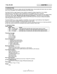
For the initial testing of the autopilots environment mapping capabilities the helicopter was suspended in the middle of a room and allowed to turn freely about the
yaw axis. As the helicopter was rotated, readings from the distance sensor, as well
as the current heading, were saved into the AVR’s EEPROM memory. Once a number of readings had been taken the data was retrieved and plotted to give an image
of the surroundings as sensed by the autopilot. Figure 5.7 shows the results that
were obtained. As it was only an initial test, no efforts were made to ensure equal
spacing of the readings and so some areas didn’t have any data obtained. The data
did show the outline of the room but due to apparent noise in the measurements the
distances to the walls varied by about a metre. The resulting graph shows the need
for averaging or further filtering of the data to give a useful model of the helicopters
surroundings. Although the readings taken were not acquired while the helicopter
was in flight the same methodology could be applied.
Section 5 System Testing and Results
Figure 5.7: Environment Mapping - Initial Test
31
6. Evaluation
6.1
Fulfilment of Scope
Control of helicopter by microcontroller
The autopilot was able to fully control the three motors of the chosen helicopter, providing speed control to all motors. The tail motor could also be
driven in both directions, necessary to fully control the pitch of the helicopter
and so provide control of forwards and backwards motion. Different control
modes of the motors were implemented, allowing both on-board control and
remote control for different purposes.
Communication between the helicopter and a ground station
A communications link was implemented between the ground station and the
autopilot, however, it was only able to send commands to the autopilot. A
two-way connection was not needed as if data was needed from the autopilot
it is possible to temporarily create a wired link, or save the information to
the on-board EEPROM memory for later retrieval. This did make it more
difficult to observe the internal state of the autopilot, but for specific testing
the motors could be used to show a certain state.
In order to fully achieve the goal of communication between the helicopter
and a ground station a wireless transceiver would be required which would
be more complex than the wireless transmitter and receiver pair used for the
system. The provisions made to allow two-way communications only gave a
temporary link, however, it was decided that the one-way communications link
was more in-line with the overall goals of the project as it offered a potential
way to reduce weight and cost of the autopilot.
Attitude determination and stabilisation
It was possible to determine the full attitude of the helicopter completely
from the sensor data but the autopilot only calculated the angles of pitch and
yaw. This was because the roll angle was not needed for stable flight and so
processing power could be saved by not calculating it.
A PID controller that compared the measured attitude with the desired attitude was used to stabilise the helicopter. After tuning of the controller it
32
Section 6 Evaluation
33
gave stable control of both the pitch and yaw axes and changing the desired
attitude resulted in controlled movement of the autopilot and helicopter.
Environment mapping
Little of the environment mapping functionality of the autopilot was implemented due to problems encountered with earlier functionality. Readings from
a distance sensor allowed basic observation of the surroundings but further
work was still required to produce useful data and better integrate the functionality into the rest of the autopilot software.
6.2
Project Management
Figure 6.1 shows the differences between the planned schedule of the project and the
actual work done. The main delay was caused by the problems due to insufficient
power supply decoupling with the multiple board version of the autopilot. In order
to solve the problems with the overall design that this highlighted more time was
required to reassess the design of the component parts of the autopilot. Extra time
had been allocated to the design and implementation of the controller to stabilise
the helicopter and so this time could instead be used to solve the problems with the
power supply. Fixing the power distribution required the redesign of the autopilot
circuit board and so took more time than the extra allocated. After work on stable
flight was completed there was insufficient time to fully complete the environment
mapping functionality and so the focus was changed to get a basic implementation
working so that even if not fully functional the methodology could be evaluated.
6.3
Further Work
There were some methods that could have been used to improve the autopilot using
the hardware developed. Although provisions were made for checking the validity of
commands, the communications link did not fully implement them as they were not
needed for a reliable connection. The protocol included bytes that could be used
for the data byte count and parity but not were used in software. The addition of
these features would further increase the reliability of communications between the
ground station and autopilot which would potentially increase the usable range of
the link.
Section 6 Evaluation
34
The speed at which the sensors were read and the controller reacted could also be
improved with the existing hardware used. The I2 C protocol allows for multiple
speeds of operation, commonly the 100 kHz ’standard mode’ and the 400 kHz ’fast
mode’ [25]. The standard mode was used for the project as the fast mode would be
less noise resistant and so would require further testing to determine if the sensors
could be read reliably in flight. If the sensors were read more quickly they could
be read more often and so the values sent to the motors could be updated more
quickly. Increasing the sample rate would improve the ability of the autopilot to
deal with high frequency dynamics. Also, with the current design of the software
the sensors were read within the interrupt service routine and so speeding up the
communications would reduce the time spent in the ISR. This would improve the
autopilot as it would increase the time that it was capable of responding to other
interrupts. The communications protocol could also be adapted to provide quicker
communications, the implementation uses a certain amount of overhead to provide
reliability but the use of parity or Manchester encoding could reduce this overhead
without sacrificing reliability.
Also, the design of the helicopter allowed for additional hardware to be added to
extend the functionality without major changes. Connection points to the ADC
of the AVR were left available, this meant that battery voltage detection could be
easily implemented. Using a voltage divider to scale down the battery voltage, it
could be connected to the AVR and so be acted upon by the autopilot, for example,
to enact a graceful landing when the supply drops too low to sustain flight.
Further work was also needed on the environment mapping functionality, including
investigating how best to process the data to improve the quality of the model of
the surroundings. Extending this functionality to give the autopilot data about the
helicopters linear position would help to provide a means for greater autonomy.
Using system identification techniques to model the helicopter would also help improve the system. If a model of the dynamics of the helicopter was known then
the PID controller could be directly designed for the actual dynamics of the system
and so improve the response more accurately than manual tuning could. An improved dynamic response would increase the stability of the helicopter and so also
its usefulness in some applications.
Section 6 Evaluation
35
(a) Gantt Chart of Planned Work
(b) Gantt Chart Record of Work Done
Figure 6.1: Gantt Charts
7. Conclusion
The final version of the autopilot was limited in its capability for autonomous control, it was able to stabilise itself in mid-air but due to the lack of progress made
towards the environment mapping functionality the autopilot had limited knowledge of its linear position. For example, this meant that the height of the helicopter
had to be manually controlled during testing. Despite the lack of autonomous behaviour sufficient progress was made with the project to show the capabilities and
limitations of a rotary-wing aerial vehicle utilising mechanical stabilisation. Had
the issues with decoupling been sufficiently dealt with in the initial design then
more time would have been available to fully integrate the distance sensors with the
autopilot. This would potentially have allowed greater autonomy by the autopilot,
such as a short program capable of taking off and surveying a room.
The project showed that it would be possible to use mechanical stabilisation to
construct an inexpensive aerial vehicle. The biggest limitation was the carrying
capability of the chosen helicopter, which was sufficient to carry the autopilot but
did not have spare capacity for much more instrumentation to further increase the
functionality. The same techniques could be used to produce an autopilot for a
helicopter with greater carrying capacity, for example the E-Sky Lama series [12]
which uses the same form of mechanical stabilisation, to allow more functionality.
Also, the maximum length of each flight was limited by the capacity of the battery
but this could again be solved by appling the same techniques to a different model
of helicopter.
One of the limitations with the general design was that the mechanical stabilisation
prevented control of the roll axis and so the autopilot would not be able to correct
for small lateral movements without rotating before making a corrective motion. If
the position of the helicopter is known then this limitation can be compensated for
but reduces the usefulness where precise positioning is required.
For this project an existing remote control helicopter was adapted as it allowed the
focus to be placed on the electronic control of the helicopter rather than manufacturing and testing of the helicopter itself. The use of a consumer RC helicopter
saves time on the development of the airframe but the same technique of mechanical
stabilisation could be used to produce a bespoke helicopter which could then better suit the intended application. A construction of a custom-made system would
36
Section 7 Conclusion
37
be more expensive and so the increased complexity of an autopilot with electronic
control of all axes may make a smaller contribution to the total cost of the system,
reducing the need for mechanical stabilisation.
The total cost of the prototype autopilot developed was £128.43 (as shown in Appendix H), this is less expensive than other solutions that could be used to provide
a stable aerial platform, such as XAircraft quadcopters [33] which range from a cost
of about £300 to £500. A mechanically stabilised system requires less hardware and
so can be manufactured at a lower cost, although a quadcopter or other rotary-wing
vehicles would provide more control. For some applications precise control would
not be as necessary and so the reduced cost would be a suitable trade-off. A more
inexpensive system would also allow aerial remote sensing for some applications
where the cost of more complex systems was prohibitive.
A. Original Project Brief
A.1
Problem
In the modern world there are many situations which could benefit from the use
of autonomous aerial vehicle platforms, mainly those that involve remote sensing
such as investigating distant or dangerous environments. The main problem with
these platforms is the cost involved which makes their use overly expensive for some
applications which could otherwise benefit. Recently there have been an increased
number of inexpensive remote control helicopters sold as toys due to advances in
the field which simplify the stabilisation. The aim of the project is to adapt a
consumer remote control helicopter to allow autonomous control, in order to provide
an inexpensive platform for applications which require or could benefit from an
autonomous aerial vehicle.
A.2
Goals and Scope
Implement microprocessor control of the chosen RC helicopter
Use sensors to determine the attitude of the helicopter
– Control the helicopter through the use of the microprocessor and sensors
to allow hovering and controlled movement utilizing control theory to
construct a robust controller.
Use a proximity sensor to map the helicopters environment
– Automatically map out the helicopters surroundings and build up a
model of the room using signal processing to improve the accuracy of
the model.
Communication between the helicopter and a ground station
– Implement a communications protocol that allows control by a ground
station and returns any collected data using communications theory to
give a reliable link.
38
B. Autopilot Registers
The contents of the autopilot’s status and control registers are shown in Table B.1.
On an interrupt the ISR would set the relevant bit in the status register. The state
machine would stay in an idle state until the status register signified the presence
of new sensor data (S DATA) or data from the UART (S UART), at this point
it would perform any relevant processing before clearing the status bit, allowing
the storage of new data. An intermediate stage was added to the processing of
commands as shown in Figure 4.1 so any incoming commands would be stored
in a buffer, this allowed the command to be checked for validity before it was
processed. It also allowed any commands generated from within the program to
be run concurrently with commands received from the ground station by providing
memory for two commands simultaneously, the presence of the command could then
be indicated by setting the S COMMAND bit once the intended command had been
set. This also had the added benefit of reducing time spent in the ST COMMAND
and ST UART PROC states which would allow new sensor data to be processed
quicker as the PID controller relies somewhat on the sensors being sampled at a
consistent rate.
Status Register
Bit Name
6
5
4
3
2
1
0
S
S
S
S
S
S
S
Indicates
D MAGN
D GYRO
D ACCEL
D OVF
DATA
COMMAND
UART
Magnetometer data read
Gyroscope data read
Accelerometer data read
Data Overflow
New sensor data available
New command available
New data from UART
Control Register
Bit Name
5
4
3
2
1
0
C
C
C
C
C
C
Function (Set/Cleared)
ADC
Enable/disable ADC
M PITCH Ground station/PID control of pitch
M YAW
Ground station/PID control of yaw/heading
M LIFT
Ground station/PID control of lift/height
DEBUG
Enable/disable debugging information
MANUAL Direct/Calculated control of motors
Table B.1: Status and Control Registers
39
C. Communications Protocol
The communications protocol was inspired by the ArduPilot Communications Protocol [5] and consisted of a preamble, 2-byte command, a byte specifying data length
and the data itself. The preamble is the character ’ !’ (ASCII 0x21) followed by a
two letter command as specified in Appendix D. The data and its length was then
followed with a new line character (ASCII 0x0A) to specify the end of the command.
The protocol was slightly changed for the wireless link to compensate for the reduced
reliability. The packet length was now fixed to 8 bytes to prevent problems that
would be encountered if a stop byte was not correctly received. Also, fixing the
length of the commands simplified the use of a buffer to store the commands until
they had been processed. The stop byte was replaced with a parity byte so that
some form of verification could be performed on the received command but this was
not required for a reliable link and so was not fully implemented. The final format
is shown in Table C.1.
Framing was added around each byte of the command to help improve the synchronisation between the transmitter and receiver by ensuring a minimum number of
transitions. The framing consisted of a ’U’ (ASCII 0x55) and an ’A’ (ASCII 0x41)
followed by the byte of the command,
Byte
0
1
2
3
4
5
6
7
Use
Start Byte ’ !’
Command MSB
Command LSB
Data Byte Count
Data Byte 0
Data Byte 1
Data Byte 2
Parity Byte
Table C.1: Communications Protocol Format
40
D. Communications Protocol
Commands
Table D.1 shows the listing of commands in the communications protocol used.
Byte 1
Byte 2
M/m
D/d
c
L/l
Y/y
P/p
Command
Set/Clear C MANUAL
Direct/Calculated control of motors
Set/Clear C DEBUG
Enables debug output on specified events
Set/Clear C M LIFT
Ground station/PID control of lift/height
Set/Clear C M YAW
Ground station/PID control of yaw/heading
Set/Clear C M PITCH
Ground station/PID control of pitch
e
s
Save distance reading to EEPROM
I
a
g
m
Confirm accelerometer device id
Confirm gyroscope device id
Confirm magnetometer device id
m
N/E/S/W
U
r
s
Take N/E/S/W magnetometer reading
Recalculate magnetometer calibration
Load calibration data from EEPROM
Save calibration data to EEPROM
p
p
P/Q
q
y
Y/Z
z
Set pitch PID constants
Save/load pitch PID constants (EEPROM)
Reset pitch PID controller
Set yaw PID constants
Save/load yaw PID constants (EEPROM)
Reset yaw PID controller
s
A/a
D
H
M
S
T
t
Set all PWM channels (with tail up/down)
Set desired attitude
Set values for calculated control mode
Set main rotor speed
Set secondary rotor speed
Set tail rotor speed
Set tail rotor direction
Table D.1: Commands in the communications protocol
41
E. Circuit Schematic
Figure E.1, Figure E.2 and Figure E.3 show the circuit schematic of the autopilot.
Figure E.4 shows the final design of the circuit board used.
Figure E.1: Circuit Schematic - AVR
42
Appendix E Circuit Schematic
Figure E.2: Circuit Schematic - Power Distribution
Figure E.3: Circuit Schematic - Motors
43
Appendix E Circuit Schematic
Figure E.4: Circuit Schematic - PCB
44
F. Helicopter Diagram
Figure F.1 shows a diagram of the helicopter used and where the autopilot is attached. Figure F.2 shows the same view of the system photographically.
Figure F.1: Helicopter Diagram
Figure F.2: Helicopter Photograph
45
G. Code Listings
This appendix contains listings of source code that are relevant to explain certain
functionality of the autopilot, the full source code is contained in Appendix I.
# define
# define
# define
# define
# define
# define
s_chk ( VAL )
s_set ( VAL )
s_clr ( VAL )
c_chk ( VAL )
c_set ( VAL )
c_clr ( VAL )
( status & ( VAL ))
status = status |
status = status &
( control & ( VAL ))
control = control
control = control
( VAL )
~( VAL )
| ( VAL )
& ~( VAL )
volatile unsigned char status , control ;
Listing G.1: Macros used to access status and control registers
typedef struct pid {
uint8_t k_p , k_i , k_d ;
float errorSum ;
} pid_t ;
// C o n s t a n t s for PID
// C u m u l a t i v e sum of error for i n t e g r a l term
Listing G.2: PID data structure
int16_t pid_process ( pid_t * pid , int16_t measured ,
int16_t setpoint , int16_t processRate )
{
int16_t ret_val ;
int16_t error ;
error = setpoint - measured ;
// C u m u l a t i v e sum d i s a b l e d when i n t e g r a l term is zero
//
to prevent a sudden change in motor input
if ( pid - > k_i != 0) {
pid - > errorSum += ( error /1.0);
}
if ( pid - > errorSum > MAX_I_TERM ) pid - > errorSum = MAX_I_TERM ;
if ( pid - > errorSum < MIN_I_TERM ) pid - > errorSum = MIN_I_TERM ;
int16_t eSumT , pRateT ;
// Both the e r r o r S u m and p r o c e s s R a t e need to be s u i t a b l y
//
scaled as PID c o n s t a n t s are limited to a range of 0 -255
eSumT = ( int16_t )( pid - > errorSum / 10.0);
pRateT = ( int16_t )( processRate / 100.0);
ret_val = ( error * pid - > k_p ) + ( eSumT * pid - > k_i ) + ( pRateT * pid - > k_d );
return ret_val ;
}
Listing G.3: PID processing function
46
Appendix G Code Listings
47
void calc_magn_ref ( sensor_ref_t * magn_ref )
{
// C a l c u l a t e offset and range from c a l i b r a t i o n data
magn_ref - > x_range = magn_ref - > x_max - magn_ref - > x_min ;
magn_ref - > y_range = magn_ref - > y_max - magn_ref - > y_min ;
magn_ref - > x_offset = ( magn_ref - > x_range / 2) - magn_ref - > x_max ;
magn_ref - > y_offset = ( magn_ref - > y_range / 2) - magn_ref - > y_max ;
}
sensor_data_t calc_magn_c ( sensor_data_t magn , sensor_ref_t magn_ref )
{
// Use the m a g n e t o m e t e r range and offset to n o r m a l i s e heading data
sensor_data_t magn_c ;
double temp ;
temp = (( double ) magn . x ) + (( double ) magn_ref . x_offset );
temp *= 200.0;
temp = temp / (( double ) magn_ref . x_range );
magn_c . x = temp ;
temp = (( double ) magn . y ) + (( double ) magn_ref . y_offset );
temp *= 200.0;
temp = temp / (( double ) magn_ref . y_range );
magn_c . y = temp ;
magn_c . z = 0;
// Z - axis is not used and so set to zero
return magn_c ;
}
Listing G.4: Magnetometer calibration
void calc_pwm ( c o n t r o l l e r _ a c t i o n _ t controller_pc ,
c o n t r o l l e r _ a c t i o n _ t controller_pid , volatile unsigned char control )
{
c o n t r o l l e r _ a c t i o n _ t c on tr o ll er _ te mp ;
int16_t p1 , p2 , p3 ;
c on tr ol l er _t em p = cont roller_m ux ( controller_pc , controller_pid , control );
p1 = ( int16_t ) c on t ro ll e r_ te mp . lift + ( int16_t ) co n tr ol le r _t em p . yaw ;
p2 = ( int16_t ) c on t ro ll e r_ te mp . lift - ( int16_t ) co n tr ol le r _t em p . yaw ;
p3 = abs ( c on t ro ll er _ te mp . pitch );
// Min and max values
if ( p1 > 255) p1 = 255;
if ( p1 < 0) p1 = 0;
if ( p2 > 255) p2 = 255;
if ( p2 < 0) p2 = 0;
if ( p3 > 200) p3 = 200;
if ( p3 < 0) p3 = 0;
Appendix G Code Listings
Set_PWM1 ( p1 );
Set_PWM2 ( p2 );
Set_PWM3 ( p3 );
if ( co n tr ol le r _t em p . pitch > 0) {
Set_PWM3_Dir (2);
} else {
Set_PWM3_Dir (1);
}
}
Listing G.5: Calculated mode of motor control
48
H. Costing
Table H.1 shows the cost of the autopilot prototype. If the autopilot was to be
batch or mass produced then the PCB would be produced commercially as the
toner transfer method would be too time consuming for volume production. The
cost per board for a batch of 50 circuit boards would be about £4.60 and so would
have little impact on the overall cost compared to the prototype.
Item
Helicopter1
PCB Copper Clad Board
MOSFET N-Channel
MOSFET Dual-PN
3.3V Voltage Regulator
5V Voltage Regulator
DC-DC Boost Converter
AVR Microcontroller
Schottky Diodes
Assorted Passive Components2
RF Rx/Tx Pair
Accelerometer3
Gyroscope3
Magnetometer3
Ultrasonic Distance Sensor
Part
N04HN (Maplin)
1643092 (Farnell)
IRLR8729
QS6M4TR
TPS73033
S-1206B50-M3T1G
IE0305S-H
Atmega168PA
SS14
n/a
RLP434 and TLP434
ADXL345
ITG-3200
HMC5843
LV-EZ0
Qty
1
1
3
2
1
1
1
1
3
1
1
1
1
1
1
Cost
Unit
Subtotal
£40.00 £40.00
£2.75 £2.75
£0.38 £1.14
£0.10 £0.20
£0.26 £0.26
£0.16 £0.16
£4.75 £4.75
£2.17 £2.17
£0.09 £0.27
£0.50 £0.50
£5.75 £5.75
£3.26 £3.26
£16.38 £16.38
£30.44 £30.44
£20.40 £20.40
Total
£128.43
Table H.1: Costing of autopilot prototype
Cost of helicopter when purchased, current price is £60
Approximate cost for resistors and capacitors, cost would be reduced for volume production
3
Included on the Sparkfun SEN-10321 Sensor Stick [28]
1
2
49
I. CD Table of Contents
Autopilot\
main.c Source code of the autopilot software
compile.sh Shell script used to compile the autopilot software
c program.sh Shell script used to program the autopilot
read eeprom.sh Shell script to retrieve EEPROM memory
Other files comprise the remainder of the source code
Ground Station\
main.cpp Source code of the user interface
compile.sh Shell script used to compile the ground station software
Other files comprise the remainder of the source code
Results\
Environment Mapping\
results.xls Spreadsheet of results obtained from the distance sensor.
PID Tuning\
Recordings of the results from PID tuning. Subfolders are named according to the format “[Kp ] [Ki ] [Kd ]”.
50
Appendix I CD Table of Contents
Contents of CD can be found at:
http://s3-eu-west-1.amazonaws.com/
ab22g08/comp3020.zip
51
Bibliography
[1] AVR C Runtime Library, 2005,
http://www.nongnu.org/avr-libc/.
[2] QT User Interface Library, 2010,
http://qt.nokia.com/products/.
[3] Boost C++ Libraries, 2011,
http://www.boost.org/.
[4] Chris Anderson. Ardupilot Project,
http://diydrones.com/profiles/blogs/ardupilot-main-page.
[5] Ardupilot. ArduPilot Mega Binary Communication Protocol,
http://code.google.com/p/ardupilot-mega/wiki/Protocol.
[6] Atmel. Application Note; AVR221: Discrete PID controller, 2006.
[7] Atmel. Application Note; AVR042: AVR Hardware Design Considerations,
2010.
[8] Atmel. ATmega168PA Datasheet, 2010.
[9] Atmel. ATmega8 Datasheet, 2010.
[10] Eugene Blanchard. H-bridge using P and N channel FETs, 2007,
http://www.armory.com/~rstevew/Public/Motors/H-Bridges/
Blanchard/figure-1.htm.
[11] Draganfly Innovations Inc. How Coaxial RC Helicopters Work, 2008,
http://bit.ly/fADUp7.
[12] E-Sky. E-Sky Lama V4, 2010,
http://en.esky-sz.cn/products_index.html.
52
BIBLIOGRAPHY
53
[13] Terraneo Federico. QAsyncSerial Class, 2009,
http://www.webalice.it/fede.tft/serial_port/serial_port.html.
[14] Peter Fleury. I2C Master Interface Library, 2005,
http://homepage.hispeed.ch/peterfleury/group__pfleury_
_ic2master.html.
[15] Christopher Garber. Etching a Printed Circuit Board with the Toner Transfer
Method, 2005,
http://gilmore2.chem.northwestern.edu/projects/garbz2_prj.php.
[16] Robert K. Heffley. A Compilation and Analysis of Helicopter Handling Qualities Data; Volume II: Data Analysis. 1979.
[17] Honeywell. HMC5843 Datasheet, 2009.
[18] Nathaniel Lewis. Libjoystick++, 2009,
http://libjoystick.sourceforge.net/.
[19] Maplin. 3 Channel Helicopter with Gyroscope Stabilizer, 2010,
http://www.maplin.co.uk/3-channel-helicopter-with-gyroscope-stabilizer-351457
[20] Maxbotix. Ultrasonic Distance Sensors, 2011,
http://www.maxbotix.com/.
[21] Bernard Mettler, Mark B. Tischler, and Takeo Kanade. System Identification
of Small-Size Unmanned Helicopter Dynamics. American Helicopter Society
55th Forum, 1999.
[22] Microchip. PIC16G87X Datasheet, 2001.
[23] Microchip. Application Note; AN996: Designing a Digital Compass Using the
PIC18F2520, 2010.
[24] Lito Montala. Chapter 2 : Why and How Helicopters Fly, 2005,
http://www.rcaeronautics4dodos.filipinovegetarianrecipe.com/how_
helicopters_fly.htm.
[25] NXP. UM10204: I2 C-bus specification and user manual, 2007.
[26] William Premerlani and Paul Bizard. Direction Cosine Matrix IMU: Theory,
http://code.google.com/p/gentlenav/. 2009.
[27] Lattice Semiconductor. Technical Note; TN1068: Power Decoupling and Bypass Filtering for Programmable Devices, 2004.
BIBLIOGRAPHY
54
[28] Sparkfun. 9 Degrees of Freedom Sensor Stick, 2011,
http://www.sparkfun.com/products/10321.
[29] Laipac Tech. TLP434 & RLP434 Datasheet, 2010.
[30] Texas Instruments: Laszlo Balogh. SLUP169: Design and Application Guide
for High-Speed MOSFET Gate Drive Circuits, 2006.
[31] Alexander Thomas. Creating PCBs with the toner transfer method, 2006,
http://www.dr-lex.be/hardware/tonertransfer.html.
[32] Lionel Warnes. Analogue and Digital Electronics. Macmillan Press Ltd, 1998.
[33] XAircraft. XAircraft X650, 2010,
http://www.xaircraft.com/wiki/Home/en.