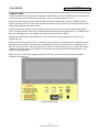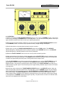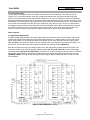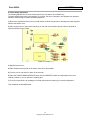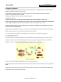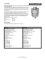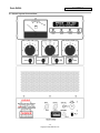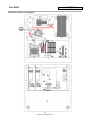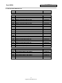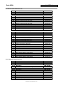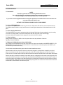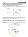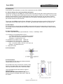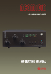
1
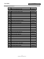
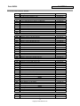
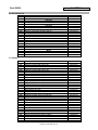
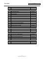
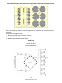
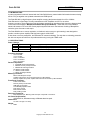
Pride DX-300
CHAPTER 1
1.0 INTRODUCTION:
In putting together this manual I started with the Pride DX300 factory manual added information that was missing
and in error, put together new updated schematics and PCB layouts.
The Pride DX-300 is a high frequency linear amplifier covering the Amateur bands from 3.5 to 30 MHz.
Pride Electronics in San Diego CA was a manufacturer of RF amplifiers and VFO's, as well as
frequency counters. The products that Pride built where assembled by handicap people hence the slogan printed
on the back of the amplifier “Manufactured with Pride by the Handicap”. I think that most of the DX300’s
where built between 1977 and 1978. Some people say that Pride was in the business of selling CB amplifiers
under the guise of amateur radio amps.
The Pride DX300 has no screen regulation, no feedback, and no screen or grid metering it was designed to
provide a medium power amplifier with high power gain at LOW COST.
It does have a receiver preamplifier, and automatic RF actuated switching. The amp has no mistuning protection
but with care anyone should have not problems with tuning it using the TUNE mode.
1.1 SPECIFICATIONS:
Power Ratings:
Mode Drive
SSB
15 watts peak.
CW
10-12 watts.
AM
4-6 watts.
Power
1000 watts PEP input 650 watts nominal peak output any band.
750 watts input, 50% duty cycle, 500 watts nominal output any band
500 watts input, 5-minute cycle, 300 watts nominal output any band.
Frequency Coverage:
3.5 to 4.0 MHz
7.0 to 7.3 MHz
14.0 to 14.35 MHz
21.0 to 21.45 MHz
28.0 to 29.70 MHz
Device Complement:
1 4CX250B ceramic/metal tetrode
1 2N2905 receiver preamp transistor
1 2N2905 RF switching transistor
24 1N4007 rectifier diodes
5 1N4001 rectifier diodes
3 1N914 small signal diodes
Metering Functions:
Meter reads RF power output.
Amplifier tube screen current is monitored by an LED indicator.
Receive amplifier and power amplifier status are also monitored by LED indicators.
Front Panel Functions:
Power On/Off switch
Receive preamp on/off switch
SSB delay on/off switch
Tune/Standby/Operate switch
Plate tuning control
Band selector switch
Plate Loading control
Rear panel Functions:
Bias adjustment pot, Metering Jack and Input / Output RF connections.
AC Power Requirements:
120VAC 60 Hz, 500watts average 1000watts absolute peak.
Dimensions:
12" wide x 9" high x 12" deep.
Weight:
29lbs.
32
Copyright © 2004 CBTricks.com
Pride DX-300
CHAPTER 2
2.0 INSTALLATION:
1) Select a location for your amplifier. RF amplifiers need ventilation, so choose a location that will not restrict the
air flow around the amp and where it won’t get water, coffee, or soft drinks spilled on or in it.
2) Connect a short length of coaxial cable from the exciter to the amplifier input connector. RG58/U or RG8/U
may be used and a PL 259 connector is required at the amplifier end of the cable. This cable should be as short
as is practical, preferable less than five feet.
3) Connect antenna or suitable high power dummy load to the output connector of the amplifier using RG8/U
coax. The smaller RG58/U coax may be used with matched antenna systems (better than 1.5 to 1 SWR) but will
have somewhat higher loss. The amplifier will match most loads from 25 to 100ohm.
4) Exciter power levels above 12 watts PEP or 5 watts carrier level should be avoided as over drive of the
amplifier will occur.
5) The unit should be grounded for R.F. by attaching a ground strap of coaxial shield or 10-12 gauge wire to the
ground post on the amplifier. This should be connected by a short run to a ground rod or cold water pipe. The
idea is to have a short direct earth ground to keep the chassis at radio frequency ground. In many cases normal
operation can be had without such a ground, but a good ground can help prevent television interference, and
make tuning straightforward.
6) The A.C. line cord should be plugged into a three-wire outlet. The electrical circuit should be capable of
handling a 10-ampere load.
Figure 2-0 Rear Panel
32
Copyright © 2004 CBTricks.com
Pride DX-300
CHAPTER 2
Figure 2-1 Front Panel
2.1 OPERATION:
1) Check to see that the TUNE/STANDBY/OPERATE switch is in the center or STANDBY position. Apply power
to the unit by switching the POWER switch to the ON position. You will hear the cooling blower come up to
speed. Wait 60 seconds for the tube to come up to operating temperature.
2) During the time that the amplifier is warming up or at any time that the TUNE/STANDBY/OPERATE switch is
in the STANDBY position, the exciter may be operated normally "straight through" the amplifier.
3) Set the band switch to the same band as that the exciter is tuned to.
4) After warm up, place the TUNE/STANDBY/OPERATE switch into the TUNE position. The OPERATE
indicator will light up, indicating that the unit is ready for operation. If the RECEIVE switch is on, the RECEIVE
indicator will light also, indicating operation of the receive preamplifier.
5) Rotate the PLATE LOADING control to the nine o'clock (counter clockwise) position.
6) Apply several watts of drive from the exciter and quickly peak the PLATE TUNE control for maximum output
as indicated on the front panel wattmeter. The SCREEN overload indicator may glow at this time, and will peak
in brilliance at approximately the same place of tuning that maximum output occurs.
7) The PLATE LOADING control is then turned clockwise 1/2 division or so, and the PLATE TUNING control is
peaked again for maximum output. The brilliance of the SCREEN indicator will peak again, but not quite as
brightly as before. This process is continued until a further increase in the PLATE LOADING control will give no
further increase in power output. This will normally result in approximately 100watts output for three to four watts
of driving power.
8) Un-key the exciter, and place the TUNE/STANDBY/OPERATE switch in the OPERATE position. When the
exciter is keyed again, the power output will be somewhat higher, and the SCREEN indicator may glow brightly
again. Repeat the procedure as before, tuning the PLATE LOADING and PLATE TUNING controls alternately
for maximum output. The PLATE TUNING control should always be the last control that is adjusted. Power
output should be about 250watts for five watts drive at this point in the tune up procedure. When proper loading
is accomplished, the SCREEN indicator should glow only dimly. The plate current, as read on an external meter,
should be in the neighborhood of 200-250ma.
32
Copyright © 2004 CBTricks.com
Pride DX-300
CHAPTER 2
9) For SSB operation, drive power should now be gradually increased to 10 or 12 watts, and the unit peaked for
maximum output. This can be done using the carrier insertion control on some exciters, or if this is not available,
a steady tone may be applied to the microphone input. When maximum power has been achieved, operation
consists of simply keying the microphone and speaking. The SSB delay switch should be in the on position,
which will give the R.F. actuated relays a time delay, so that they won't chatter during transmission. During the
SSB transmission, power output peaks will occur so rapidly that the output meter will not be able to follow the
signal. If a monitor scope is available, it can be seen that the peak power is considerably better than the 400
watts or so that was obtained during tune up. The SCREEN indicator will flicker with the transmission level, and
will reach full brilliance at high peak power levels. This is a faster indicator of peak drive conditions than is the
power output meter.
10) For CW operation, tune up as in step nine above. Power output will be nominal 250 watts for 5 watts of
driving power. The SSB delay switch may be left in the on position to prevent relay chatter during keying.
11) The 4CX-250B transmitting tube has been proven is commercial and military uses where long life and
reliability are major factors. Although it is designed to work a little harder in amateur service, it will still be
extremely reliable if a few common sense rules are applied.
a) Make sure that the tube always receives a good airflow. Remember that a lot of watts are being packed into
that rather small package, and that the only way to keep it cool is to get air through the tube fins. Do not block
the top of the cabinet, or stack other equipment on the amplifier. Make sure that the rear of the chassis (where
the blower gets its air) is open to cool room air. If the bottom cover of the unit has to be removed for service, see
that it is replaced properly prior to plugging in the unit (for safety also). The bottom chassis must be pressurized
in order to force air through the tube fins.
b) Wait 60 seconds before applying drive to the tube. Allowing the tube to properly warm up will help you get the
longest service from it.
c) After a long period on the air, let the amplifier run in the STANDBY mode for a minute or so before turning off
the power switch. This allows the blower to bring the tube down to a cooler temperature fairly rapidly.
d) Avoid excessive R. F. drive to the amplifier.
e) Use care in tuning most tube failures are the result of operator error, not equipment failure. These transmitting
tubes are used for thousands of hours in commercial service, and similar results should be yours with
reasonable precautions.
32
Copyright © 2004 CBTricks.com
Pride DX300
CHAPTER 3
3.0 Circuit Description:
The DX-300 power amplifier uses a 4CX-250B Tetrode ceramic/metal construction, and utilizes forced aircooling. It is in a grounded cathode, driven grid configuration that provides very high power gain, high peak
power output, and excellent linearity and harmonic suppression. The use of tuned input circuits and broadband
matching transformers permits low drive operation combined with additional rejection of exciter harmonics. Class
AB operation of the tube permits high peak powers with low distortion products and harmonics. The amplifier has
a tune function that restricts the power gain of the amplifier for easy, safe tune-ups. The use of a single tube in
the design avoids the problem of matching tubes and it also simplifies repairs. RF actuated switching eliminates
the need for switching contacts on the exciter, which are not found on some of the lower powered rigs on the
market. An internal receiver preamp provides approximately 10db of gain on the higher frequencies.
Power supplies:
3.1 High Voltage Supply PCB:
The high voltage supply consists of the plate supply transformer located on the top of the chassis, and the two
rectifier filter boards below chassis directly under the plate transformer. A bridge rectifier circuit is used, which
allows good utilization of the transformer. Both circuit boards are the same, with the exception of the jumpers
(JP1 and JP2), which determine whether the filter capacitors are on the high side of the series filter string, or on
the low side. The low side board also contains two 6.8ohm, 2W metering resistors (R24, R25).
Each board contains one half of the bridge rectifier circuit, with appropriate jumpers between the boards. The
filter string consists of six 100µf electrolytic capacitors (C11, C12, C13, C22, C23, C24) in series, with voltage
equalizing resistors (R9, R10, R21, R22, R23) across each one. The time constant of the filter when no current is
being drawn is approximately 20 seconds, so that supply will be largely discharged 60 seconds after turn off
(ALWAYS CHECK). The high voltage developed by the supply is approximately 2200 VDC no load, and 1800
VDC at 500mA.
Figure 3-1 High Voltage Power Supply
32
Copyright © 2004 CBTricks.com
Pride DX300
CHAPTER 3
3.2 Screen and Bias Supplies PCB:
The screen and bias supply is also bridge rectified, but with a center tapped transformer and filter string that
allows a split output voltage. Approximately 700 VDC is developed across the two 40µf filter caps (C33, C34),
but due to the circuit configuration this shows up as +350 and -350 VDC. The +350 VDC is fed through a 30ohm
metering resistor (R36) to the screen current. The -350VDC is fed through two power resistors to provide source
current for an 82 volt Zener diode (D25) that provides a stable bias supply voltage.
This -82 volt supply is dropped in a voltage divider consisting of the back panel bias pot and two 3300ohm, 2W
resistors (R40, R41) to provide an adjustable, stable bias source for the tube control grid.
Figure 3-2 Screen and Bias Voltage Power Supply
3.3 Low Voltage Supply PCB:
This supply consists of a full wave voltage doubler, which is supplied from the 6.3volt filament winding on the
smaller transformer. 12 to 15 VDC is developed for use of the receive preamp, relays and indicators.
Figure 3-3 Low Voltage Power Supply
32
Copyright © 2004 CBTricks.com
Pride DX300
CHAPTER 3
3.4 R.F. Input and Control Board:
This board is located under chassis near the tube socket, and is mounted horizontally. It contains the R.F.
switching circuitry, input matching transformer and tuned toroid input coils, the receiver preamp, and some of the
control circuitry.
Control
Drive power from the exciter is fed to one set of contacts on the (RL1) 4PDT relay and coupled also to a 2N2905
(Q1) relay-switching transistor. When the amplifier is in the standby mode, drive is fed through the relay to the
output connector. In the operate or tune mode, drive is switched to the 9:1 input matching transformer (T3),
which steps the impedance up from 50ohm to 450ohm to feed the input circuitry. The rear deck of the Band
Switch selects a tuned circuit for the appropriate band. Two 1500ohm, 2W resistors (R44, R45) are in parallel
with the resonant input circuit to provide proper loading and bandwidth. Adjustable bias voltage is fed to the grid
through a 200uH choke (L14), an input toroid, and the parasitic choke (Z1) on the tube grid connection.
Figure 3-4 RF Input Circuit
32
Copyright © 2004 CBTricks.com
CHAPTER 3
Pride DX300
Another set of contacts on the (RL1) 4PDT relay switches the cathode circuit of the tube to ground when the
amplifier goes into the "on the air" condition. When not transmitting, two 18K, 2W resistors (R46, R47) provide a
cathode blocking bias that prevents the tube from pulling current. The two 270ohm, 2W resistors (R48, R49) that
are in series with the cathode line provide some additional bias during the TUNE mode, causing a loss in power
gain and making it easy to tune up at lower power. These resistors are shorted out by a section of the
TUNE/STANDBY/OPERATE switch when in the OPERATE mode.
Figure 3-41 Cathode Circuit
The (RL2) DPDT relay on the main R.F. board is used solely for switching the receiver preamp in and out of the
antenna circuit. It is controlled by both the RECEIVE switch on the front panel and the grounding contact on the
(RL1) 4PDT relay.
Figure 3-42 Receiver Preamp Circuit
32
Copyright © 2004 CBTricks.com
Pride DX300
CHAPTER 3
3.5 Safety Interlock PCB
Figure 3-5 Safety Interlock Circuit
Never turn on the amp with cover off:
The shorting safety switch will cause the high voltage to short out.
If this happens it will usually takes out R59 or the bridge rectifier.
3.6 Wattmeter PCB:
Figure 3-6 Wattmeter Circuit
32
Copyright © 2004 CBTricks.com
Pride DX300
CHAPTER 4
Maintenance
The following information is presented so that the competent service technician should have no trouble in
performing routine service on the Pride DX-300.
Lethally high voltages are present inside the amplifier unit. Never remove either top or bottom cover when power
line is connected. DO NOT attempt to operate unit when covers are removed:
1) Lethal voltages would be open to contact.
2) Protective interlock on top cover will short circuit the high voltage power supply; attempting to operate under
these conditions can cause damage to power supply, amplifier tube, or both.
3) Attempting to operate the unit with bottom cover removed causes loss of air pressure to the tube, and can
cause rapid failure of the tube.
4) Attempting to operate the unit with top cover removed (with the interlock blocked) may make the amplifier
erratic in tuning and performance due to the high level of R.F. on the top chassis coupling to the coaxial input
cable at the rear of the chassis. If repairs should be necessary, contact the factory, or a repair facility with proper
equipment and technical experience for the servicing of high power amplifiers.
If covers need be removed, allow two minutes after turning the unit off and unplugging the line cord before
removing covers.
4.0 Plate current measurement:
Plate current can be monitored by means of an external meter plugged into the METERING jack on the back
panel. The voltmeter should be connected as below:
Figure 4-0 Meter Connection
The following chart converts voltage as read at the metering jack to actual plate current.
.17V = 50mA
.34V = 100mA
.51V = 150mA
.68V = 200mA
.85V = 250mA
1.02V = 300mA
1.19V = 350mA
1.36V = 400mA
1.53V = 450mA
1.70V = 500mA
32
Copyright © 2004 CBTricks.com
Pride DX300
CHAPTER 4
4.1 Bias voltage adjustment:
The following adjustment is from the factory manual you may want to do it another way.
The bias voltage should rarely need attention. If, however, the tube is changed or the adjustment is otherwise
disturbed, the following procedure should be adhered to.
1) Be sure the amplifier has been off for several minutes to allow enough time to discharge the power supplies.
Remove the bottom cover.
2) Place a jumper wire or clip lead from point (A) on the main circuit board to ground. Refer to pictorial for
specific placement of the jumper.
Figure 4-1 Jumper A
3) Replace bottom cover.
4) Place a 50ohm dummy load on the output connector of the amplifier.
5) Turn the unit on and allow it to warm for 60 seconds.
6) Place the TUNE/STANDBY/OPERATE switch into the OPERATE position and adjust bias control for a
reading of 35mA or .12V as read at the metering jack.
7) Turn off unit and allow it to discharge for several minutes before restoring it to normal configuration.
This completes the bias adjustment.
32
Copyright © 2004 CBTricks.com
Pride DX300
CHAPTER 4
4.2 Wattmeter Calibration:
The following adjustment is from the factory manual you may want to do it bypassing the safety interlock and
adjust it with the top removed but use caution.
If adjustment becomes necessary, it should be performed only if the following equipment is available:
Exciter: 100 to 200watts output at 28 MHz
Dummy load: 50ohm with an accurately calibrated wattmeter.
Calibration procedure:
1) Remove the top cover after allowing several minutes for the unit to discharge to a safe level.
2) Disconnect the right hand (as viewed from the front of the unit) coax cable at the wattmeter board and attach
a short length of RG58/U coax cable from the wattmeter board to the output of your exciter.
3) Disconnect the left hand coax cable and attach a short length of RG58/U from the wattmeter board to the
input of the dummy load/wattmeter.
4) Apply power and adjust the exciter for an output of 100 to 200watts as read on the dummy load/wattmeter.
5) Set the potentiometer on the wattmeter board for the same reading.
This now completes the calibration of the wattmeter. Restore the unit to its original configuration.
4.3 Input SWR adjustment:
If the input SWR should require adjustment on any particular band, the following procedure should be used:
1) Remove the bottom cover after allowing sufficient time for the power supply to discharge to a safe level.
2) Apply +12 VDC to point (B) as identified on the pictorial of the main circuit board.
Figure 4-3 Jumper B
3) Place the TUNE/STANDBY/OPERATE switch into the operate position.
4) Apply approximately three watts of drive to the input of the amplifier (with band switch set to the appropriate
band).
5) Spread or compress the turns of the toroid for the band in use to obtain the lowest SWR reading possible.
6) Restore the unit to its original configuration.
32
Copyright © 2004 CBTricks.com
Pride DX300
CHAPTER 4
4.4 Voltage Checks
As the voltages present on the DX-300 chassis are potentially lethal, the procedure below must be followed
when checking voltages.
1) Make sure that the unit is unplugged and has been off for several minutes to allow all voltages to bleed to zero.
2) Remove the top cover. Doing so will engage the safety interlock so never apply A.C. power when this cover is
removed.
3) Loosen and remove the anode clamp from the 4CX-250B tube (V1). Remove the tube, the ceramic chimney,
and the anode clamp from the chassis.
Make sure the parasitic suppressor (Z2) is suspended away from any chassis parts.
4) Replace the top cover on the amplifier.
5) Lay the amplifier on its side or top and remove the bottom cover.
Remember the tube must be removed or it will be damaged by the loss of cooling air when the unit is powered
without the bottom cover.
6) Apply A.C. power to the unit. WARNING: Extreme caution must be used when working with voltages of this
level. Always be cautious and alert while working on the live chassis.
7) Refer to the individual circuit board pictorials for voltage readings and locations. Voltages on the tube socket
are as follows:
Pin 1
Pins 3 and 7
Grid Connection
+350 VDC, ± 10%
6.3VAC, ± 10%
-82 to -64 VDC, depending on the setting of bias control and mods installed.
Caution: When measuring the B+ supply (+2200 VDC), use only a meter, which is designed to measure 2kv
plus safety during operation at high voltage levels.
8) Restore the unit to its original condition.
4.5 Preventive Maintenance
There are four circuit boards in the bottom compartment have all the wires attached to them with small springmetal socket contacts. Pull each of the socket contacts one at a time. If any of them that feel loose when you pull
on it should be GENTLY squeezed with a small pair of pliers so that it has some friction when you push it back
onto its circuit-board pin. Check for burnt components on each of the circuit boards replace as needed and look
for reason for failure.
Important
When you put the bottom cover back on check the seal and be sure that you put all the screws in.
Also be sure that the 3 screws on the back of the top cover are installed.
Now take a close look at that big copper hair-pin (Z2) that attaches to the tube clamp topside. If the resistors look
like toast, new resistors should be installed before you try to run it.
If the resistors look okay, and it has all 3 of them, leave it alone. If you replace them, we recommend using a 5Watt rated 100-ohm carbon-film or metal-film resistor. They will withstand more abuse than the original 2 Wattrated parts. DO NOT use wire wound resistors. Period. Both Mouser Electronics and Westgate Labs sell this
resistor.
Check the main fuse (F1) in the back, and check the rating printed on it. The correct size is 10 Amp, 125 Volt or
250 Volt. A 32-Volt fuse is NOT the right type for this amplifier.
32
Copyright © 2004 CBTricks.com
Pride DX300
CHAPTER 4
4.6 Tube Replacement:
If a tube failure does occur, a likely reason for this would be a loss of one or more
of the required operating voltages at the tube socket. Thus, before a tube is
replaced, the voltage measurement procedure should be followed to determine if
further repairs are necessary. If all required voltages are present, the tube can then
be replaced safely.
The 4CX250R is a 'ruggedized' 4CX250B with a better cathode and more gain. It is
pin and heater compatible with the 250B. The Eimac catalogue says: "The
4CX250R/7580W will replace the 4CX250B in equipment where the range of bias
adjustment will tolerate this higher perveance tube and where the tuning range can
compensate for the small differences in input and output capacitances. It means
you may need a bit more negative G1 bias to set the required standing current
(100mA per tube).
Brand of tube types that work in the DX300
Eimac
Best
Taylor
Very Good
Svetlanta (Russian)
Very Good
Edcom
Not Good
Tubes that will work
4CX250B, 4CX250R,
Have heard of people using a 4CX350B but I haven’t tested that.
4CX250B/7203
4CX250R/7580W
Characteristics
Plate Dissipation (Max.) 250 Watts
Screen Dissipation (Max.) 12 Watts
Grid Dissipation (Max.) 2 Watts
Frequency for Max. rating (CW) 500 MHz
Amplification Factor 5
Filament/Cathode Oxide Coated
Voltage 6.0 Volts
Current 2.6 Amps
Capacitance Grounded Cathode
Input 4.8 pf
Output .04 pf
Feedthrough 17.5 pf
Capacitance Grounded Grid
Input --- pf
Output --- pf
Feedthrough --- pf
Cooling Forced Air
Base 9 Pin Special
Air Socket SK-600A
Air Chimney SK-606
Boiler --Length 2.46 in; 62.50 mm
Diameter 1.64 in; 41.70 mm
Weight 4 oz; 113 gm
Characteristics
Plate Dissipation (Max.) 250 Watts
Screen Dissipation (Max.) 12 Watts
Grid Dissipation (Max.) 2 Watts
Frequency for Max. rating (CW) 500 MHz
Amplification Factor 5
Filament/Cathode Oxide Coated
Voltage 6.0 Volts
Current 2.6 Amps
Capacitance Grounded Cathode
Input 4.5 pf
Output .04 pf
Feedthrough 15.7 pf
Capacitance Grounded Grid
Input 4.5 pf
Output .01 pf
Feedthrough 13.0 pf
Cooling Forced Air
Base 9 Pin Special
Air Socket SK-600A
Air Chimney SK-606
Boiler --Length 2.46 in; 62.50 mm
Diameter 1.64 in; 41.70 mm
Weight 4 oz; 113 gm
32
Copyright © 2004 CBTricks.com
Pride DX300
CHAPTER 5
5.0 Low Voltage Supply PCB:
32
Copyright © 2004 CBTricks.com
Pride DX300
CHAPTER 5
5.1 High Voltage Supply PCB (Board #1):
32
Copyright © 2004 CBTricks.com
Pride DX300
CHAPTER 5
5.2 High Voltage Supply PCB (Board #2):
32
Copyright © 2004 CBTricks.com
Pride DX300
CHAPTER 5
5.3 Wattmeter PCB:
32
Copyright © 2004 CBTricks.com
Pride DX300
CHAPTER 5
5.4 RF Input and Control PCB:
32
Copyright © 2004 CBTricks.com
Pride DX300
CHAPTER 5
5.5 Safety Interlock PCB:
32
Copyright © 2004 CBTricks.com
Pride DX300
CHAPTER 5
5.6 PCB Trace Layouts:
32
Copyright © 2004 CBTricks.com
Pride DX300
CHAPTER 5
PCB Trace Layouts (Cont.):
32
Copyright © 2004 CBTricks.com
Pride DX300
CHAPTER 5
5.7 Chassis Layouts Front and Rear:
32
Copyright © 2004 CBTricks.com
Pride DX300
CHAPTER 5
5.8 Chassis Layouts Top and Bottom:
32
Copyright © 2004 CBTricks.com
Pride DX300
CHAPTER 6
6.1 HIGH VOLTAGE PWR SUPPLY #1:
Ref. #
Ref. #
R13
R14
R15
R16
R17
R18
R19
R20
R21
R22
R23
R24
R25
R26
Ref. #
C14
C15
C16
C17
C18
C19
C20
C21
C22
C23
C24
Ref. #
D9
D10
D11
D12
D13
D14
D15
D16
Description
ASSY DX-300 HIGH VOLTAGE PWR SUPPLY #1
PCB DX-300 HIGH VOLTAGE PWR SUPPLY
Resistors
Description
Resistor, Carbon Film 470K Ohm 1/2W
Resistor, Carbon Film 470K Ohm 1/2W
Resistor, Carbon Film 470K Ohm 1/2W
Resistor, Carbon Film 470K Ohm 1/2W
Resistor, Carbon Film 470K Ohm 1/2W
Resistor, Carbon Film 470K Ohm 1/2W
Resistor, Carbon Film 470K Ohm 1/2W
Resistor, Carbon Film 470K Ohm 1/2W
Resistor, Carbon Film 150K Ohm 2W 10%
Resistor, Carbon Film 150K Ohm 2W 10%
Resistor, Carbon Film 150K Ohm 2W 10%
Resistor, Carbon Film 6.8 Ohm 2W 5%
Resistor, Carbon Film 6.8 Ohm 2W 5%
Resistor, Wire wound 25 Ohm 10W 10%
Capacitors
Description
Capacitor, Ceramic Disk 0.001µF 1KV
Capacitor, Ceramic Disk 0.001µF 1KV
Capacitor, Ceramic Disk 0.001µF 1KV
Capacitor, Ceramic Disk 0.001µF 1KV
Capacitor, Ceramic Disk 0.001µF 1KV
Capacitor, Ceramic Disk 0.001µF 1KV
Capacitor, Ceramic Disk 0.001µF 1KV
Capacitor, Ceramic Disk 0.001µF 1KV
Capacitor, Electrolytic 100µF 450V
Capacitor, Electrolytic 100µF 450V
Capacitor, Electrolytic 100µF 450V
Diodes
Description
Diode, Rectifier 1N4007 1 AMP 1000PIV
Diode, Rectifier 1N4007 1 AMP 1000PIV
Diode, Rectifier 1N4007 1 AMP 1000PIV
Diode, Rectifier 1N4007 1 AMP 1000PIV
Diode, Rectifier 1N4007 1 AMP 1000PIV
Diode, Rectifier 1N4007 1 AMP 1000PIV
Diode, Rectifier 1N4007 1 AMP 1000PIV
Diode, Rectifier 1N4007 1 AMP 1000PIV
32
Copyright © 2004 CBTricks.com
MFR. Part No.
01-0300-01
82-0300-01
MFR. Part No.
06-4704-00
06-4704-00
06-4704-00
06-4704-00
06-4704-00
06-4704-00
06-4704-00
06-4704-00
06-1504-02
06-1504-02
06-1504-02
06-0680-02
06-0680-02
17-2500-10
MFR. Part No.
08-0102-00
08-0102-00
08-0102-00
08-0102-00
08-0102-00
08-0102-00
08-0102-00
08-0102-00
23-0107-45
23-0107-45
23-0107-45
MFR. Part No.
48-4007-00
48-4007-00
48-4007-00
48-4007-00
48-4007-00
48-4007-00
48-4007-00
48-4007-00
Pride DX300
CHAPTER 6
6.2 HIGH VOLTAGE PWR SUPPLY #2:
Ref. #
Ref. #
R1
R2
R3
R4
R5
R6
R7
R8
R9
R10
R11
R12
Ref. #
C3
C4
C5
C6
C7
C8
C9
C10
C11
C12
C13
Ref. #
D1
D2
D3
D4
D5
D6
D7
D8
Description
ASSY.HIGH VOLTAGE PWR SUPPLY #2
HIGH VOLTAGE PWR SUPPLY PCB
Resistors
Description
Resistor, Carbon Film 470K Ohm 1/2W
Resistor, Carbon Film 470K Ohm 1/2W
Resistor, Carbon Film 470K Ohm 1/2W
Resistor, Carbon Film 470K Ohm 1/2W
Resistor, Carbon Film 470K Ohm 1/2W
Resistor, Carbon Film 470K Ohm 1/2W
Resistor, Carbon Film 470K Ohm 1/2W
Resistor, Carbon Film 470K Ohm 1/2W
Resistor, Carbon Film 150K Ohm 2W 10%
Resistor, Carbon Film 150K Ohm 2W 10%
Resistor, Carbon Film 150K Ohm 2W 10%
Resistor, Wire wound 25 Ohm 10W 10%
Capacitors
Description
Capacitor, Ceramic Disk 0.001µF 1KV
Capacitor, Ceramic Disk 0.001µF 1KV
Capacitor, Ceramic Disk 0.001µF 1KV
Capacitor, Ceramic Disk 0.001µF 1KV
Capacitor, Ceramic Disk 0.001µF 1KV
Capacitor, Ceramic Disk 0.001µF 1KV
Capacitor, Ceramic Disk 0.001µF 1KV
Capacitor, Ceramic Disk 0.001µF 1KV
Capacitor, Electrolytic 100µF 450V
Capacitor, Electrolytic 100µF 450V
Capacitor, Electrolytic 100µF 450V
Diodes
Description
Diode, Rectifier 1N4007 1 AMP 1000PIV
Diode, Rectifier 1N4007 1 AMP 1000PIV
Diode, Rectifier 1N4007 1 AMP 1000PIV
Diode, Rectifier 1N4007 1 AMP 1000PIV
Diode, Rectifier 1N4007 1 AMP 1000PIV
Diode, Rectifier 1N4007 1 AMP 1000PIV
Diode, Rectifier 1N4007 1 AMP 1000PIV
Diode, Rectifier 1N4007 1 AMP 1000PIV
MFR. Part No.
01-0300-00
82-0300-01
MFR. Part No.
06-4704-00
06-4704-00
06-4704-00
06-4704-00
06-4704-00
06-4704-00
06-4704-00
06-4704-00
06-1504-02
06-1504-02
06-1504-02
17-2500-10
MFR. Part No.
08-0102-00
08-0102-00
08-0102-00
08-0102-00
08-0102-00
08-0102-00
08-0102-00
08-0102-00
23-0107-45
23-0107-45
23-0107-45
MFR. Part No.
48-4007-00
48-4007-00
48-4007-00
48-4007-00
48-4007-00
48-4007-00
48-4007-00
48-4007-00
6.3 B+ CIRCUITRY (Safety Interlock):
Ref. #
Ref. #
L8
Ref. #
R59
Ref. #
C56
Ref. #
Description
ASSY. B+ CIRCUITRY (Safety Interlock)
PCB, B+ CIRCUITRY
Inductors
Description
ASSY. Toriod Inductor 10µH 10 Windings
Resistors
Description
Resistor, Carbon Film 150K Ohm 2W 10%
Capacitors
Description
Capacitor, Ceramic Disk 0.005µF 3KV
MFR. Part No.
01-0300-16
82-0300-04
Description
Ground Strap, Safety Interlock
Bracket, B+ Circuitry
MFR. Part No.
85-0300-15
85-0300-18
32
Copyright © 2004 CBTricks.com
MFR. Part No.
01-0300-28
MFR. Part No.
06-1504-02
MFR. Part No.
08-0502-00
Pride DX300
CHAPTER 6
6.4 LOW VOLTAGE PWR SUPPLY:
Ref. #
Ref. #
R27
R28
R29
R30
R31
R32
R33
R34
R35
R36
R37
R38
R39
R40
R41
R42
Ref. #
C25
C26
C27
C28
C29
C30
C31
C32
C33
C34
C36
C37
Ref. #
D17
D18
D19
D20
D21
D22
D23
D24
D25
D26
D27
D28
Description
ASSY. LOW VOLTAGE PWR SUPPLY
LOW VOLTAGE PWR SUPPLY PCB
Resistors
Description
Resistor, Carbon Film 470K Ohm 1/2W
Resistor, Carbon Film 470K Ohm 1/2W
Resistor, Carbon Film 470K Ohm 1/2W
Resistor, Carbon Film 470K Ohm 1/2W
Resistor, Carbon Film 470K Ohm 1/2W
Resistor, Carbon Film 470K Ohm 1/2W
Resistor, Carbon Film 470K Ohm 1/2W
Resistor, Carbon Film 470K Ohm 1/2W
Resistor, Carbon Film 150 Ohm 1/2W 10%
Resistor, Carbon 30 Ohm 1/2W 5%
Resistor, Wire wound 20K Ohm 10W
Resistor, Wire wound 12K Ohm 10W 10%
Resistor, Wire wound 10K Ohm 10W 10%
Resistor, Carbon 3.3K Ohm 2W 5%
Resistor, Carbon 3.3K Ohm 2W 5%
Resistor, Carbon Film 680 Ohm 1/2W 5%
Capacitors
Description
Capacitor, Ceramic Disk 0.001µF 1KV
Capacitor, Ceramic Disk 0.001µF 1KV
Capacitor, Ceramic Disk 0.001µF 1KV
Capacitor, Ceramic Disk 0.001µF 1KV
Capacitor, Ceramic Disk 0.001µF 1KV
Capacitor, Ceramic Disk 0.001µF 1KV
Capacitor, Ceramic Disk 0.001µF 1KV
Capacitor, Ceramic Disk 0.001µF 1KV
Capacitor, Electrolytic 40µF 450V
Capacitor, Electrolytic 40µF 450V
Capacitor, Electrolytic 1000µF 25V
Capacitor, Electrolytic 1000µF 25V
Diodes
Description
Diode, Rectifier 1N4007 1 AMP 1000PIV
Diode, Rectifier 1N4007 1 AMP 1000PIV
Diode, Rectifier 1N4007 1 AMP 1000PIV
Diode, Rectifier 1N4007 1 AMP 1000PIV
Diode, Rectifier 1N4007 1 AMP 1000PIV
Diode, Rectifier 1N4007 1 AMP 1000PIV
Diode, Rectifier 1N4007 1 AMP 1000PIV
Diode, Rectifier 1N4007 1 AMP 1000PIV
Diode, Zener 82V 5W 1N5375
Diode, Rectifier 1N4001 1A 600PIV
Diode, Rectifier 1N4001 1A 600PIV
Diode, Rectifier 1N4001 1A 600PIV
32
Copyright © 2004 CBTricks.com
MFR. Part No.
01-0300-02
82-0300-02
MFR. Part No.
06-4704-00
06-4704-00
06-4704-00
06-4704-00
06-4704-00
06-4704-00
06-4704-00
06-4704-00
06-1501-00
06-0301-00
17-2003-10
17-1203-10
17-1003-10
06-3302-02
06-3302-02
06-6801-00
MFR. Part No.
08-0102-00
08-0102-00
08-0102-00
08-0102-00
08-0102-00
08-0102-00
08-0102-00
08-0102-00
23-0406-45
23-0406-45
22-0108-00
22-0108-00
MFR. Part No.
48-4007-00
48-4007-00
48-4007-00
48-4007-00
48-4007-00
48-4007-00
48-4007-00
48-4007-00
48-5375-00
48-4001-00
48-4001-00
48-4001-00
Pride DX300
CHAPTER 6
6.5 RF INPUT AND CONTROL BOARD:
Ref. #
Ref. #
L1
L2
L3
L4
L5
L10
L11
L14
T3
Ref. #
R44
R45
R46
R47
R48
R49
R50
R51
R52
R53
R54
R55
R56
R57
R58
Ref. #
C39
C40
C41
C42
C43
C50
C51
C52
C53
C54
C55
Ref. #
D29
D30
D31
D32
Ref. #
RL1
RL2
Ref. #
Q1
Q2
Description
ASSY. RF INPUT AND CONTROL
RF INPUT AND CONTROL PCB
Inductors
Description
Choke, SUB MIN 200µH NIN Q47 80 METERS
ASSY. Coil Input Toroid 40 METERS
ASSY. Coil Input Toroid 20 METERS
ASSY. Coil Input Toroid 15 METERS
ASSY. Coil Input Toroid 10 METERS
Choke, RF 22 µH
Choke, RF 0.82 µH
Choke, SUB MIN 200µH NIN Q47
ASSY. Input Transformer 3 Wires 10 Windings
Resistors
Description
Resistor, Carbon 1.5K Ohm 2W 10%
Resistor, Carbon 1.5K Ohm 2W 10%
Resistor, Carbon 18K Ohm 2W 10%
Resistor, Carbon 18K Ohm 2W 10%
Resistor, Carbon 270 Ohm 2W 10%
Resistor, Carbon 270 Ohm 2W 10%
Resistor, Carbon Film 1K Ohm 1W
Resistor, Carbon Film 470 Ohm 1/2W 5%
Resistor, Carbon Film 680 Ohm 1/2W 5%
Resistor, Carbon Film 680 Ohm 1/2W 5%
Resistor, Carbon Film, 10K Ohm 1/2W 5%
Resistor, Carbon Film 270 Ohm 1/2W 5%
Resistor, Carbon Film 470 Ohm 1/2W 5%
Resistor, Carbon Film 68K Ohm 1/2W 5%
Resistor, Carbon Film 1K Ohm 1/2W 5%
Capacitors
Description
Capacitor, Ceramic Disk 0.01µF 1KV
Capacitor, Ceramic Disk 0.01µF 1KV
Capacitor, Dipped Mica 39pF 5% DM15
Capacitor, Dipped Mica 10pF 5% DM15
Capacitor, Ceramic Disk 0.01 µF 1KV
Capacitor, Ceramic Disk 0.01µF 50V
Capacitor, Electrolytic 35µF 25V Axial
Capacitor, Ceramic Disk 0.001µF 1KV
Capacitor, Dipped Mica 120pF 5% DM15
Capacitor, Dipped Mica 50pF 5% DM15
Capacitor, Ceramic Disk 0.001µF 1KV
Diodes
Description
Diode, Signal 1N914
Diode, Rectifier 1A 50V Plastic
Diode, Rectifier 1A 50V Plastic
Diode, Signal 1N914
Relays
Description
Relay, 4PDT Allied Control TY154-4C-12DC
Relay, 2PDT Potter & Brumfield R10-E1-Y2-V185
Transistors
Description
Transistor, 2N2905 PNP SI Switching
Transistor, 2N2905 PNP SI Switching
32
Copyright © 2004 CBTricks.com
MFR. Part No.
01-0300-03
82-0300-03
MFR. Part No.
24-2000-00
01-0300-26
01-0300-25
01-0200-24
01-0300-23
24-2200-00
24-0820-00
24-2000-00
01-0300-22
MFR. Part No.
06-1502-02
06-1502-02
06-1803-02
06-1803-02
06-2701-02
06-2701-02
06-1002-01
06-4701-00
06-6801-00
06-6801-00
06-1003-00
06-2701-00
06-4701-00
06-6803-00
06-1002-00
MFR. Part No.
08-0103-02
08-0103-02
21-1390-00
21-1100-00
08-0103-02
05-0103-00
22-0356-00
08-0102-00
21-1121-00
21-1500-00
08-0102-00
MFR. Part No.
48-0914-00
48-4001-00
48-4001-00
48-0914-00
MFR. Part No.
41-1024-00
41-1022-01
MFR. Part No.
48-2905-00
48-2905-00
Pride DX300
CHAPTER 6
6.6 WATTMETER PCB:
Ref. #
Description
ASSY. WATTMETER PCB
WATTMETER PCB
MFR. Part No.
01-0300-09
82-0300-06
Inductors
Ref. #
T4
Ref. #
RV2
R60
R61
Ref. #
C57
C58
C59
C60
Ref. #
D33
Ref. #
M1
Description
ASSY. Toroid Coil 17 Winding
MFR. Part No.
01-0300-27
Resistors
Description
Potentiometer, Trimpot 50K Ohm 1/4 W
Resistor, Carbon Film 15K Ohm 1/2W 5%
Resistor, Carbon Film 68 Ohm 2W 5%
Capacitors
Description
4-60pF
Capacitor, Dipped Mica 330pF 5% DM-15
Capacitor, Ceramic Disk 0.001µF 1KV
Capacitor, Ceramic 0.1µF 100V
Diodes
Description
Diode, Signal 1N914
Meters
Description
Meter, 1ma F.S. With Special Scale
MFR. Part No.
19-5003-00
06-1503-00
06-6800-02
MFR. Part No.
21-1331-00
08-0102-00
08-0104-02
MFR. Part No.
48-0914-00
MFR. Part No.
49-0300-00
6.7 CHASSIS
Ref. #
C1
C2
C35
C44
C45
C46
C47
C48
C49
C62
C63
C64
C65
C66
C67
C68
C69
C70
Ref. #
S1
S2
S3
S4
S5
S6
Description
Capacitor, Ceramic Disk 0.01µF 1KV
Capacitor, Ceramic Disk 0.01µF 1KV
Capacitor, Ceramic Disk 0.001µF 1KV (Across LED4)
Capacitor, Ceramic Disk 0.01µF 1KV
Capacitor, Ceramic Disk 0.01µF 1KV
Capacitor, Ceramic Disk 0.01µF 1KV
Capacitor, Ceramic Disk 0.01µF 1KV
Capacitor, Ceramic Disk 0.01µF 1KV
Capacitor, Ceramic Disk 0.01µF 1KV
Capacitor, Ceramic Disk 0.01µF 1KV
Capacitor, Dipped Mica 360pF 1KV
Capacitor, Dipped Mica 360pF 1KV
ASSY. CAPACITOR 165pF TEFLON DIELECTRIC
Teflon Sheet 4.50 X 3.50
Teflon Plug 1.0 DIA
Brass Sheet 4.00 X 3.00
Teflon Sheet 2.00 X 2.00
Brass Sheet 1.40 X 1.40
Capacitor, Variable, Panel 10-110pF 3KV
Capacitor, Variable, Panel 1350pF 750V (450pF x 3)
Capacitor, Ceramic Disk 0.0022µF 7.5KV
Capacitor, Ceramic Disk 0.001µF 1KV (Across LED3)
Capacitor, Ceramic Disk 0.01µF 1KV
MFR. Part No.
08-0103-02
08-0103-02
08-0102-00
08-0103-02
08-0103-02
08-0103-02
08-0103-02
08-0103-02
08-0103-02
08-0103-02
21-1361-01
21-1361-01
01-0300-13
85-0300-04
85-0300-05
85-0300-06
85-0300-07
85-0300-08
20-1101-03
20-2450-00
08-0222-07
08-0102-00
08-0103-02
Description
Switch, SPST, l0A
Switch, 3A SPST
Switch, 3A SPST
Switch, DPDT, Center Off 10A
Switch, Band Ceramic 2 Wafer 5 Position
Coupler, Shaft
Switch, Phonetic 1 Pole 5 Position
MFR. Part No.
40-8006-00
40-1606-00
40-1606-00
40-8706-00
40-9002-00
26-0138-00
40-3000-00
32
Copyright © 2004 CBTricks.com
Pride DX300
CHASSIS (Cont.)
Ref. #
L7
L12
CHAPTER 6
Description
ASSY. Tank Coil 15-80 Meters
Choke, RF 1mH 160 MA
Capacitor Strap
MFR. Part No.
01-0300-15
24-1006-00
85-0300-17
Description
Dial, Figure Black DX-300
Knob, Black DX-300
Knob, Black DX-300
CAP. Knob DX-300
L.E.D. Red Diffused
L.E.D. Red Diffused
L.E.D. Red Diffused
L.E.D. Red Diffused
Clip & Ring, LED Panel Mounting
Parasitic Suppressor, Grid 4Turns #22
Resistor, Carbon Film 150 Ohm 1/2W (R65)
ASSY. Parasitic Suppressor
Resistor, Carbon Film 100 Ohm 2W (R62)
Resistor, Carbon Film 100 Ohm 2W (R63)
Resistor, Carbon Film 100 Ohm 2W (R64)
Choke, RF Plate 55µH
Transformer, DX-300 High Voltage
Transformer, DX-300 Low Voltage
Blower, High Output Modified
Flange, Outlet For Blower PN 87-1250-00
MFR. Part No.
32-0299-00
32-2912-00
32-2912-01
42-0290-00
49-5024-00
49-5024-00
49-5024-00
49-5024-00
05-5024-00
01-0300-07
Description
Tube, 4CX250B
Socket, Electron Tube E.F. Johnson 124-110
Screen bypass Cap, Round Frame E.F. Johnson 124-113-001
Socket Chimney, E.F. Johnson 124-0111-011
MFR. Part No.
65-0250-00
09-0250-00
Ref. #
PL-1
PL-2
PL-3
PL-4
RV1
F1
Description
Line Cord. 3 Wire 1118W Molded Plug
SO239 (RF Input)
SO239 (RF Output)
Recept 3-COND Round (Metering Jack)
POT. 500 Ohm 2.25W 10% SCR. ADJ. .625 SHFT
Fuse, AGC 10 AMP
Fuse Extractor Post
MFR. Part No.
28-3186-00
Ref. #
Description
Foot, Rubber 31/32"
Cover
Bottom Plate
MFR. Part No.
75-2135-00
85-0300-11
85-0300-14
Ref. #
LED1
LED2
LED3
LED4
Z1
Z2
L9
T1
T2
BL1
Ref. #
V1
32
Copyright © 2004 CBTricks.com
01-0300-05
24-0014-00
25-0300-01
25-0300-02
87-1250-00
87-1250-01
09-0250-01
09-7135-00
18-5001-02
65-0010-00
67-1200-00
Pride DX300
CHAPTER 7
Circuit Modifications
7.0 Introduction
NOTE:
Exercise a great deal of care with any Modifications done
Due to the high Voltage, and close proximity of the surrounding components.
If done wrong you could destroy components / or KILL yourself.
If you have even the slightest doubts or the proper equipment, it would be wise to have someone else
you trust perform the mod for you.
SO TAKE YOUR TIME AND DOUBLE CHECK YOUR WORK!!!!
7.1 Screen LED Modification
The 'Screen' LED (LED4) seldom lasts long, but we use a 2W part for R35 and R36, same resistance values.
The LED will still die if there's a surge on the screen, but the larger resistors take it better than the stock 1/2W
parts.
7.2 Screen Supply Modification
The Pride DX300 has no screen regulation and should, Nomad Radio (http://www.nomadradio.com) is working
on a new Low Voltage PCB. I have seen Prides with a 25K 10W to ground on the +350v supply.
A person could build a regulator for the supply. So check his web site for details.
7.3 Tube Oscillation
Adding another capacitor on the B+ side of the plate choke can stop oscillation of the tube.
Typically .001µF at 3000Volts
7.4 Wattmeter PCB Modification (Nomad Radio Mod)
On the small circuit board bolted to the rear of the meter, the output coax should be SOLDERED DIRECTLY TO
THE BOARD. First unplug the two coax cables from it. Loosen the nuts on the meter posts, and GENTLY pull
the board away from the meter body.
You will need to unsolder the bare ground wire from the inboard-lower corner.
Heat the solder to the four pins where the two coaxes were plugged in, and pull them completely out of their
holes. You will need to ream the two ground holes (the ones on the outside edge) out to a hole size of about
3/32 of an inch. You also need to clear any leftover solder from the two holes where the coax center wires attach.
Remove the spring contacts from both the coax cables that you unplugged from the meter board. Strip about 3/8
of an inch from the end of each. You should also pull off the shrink tubing that covers the coax braid. Tin each of
these wire ends to hold all those loose strands together. Now insert the tinned wire ends back into the four holes
in the meter board. Solder them in place, and that skinny bare ground wire on the corner of the board. When the
meter board is mounted back onto the meter posts.
32
Copyright © 2004 CBTricks.com
Pride DX300
CHAPTER 7
7.5 Bias Circuit Modification Version1 (Nomad Radio Mod)
The Bias voltage is a Negative 82 Volt supply which is set between -65 and -68 volts to the tube.
The most common part failure is the bias pot (RV1) 500ohm 2W linear pot and an 82-Volt 5-Watt zener (D25).
One substitute for the stock (D25) setup is three 20 Volt 5 Watt zeners in series.
For people who want a bias control that will turn all the way down past cutoff, use a string of six for the
"-R" version of the tube, and five of them for the stock "-B" tube. It looks a little over-the-top, but never comes
back blown.
Figure 7-1 Zener Bias Mod
The space the zeners occupy here is normally where the two very-hot 10-Watt resistors R38 and R39 go. You
can locate a single 5K 50W resistor off the board to do that job. It runs cooler and leaves room for five or six
zeners in series on the low voltage power supply PCB.
With six zeners installed the pot has an end-to-end range of 40 Volts, more or less. For the '250R, this is from 120 to -80. For the '250B, with just five zeners installed, is -100 to -60. This permits biasing the tube past cutoff,
and provides a "rollback" or carrier control for a radio that doesn't have one built in.
And it helps to reduce the heat load on the tube from the carrier power.
7.6 Bias Circuit Modification Version 2
Another way is to use a transistor and zener. The following uses two TIP50’s (you can use one transistor as long
as the one you use can handle the current and voltage). Every shop has a pile TIP50’s laying around and they
are cheap.
You can use the stock D25 for the zener or series as many lower voltage 1W zeners you need to get the voltage
range you like.
Figure 7-2 Transistor / Zener Bias Mod
32
Copyright © 2004 CBTricks.com
Pride DX300
CHAPTER 8
8.0 Introduction:
In this section I have information on some of the components use in the DX300.
8.1 Antenna Change Over and Preamp Relay Information:
The antenna change over relay (RL1) is a 4- pole double throw (4PDT) relay with 10 amp contacts and a 12 volt
185ohm coil. I’ve always seen an Allied Control relay here. Part number TY154 CC-CC 12VDC. The current part
number to order would be TY154 4C 12VDC with only change being the way the "C’s" are entered. Potter &
Brumfield have a similar relay with contacts rated at only 7.5 amps but it would probably work in a pinch. That
part number would be R10-E1-W4-V185.
The pre-amp relay (RL2) is usually a Potter & Brumfield. The original part number would be R10-E1-Y2-V185.
That crosses over to a NTE R16 11D3 12. It is a 2PDT type with 3 amp contacts and a 12 volt 185ohm coil.
8.2 Band Switch:
If the amp is keyed up and the band switch (S5) is turned while still keyed, the band switch is ruined for good the contacts will burn so badly that the entire switch will have to be replaced. The Band switch I haven’t found a
replacement.
8.3 Input Coil Information:
T3, the 9-1 (impedance) step-up input transformer "3 wires, 10 windings" “trifilar”
L5: 10 meters is 12 turns #24 shows 0.75 µH.
13 TURNS, APPROX 0.9 µH, works better on 27 MHz.
Core: 7/16" OD x 7/32" ID x 5/32" thick. Yellow/black
Probably a "-6" powdered-iron core.
L4: 15 meters is 17t. shows 1.4 µH. same core
L3: 20 meters is 23t. shows 2.4 µH
same core
L2: 40 meters is 31t. on a larger core, shows 6 µH.
Core: 11/16" OD (T-68?) x 3/8" ID x 7/32" thick red,
probably "-2" powdered-iron mix.
L1: 200 µH RF choke.
8.4 Z1 Information:
8.5 Z2 Information:
If the resistors look like toast, new resistors should be
installed before you try to run it.
If the resistors look okay, and it has all 3 of them, leave
it alone. If you replace them, we recommend using a 5Watt rated 100-ohm carbon-film or metal-film resistor.
They will withstand more abuse than the original 2
Watt-rated parts.
DO NOT USE WIRE WOUND RESISTORS Period.
Mouser Electronics, Westgate Labs and RF Parts sell
this resistor.
32
Copyright © 2004 CBTricks.com
32
Copyright © 2004 CBTricks.com
Pride DX300
CHAPTER 8
8.6 Blower Detail:
HOWARD INDUSTRIES PART NUMBER FOR THE BLOWER: 3-20-1250
I think this translates to "3-inch wheel", 20 CFM at 1250 rpm.
RF Parts has this Blower #87-1250 for $39.95
8.7 Repair Part Suppliers
RF Parts Company
435 South Pacific Street
San Marcos, CA 92078
http://www.rfparts.com/
Orders and Information
(800) 737-2787 (760) 744-0700
7:00 a.m. to 4:00 p.m. PST
Mon-Fri Technical Help and Customer
Service (760) 744-0750
10:00 a.m. to 4:00 p.m. PST Mon-Fri
Tech Help is NOT available through the
800 line
Fax (888) 744-1943 (760) 744-1943
Surplus Sales of Nebraska
1502 Jones Street
Omaha, NE 68102-3112
http://www.surplussales.com/
Toll free: (800) 244-4567
Local: (402) 346-4750
Fax: (402) 346-2939
e-mail: [email protected]
Nomad Radio
1615 Bardstown Road
Louisville, KY 40205
http://www.nomadradio.com
[email protected]
Add-on" and replacement accessories for
various amateur, CB radios and amplifiers.
WESTGATE LABORATORIES L.L.C.
1859 Caravan Trail, Suite #106
Jacksonville, FL 32216
http://www.westgateparts.com/
1-800-213-4563
Local: (904) 997-2031
Fax: (904) 997-2041
Email: [email protected]
Mouser Electronics, Inc.
1000 North Main Street
Mansfield, Texas 76063
http://www.mouser.com/
(800) 346-6873
Local: (817) 804-3888
Fax: (817) 804-3899
[email protected]
32
Copyright © 2004 CBTricks.com
Nomad Radio Heavy-Duty High-Voltage power-supply board kit for the Pride DX-300 base amplifier.
The Kit includes all the parts to build a single PCB HV Power Supply that replaces both HV PCB in a Pride
DX300. This PCB lets you completely remove the original two H.V. circuit boards and install the single-piece
replacement.
The Kit has the following components.
1) HDHV version 3 printed-circuit board
6) 180µF 450-Volt radial "snap-in" electrolytic capacitors.
2) 5-ohm 5-Watt wirewound power resistors
7) 240K ohm 2-Watt carbon-film bleeder resistors
26) 1N5408 3-Amp 1000-Volt rated rectifier diodes.
Nomad Radio
1615 Bardstown Road
Louisville, KY 40205
http://www.nomadradio.com
[email protected]
32
Copyright © 2004 CBTricks.com