1
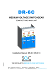
DF-3 MEDIUM VOLTAGE SWITCHGEAR THE MODULAR CONCEPT Installation Manual: DF-3 SGC - SwitchGear Company - Moorstraat 24 - B-9850 Nevele - Belgium +32 (0)9/321.91.12 - Fax +32 (0)9/321.91.13 - e-mail: [email protected] website: www.switchgearcompany.eu © 2012 SGC - SwitchGear Company. All rights reserved. The information provided herein may not be reproduced and/or (re)published in any way and by any means (electronic or mechanical), without the prior, explicit written authorization of SGC - SwitchGear Company. The information provided herein is based on general data concerning the construction, known at the time of publication, and concerning the qualities of the material and working methods. Consequently, the right to make changes is reserved. The information contained within is applicable to the standard version of the DF-2 medium-voltage switchgear. Therefore, SGC - SwitchGear Company cannot be held liable for any damage resulting from specifications that differ from the standard version of the DF-2 medium-voltage switchgear. The available information has been assembled with the greatest possible care, but SGC - SwitchGear Company cannot be held liable for any mistakes in the information, or the consequences thereof. The user names, trade names, trademarks, etc., used by SGC - SwitchGear Company cannot, in accordance with the legislation concerning the protection of trademarks, considered to be free. DW612312 ii CONTENTS CONTENTS ...................................................................................................iii PREFACE.......................................................................................................v About this manual .................................................................................................................... v Pictograms and safety symbols in and on the medium voltage switchgear............................... v Pictograms used in this manual ...............................................................................................vi Related documentation ............................................................................................................vi Service and technical assistance ............................................................................................ vii General safety directions and instructions ............................................................................... vii Intended use .......................................................................................................................... viii 1 Installation ........................................................................................... 1-1 1.1 1.1.1 1.1.2 1.1.2.1 1.1.2.2 1.1.2.3 1.1.2.4 1.1.2.5 1.1.2.6 1.1.2.7 Safety guidelines – installation ............................................................................ 1-1 General ............................................................................................................... 1-1 Recommendations – installation room................................................................. 1-1 Floor surface ....................................................................................................... 1-1 Environmental conditions .................................................................................... 1-2 Air circulation ...................................................................................................... 1-2 Free height of the installation area ...................................................................... 1-3 Dimensions of the access doors to the installation area ...................................... 1-3 Free passage in front of the cubicles ................................................................... 1-3 Internal arc resistance ......................................................................................... 1-4 2 Positioning........................................................................................... 2-1 2.1 2.2 2.2.1 2.2.1.1 2.2.1.1.1 2.2.1.1.2 2.3 2.3.1 2.3.1.1 2.3.1.2 2.3.1.3 2.3.1.4 2.3.1.5 2.3.1.6 2.3.1.7 2.3.1.8 2.3.2 2.3.2.1.1 2.3.2.1.2 2.3.3 2.3.3.1.1 2.3.3.1.2 2.3.4 2.3.4.1.1 2.3.4.1.2 2.4 2.4.1.1 2.4.1.2 2.4.1.3 DW612312 Anchoring the cubicle .......................................................................................... 2-1 Assembling the cubicles ...................................................................................... 2-2 Coupling cubicles ................................................................................................ 2-2 Kit DD003640 ...................................................................................................... 2-2 Preparations........................................................................................................ 2-2 Assembly guidelines ........................................................................................... 2-3 Assembling the bus bars ..................................................................................... 2-6 Medium-voltage switchgear 630 A – available bus bar kits .................................. 2-7 Kit DD003660 (DF-3 A/P 375) ............................................................................. 2-7 Kit DD003661 (DF-3 A/P 375 incl. closing piece) ................................................ 2-7 Kit DD003662 (DF-3 A/P 375 - 2KT Combination)............................................... 2-7 Kit DD005660 (DF-3 A/P 500) ............................................................................. 2-8 Kit DD005661 (DF-3 A/P 500 including closing piece) ......................................... 2-8 Kit DD005662 (DF-3 A/P 500 - 2KT Combination)............................................... 2-8 Kit DD003663 (COUPLING DF-3 A/P 500 - DF-3 A/P 375) ................................. 2-9 Kit DD003664 (COUPLING DF-3 A/P 500 - DF-3 A/P 375 incl. closing piece) .... 2-9 Medium voltage switchgear with two cubicles ................................................... 2-10 Preparations...................................................................................................... 2-10 Bus bars assembly guidelines ........................................................................... 2-10 Medium voltage switchgear with three (or any other odd number of) cubicles ... 2-11 Preparations...................................................................................................... 2-11 Bus bars assembly guidelines ........................................................................... 2-11 Medium voltage switchgear with four (or any other even number of) cubicles ... 2-12 Preparations...................................................................................................... 2-12 Bus bars assembly guidelines ........................................................................... 2-12 Assembly of the end panels .............................................................................. 2-13 Kit DD090610 (End plate Left - Right) ............................................................... 2-13 Preparations...................................................................................................... 2-13 Assembly guidelines end panel ......................................................................... 2-14 iii 2.5 2.6 2.6.1.1 2.6.1.2 2.6.1.3 2.7 2.8 Assembly of the front panels ............................................................................. 2-15 Assembly of the bottom panels ......................................................................... 2-16 Kit DD003690 (Bottom plate DF-3 A/P 375) ...................................................... 2-16 Preparations...................................................................................................... 2-16 Assembly guidelines bottom plates ................................................................... 2-17 Putting the door back in....................................................................................... 2-2 Measuring the phase sequence .......................................................................... 2-2 3 PUTTING INTO SERVICE..................................................................... 3-1 4 USE....................................................................................................... 4-2 4.1 4.2 4.2.1 4.2.1.1 4.2.1.2 4.2.2 4.2.3 4.2.3.1 4.2.3.2 4.2.4 4.2.4.1 Safety guidelines – use ....................................................................................... 4-2 Operation ............................................................................................................ 4-2 Operating the combination load break switch – earthing switch........................... 4-3 Opening the load break switch and closing the earthing switch ........................... 4-3 Opening the earthing switch and closing the load break switch ........................... 4-2 Reading the capacitive voltage indicators............................................................ 4-2 Operating the combination load break switch – fuse protection ........................... 4-1 Opening the load break switch and closing the earthing switch ........................... 4-1 Opening the earthing switch and closing the load break switch ........................... 4-2 Automatic recloser for cubicle type DF-P............................................................. 4-2 How it works ........................................................................................................ 4-3 5 MAINTENANCE .................................................................................... 5-4 5.1 5.2 5.2.1 5.2.1.1 5.2.1.2 5.2.1.3 5.2.1.4 5.2.2 5.2.3 5.2.4 5.2.5 5.2.5.1 5.2.5.2 5.3 Safety guidelines - maintenance ......................................................................... 5-4 Maintenance – general ........................................................................................ 5-4 General control operations .................................................................................. 5-5 Cleaning DF-3 cubicles ....................................................................................... 5-5 Cleaning the exterior ........................................................................................... 5-5 Condensation ...................................................................................................... 5-5 Cleaning the interior ............................................................................................ 5-6 Greasing aux. earthing knife grooves & the earthing contact (if available) ........... 5-6 Switching the switches (DF-3 cubicles with a switching function) ........................ 5-1 Replacing the fuse protectors (DF-P cubicles) .................................................... 5-1 Procedure and steps to reach the bus bars in case of an internal arc.................. 5-2 Preface ............................................................................................................... 5-2 Procedure ........................................................................................................... 5-2 Unpacking ........................................................................................................... 5-3 6 DF-3 CUBICLES AND THE ENVIRONMENT ....................................... 6-4 6.1 6.2 6.3 DW612312 Packing materials ................................................................................................ 6-4 Disposal of the cubicles....................................................................................... 6-4 Recuperation of SF6 gas..................................................................................... 6-4 iv PREFACE About this manual This document is intended as a reference for qualified and trained operators to transport, install, operate and maintain the medium voltage switchgear in a safe and economical way. This document uses the term “medium voltage switchgear” to denote a random, but in actual practice, existing combination of DF-3 cubicles that, mutually coupled and connected, constitute a client-specific transformation or distribution station. See: “General description”. The chapters and sections are numbered. The page numbers (consisting of the chapter number and the page number) and the document code can be found at the bottom of every page. In the documentation the words “left”, “right”, “front” and “behind” are used to indicate a specific part of the medium voltage switchgear. The starting point is always the position of the operator, standing in front of the medium voltage switchgear, facing the switchgear. Pictograms and safety symbols in and on the medium voltage switchgear Depending on the version, the following pictograms are used on the medium voltage switchgear: WARNING High Voltage Danger Access to this cubicle is only allowed after this cubicle and both the directly adjacent cubicles (previous and next one) are voltage-free. DW612312 v Pictograms used in this manual The following pictograms apply to the medium voltage switchgear user documents: CAUTION! A procedure that can, if not carried out with the proper care, result in damage to the medium voltage switchgear, the surrounding area or the environment. WAARSCHUWING High Voltage Danger VOORZICHTIG Clamping danger Notes, suggestions and advice Ensure that the cubicle, the next one, and the previous one are voltage-free before carrying out the work described in the manual. Open both the load break switch and the earthing switch before carrying out the work described in the manual. Consult the indicated information sources first. Protect the medium voltage switchgear from water and damp. Related documentation The following technical documentation for medium voltage switchgear is available: • User’s manual: Coupling of a DF-2 cubicle to a DF-3 cubicle DW612312 vi Service and technical assistance For information concerning specific settings, maintenance or repair work that is not mentioned here, please contact SGC - SwitchGear Company. • − − When contacting SGC - SwitchGear Company, always provide the following information: Cubicle type and voltage Serial number of the cubicles General safety directions and instructions SGC - SwitchGear Company does not accept any liability for damage or injury caused by not (strictly) following the safety directions and instructions, or by negligence during the installation, the use, the maintenance, or the repair of the medium voltage switchgear and its (possibly) additional options. In case of any specific user circumstances, or in case of any additional, fitted options, extra safety instructions may be required. Please contact SGC - SwitchGear Company immediately if you encounter a potential danger during the operation of the medium voltage switchgear. The owner/operator of the medium voltage switchgear is fully responsible at all times for observing the locally applicable safety instructions and guidelines. User manual • Anyone who uses or operates the medium voltage switchgear, must be familiar with the contents of the user manual, and follow the directions contained within very closely. The owner/operator must educate the users in accordance with the user manual and he or she must obey all directions and instructions. • Never change the order of the required actions. • Always keep the user manual close to the medium voltage switchgear. Pictograms and safety symbols The pictograms, symbols and instructions applied to the medium voltage switchgear are a part of the safety equipment. They may therefore not be covered or removed, and must be present and clearly readable throughout the entire life cycle of the medium voltage switchgear. • Replace or repair unreadable or damaged pictograms, symbols and instruction immediately. Contact SGC - SwitchGear Company for replacements. Operators The execution of the work detailed herein (transport, installation, use and maintenance) is strictly reserved for trained and qualified operators, who are familiar with the dangers that may arise from operating the material. Temporary employees and personnel in training cannot operate the medium voltage switchgear under any circumstances. DW612312 vii Technical specifications • Technical specifications must not be changed. • Modification of the medium voltage switchgear (or parts thereof) is not permitted. Transport, storage, installation, operation and maintenance • See corresponding documents: − “Safety guidelines – transport” − “Safety guidelines – storage” − “Safety guidelines – installation” − “Safety guidelines – operation” − “Safety guidelines – maintenance” Intended use The medium voltage switchgear is designed exclusively for use as transformation and distribution stations, according to the guidelines and conditions provided by SGC SwitchGear Company. Every other different or extended use, does comply with the intended use. 1 SGC - SwitchGear Company does not accept any liability for damage(s) or injuries resulting from deviation(s) of the intended use. The medium voltage switchgear complies with the current norms and guidelines. See: Technical Brochure. • Operate the medium voltage switchgear strictly in a technically perfect condition, in accordance with the intended use outlined above. Leave the sealed connections entirely intact, at all times. Breaking the sealed connections irrevocably voids any guarantee claims. 1 The “Intended use” as defined in EN 292-1 “is the use for which the technical product is suited as specified by the manufacturer including his directions in the sales brochure.” In case of doubt, it is the use that can be deduced from the construction, the model and the function of the technical product that is considered normal use. Operating the product within the limits of its intended use also involves observing the instructions in the user manual. DW612312 viii 1 INSTALLATION 1.1 Safety guidelines – installation 1.1.1 General Installation of the medium voltage switchgear is reserved strictly for trained and authorized operators, who respect the locally applicable safety prescriptions & guidelines. The actual connection and first start-up is to be performed by trained and authorized personnel in service of the power supply company. • • • 1.1.2 See also: "General safety guidelines and instructions". Never leave tools or equipment behind in, or on, the medium voltage switchgear. Install the medium voltage switchgear exclusively in spaces that fully comply with the following recommendations (according to IEC 60298): Recommendations – installation room Recommendations regarding the installation room are subdivided in recommendations concerning the: • floor surface • environmental conditions • air circulation • free height of the installation area • dimensions of the access doors to the installation area • free space in front of the cubicles • internal arc resistance 1.1.2.1 Floor surface The surface fit for the medium voltage switchgear placement, needs to be sufficiently strong and perfectly flat. The maximum allowed difference in level is 2 mm/m. DW612312 1-1 1.1.2.2 Environmental conditions DF-3 cubicles have been designed for indoor installation, provided that the following environmental conditions are met: Description environmental temperature relative air humidity (%) installation altitude (m.a.s.l.) Value min. -15 °C - max. +45 °C min. 10% - max. 70% (without condensation) max. 1.000 m above sea level Table 1: Environmental conditions Consequently: • Avoid storage in dusty areas. • Avoid storage in areas with a high level of relative air humidity. • Avoid storage in areas sensitive to lightning. • Avoid storage in areas where cubicles may be exposed to corrosive gases or fluids. Contact SGC - SwitchGear Company if the cubicles need to be stored or installed in places where the required environmental conditions cannot be guaranteed. 1.1.2.3 Air circulation • • Ensure proper air circulation in the installation area Secure the air circulation openings to prevent small animals or rodents from gaining access to the installation area When the medium voltage switchgear contains one or more transformer cubicles, special attention needs to be paid to air circulation. Consult the table below to calculate the corresponding values. The table displays capacity losses with regard to the capacity of the cast resin transformers. Transformer Capacity (KVA) 100 160 250 315 400 500 630 800 1.000 1.250 1.600 2.000 P (W) 1.605 2.175 2.850 3.412 4.012 4.837 5.745 6.787 7.875 10.350 12.450 16.125 Table 2: Overview of capacity losses in cast resin transformers DW612312 1-2 1.1.2.4 Free height of the installation area The free height of the installation room has to be at least 2200 mm. Depending on the distribution network manager however, a larger minimum free height may be required. An ideal free height, universally accepted by all distribution network managers, is 2500 mm. Dry transformers with a capacity of ≥ 1250 KVA require a minimal height of at least 2500 mm. 1.1.2.5 Dimensions of the access doors to the installation area The provided height and width measurements apply to all doors that offer access to the installation room. These minimum requirements also apply if the installation room is not directly accessible from the outside. description Height of the access door Width of the access door value min. 2200 mm min. 100 mm + width of the widest cubicle Table 3: Dimensions of the access doors If the medium voltage switchgear does not contain any transformer cubicle(s), a minimal door height of 2000 mm suffices. If a transformer cubicle has been included, the dimensions of the transformer always need to be taken into account. For the correct dimensions of the different cubicles, please see: “Dimensions & Weights”. If the medium voltage switchgear is to be installed in basements, an access hatch is required, with a length and width of at least 400 mm larger than the dimensions of the largest cubicle or transformer. 1.1.2.6 Free passage in front of the cubicles The free passage in front of the cubicles depends on the composition of the medium voltage switchgear. If the medium voltage switchgear does not contain any transformer cubicle(s), the minimum free passage is 800 mm. Medium voltage switchgear with a transformer cubicle with a capacity of ≥ 1.000 KVA requires a free passage of at least 2000 mm. DW612312 1-3 1.1.2.7 Internal arc resistance To prevent major material damage, serious physical injury or electrocution in the (unlikely) event of an internal arc, the following installation guidelines apply: • Between the rear side of the cubicles and the wall of the installation room, ample free space needs to be respected, as displayed in Figure 1. This layout corresponds with an assembly where the side plates of the cubicles reach the rear side of the installation room. As a result, the free space behind the cubicles is entirely closed off. Consequently, a possible internal arc will trigger the overpressure system of the rear plates. Figure 1: Top view of installed cubicles A transformer cubicle can always be placed with its rear side against the wall DW612312 1-4 Figure 2: Minimal free height • • Anchor each cubicle of the medium voltage switchgear to the floor using 4 bolts. See 2.1 Anchoring the cubicle. Couple the cubicles mutually by using the provided fixing material. See 2.2 Assembling the cubicles. Medium voltage cubicles installed according to the aforementioned guidelines always restricts an internal arc to its compartment of origin. DW612312 1-5 2 POSITIONING 2.1 Anchoring the cubicle Figure 3: Positioning: Fastening DF-3 cubicles Consult the installation plans, the electrical schematics, and the floor plans before starting with the actual positioning of the medium voltage switchgear. For horizontal dimensions, please refer to the corresponding cubicle’s general user manual since they are cubicle-specific. Leave the indicated free space between the rear side of the cubicle and the wall of the installation room to allow the overpressure system of the rear plates to function properly. A transformer cubicle can be placed with its rear side against the wall. DW612312 2-1 • Position the first cubicle level, in its definitive place in the installation area. • Anchor the first cubicle to the floor by using four bolts. Use the provided openings as seen in figure 4. Figure 4: Positioning: Anchoring a DF-3 cubicle • Disassemble the front panel (Figure 5): Unscrew the 4 hexagonal tap bolts (C). Remove the 4 spring washers (B). Remove the front panel (A). The control and low-voltage compartment is now accessible. • Position the second cubicle against the first one. Figure 5: Disassembling front panel of DF-3 Ensure that the cubicles remain exactly aligned and perfectly level to enable a torque-free assembly of the frame, the earthing copper connection pieces, and the bus bar. Possibly included cubicle bases are factory-included and are provided individually. Install the cubicles in the correct order according to the installation plans and the electrical schematics. DW612312 2-2 • Disassemble the front panel of the second cubicle (Figure 6): Unscrew the 4 hexagonal tap bolts (C). Remove the 4 spring washers (B). Remove the front panel (A). • The control and low-voltage compartment is now accessible. Figure 6: Disassembling front panel of DF-3 cubicle • Anchor the second cubicle using the 4 floor bolts. Use the provided openings as seen in Figure 7. Figure 7: Positioning: Anchoring DF-3 cubicle • • Install each remaining cubicle accordingly and ensure that all front panels have been removed. Remove the lifting lugs on the cubicles (where available), by unscrewing the bolts. The cubicles are now ready to be a assembled. See: 2.2 Assembling the cubicles. DW612312 2-2 2.2 Assembling the cubicles When assembling the cubicles, the following important steps apply: • Coupling the cubicles • Assembling the bus bars • Assembling the end plates 2.2.1 Coupling cubicles A special kit is available, per cubicle, for mutually coupling cubicles. 2.2.1.1 Kit DD003640 Order Number Description M8x16 RIPP self-locking hexagonal flange bolt M8x20 RIPP self-locking GR040888 hexagonal flange bolt M8 RIPP self-locking GR041308 hexagonal flange nut GR040986 Quant Pos. No. ity 24 A 1 B 25 C Table 4: Contents kit DD003640 2.2.1.1.1 Preparations Ensure that the cubicle, the next one, and the previous one are voltage-free and earthed Ensure that the surface is even and level to make sure that the cubicles remain exactly aligned and perfectly level. Only then will a torque-free assembly be possible. DW612312 2-2 2.2.1.1.2 Assembly guidelines The letters referring to bolts, nuts, etc. correspond to Table 5. Figure 9: Coupling DF-3 cubicles: General overview • • • • At the height of the bus bar compartment, the cubicles need to be connected via two M8x16 RIPP self-locking hexagonal flange bolts (A) and two M8 RIPP selflocking hexagonal flange nuts (C). Torque MA equals 42Nm. In the control and low-voltage compartment, cubicles are mutually connected with the use of four M8x16 RIPP self-locking hexagonal flange bolts (A) and four M8 RIPP self-locking hexagonal flange nuts (C). Torque MA equals 42Nm. With the use of eleven M8x16 RIPP self-locking hexagonal flange bolts (A), one M8x25 self-locking hexagonal flange bolt (B) and twelve M8 RIPP self-locking hexagonal flange nuts (C), the cubicles are fastened to the cable compartment. Torque MA equals 42Nm. Before fastening the cubicles at the height of the roof panels with the use of 7 M8x16 RIPP self-locking hexagonal flange bolts (A) and 7 M8 RIPP self-locking hexagonal flange nuts (C) with torque MA equals 42Nm, the bus bar needs to be fixed into place first. DW612312 2-3 2.2.1.1.2.1 Coupling Bus Bar Compartment At the height of the bus bar compartment, the cubicles need to be connected via two M8x16 RIPP self-locking hexagonal flange bolts (A) and two M8 RIPP self-locking hexagonal flange nuts (C), see Figure 9. Torque MA equals 42Nm. Figure 8: Coupling DF-3 cubicle at the height of the bus bar compartment 2.2.1.1.2.2 Coupling low-voltage compartment In the control and low-voltage compartment, cubicles are mutually connected with the use of four M8x16 RIPP self-locking hexagonal flange bolts (A) and four M8 RIPP self-locking hexagonal flange nuts (C), see Figure 10. Torque MA equals 42Nm. Figure 9: Coupling DF-3 at the height of the low-voltage compartment DW612312 2-4 2.2.1.1.2.3 Coupling cable compartment With the use of eleven M8x16 RIPP self-locking hexagonal flange bolts (A), one M8x25 self-locking hexagonal flange bolt (B) and twelve M8 RIPP self-locking hexagonal flange nuts (C), the cubicles are fastened to the cable compartment, see Figure 11. Torque MA equals 42Nm. Figure 10: Coupling DF-3 cubicles at the height of the cable compartment Coupling the cubicles at the height of the roof occurs after fastening the bus bar, see 2.3 Assembling the Bus Bars. DW612312 2-5 2.3 Assembling the bus bars If there is ample room on the sides of the cubicles, the bus bars can be assembled via the openings in the side walls. If this is not the case the roof panel of the cubicles frequently needs to be disassembled. The roof panel is fixed with the use of self-locking hexagonal flange bolts (A), self-locking hexagonal flange nuts (B), and self-locking hexagonal plate bolts (C). Figure 11: Disassembling the roof panel The assembly method of the bus bars depends on the number of cubicles that need to be connected via the bus bars. In every installation, the bus bars always need to be assembled torque-free. Lateral traction on the drilling of the bus bars, or on the load break switch as a result of incorrectly assembled cubicles, is to be strictly avoided at all times. DW612312 2-6 2.3.1 Medium-voltage switchgear 630 A – available bus bar kits The contents of the assembly kits for bus bars can vary, depending on factors such as current capacity of the medium voltage switchgear, and the number of cubicles that need to be connected via the bus bars. Each kit is delivered separately in sturdy packaging. The hexagonal tap bolts required for connecting the bus bars need to be fastened with a torque of 35Nm. 2.3.1.1 Kit DD003660 (DF-3 A/P 375) KIT CONTENTS Order Number Description CU127353 Bus bar DF-3 L=375 Quant Pos. No. ity GR017806 Set fixing material DF-3 3 A 1 C To assemble the bus bar, see: "Bus bar assembly guidelines” for the corresponding cubicle. 2.3.1.2 Kit DD003661 (DF-3 A/P 375 incl. closing piece) KIT CONTENTS Order Number Description CU127353 Bus bar DF-3 L=375 Quant Pos. No. ity Closing piece bus bar DF-3 GR017806 Set fixing material DF-3 CU127351 3 A 3 B 1 C To assemble the bus bar, see: "Bus bar assembly guidelines” for the corresponding cubicle. 2.3.1.3 Kit DD003662 (DF-3 A/P 375 - 2KT Combination) KIT CONTENTS Order Number Description Quant ity Pos. No. CU127353 Bus bar DF-3 L=375 6 A CU127351 Closing piece bus bar DF-3 3 B GR017806 Set fixing material DF-3 2 C To assemble the bus bar, see: "Bus bar assembly guidelines” for the corresponding cubicle. DW612312 2-7 2.3.1.4 Kit DD005660 (DF-3 A/P 500) KIT CONTENTS Order Number Description CU127350 Bus bar DF-3 L=500 Quant Pos. No. ity GR017806 Set fixing material DF-3 3 A 1 C To assemble the bus bar, see: "Bus bar assembly guidelines” for the corresponding cubicle. 2.3.1.5 Kit DD005661 (DF-3 A/P 500 including closing piece) KIT CONTENTS Order Number Description CU127350 Bus bar DF-3 L=500 Quant Pos. No. ity Closing piece bus bar DF-3 GR017806 Set fixing material DF-3 CU127351 3 A 3 B 1 C To assemble the bus bar, see: "Bus bar assembly guidelines” for the corresponding cubicle. 2.3.1.6 Kit DD005662 (DF-3 A/P 500 - 2KT Combination) KIT CONTENTS Order Number Description Quant Pos. ity No. CU127350 Bus bar DF-3 L=500 6 A CU127351 Closing piece bus bar DF-3 3 B GR017806 Set fixing material DF-3 2 C To assemble the bus bar, see: "Bus bar assembly guidelines” for the corresponding cubicle. DW612312 2-8 2.3.1.7 Kit DD003663 (COUPLING DF-3 A/P 500 - DF-3 A/P 375) KIT CONTENTS Order Number Description Quant Pos. No. ity CU127352 Bus bar DF-3 L=437.5 3 A GR017806 Set fixing material DF-3 1 C To assemble the bus bar, see: "Bus bar assembly guidelines” for the corresponding cubicle. 2.3.1.8 Kit DD003664 (COUPLING DF-3 A/P 500 - DF-3 A/P 375 incl. closing piece) KIT CONTENTS Order Number Description CU127352 Bus bar DF-3 L=437.5 Closing piece bus bar DF-3 GR017806 Set fixing material DF-3 CU127351 Quant Pos. No. ity 3 A 3 B 1 C To assemble the bus bar, see: "Bus bar assembly guidelines” for the corresponding cubicle. DW612312 2-9 2.3.2 Medium voltage switchgear with two cubicles Medium voltage switchgear with two cubicles is connected to one bus bar. Figuur 12: Assembling two cubicles with one bus bar 2.3.2.1.1 Preparations Ensure that the cubicle, the next one, and the previous one are voltage-free and earthed 2.3.2.1.2 Bus bars assembly guidelines • • • Place the bars (A) on the copper (Cu) contacts (D) of the load break switches. Fasten the bars using the supplied fixing material: o Hexagonal tap bolts M10x30 (E) o Contact-locking Ø M10 (F) Fasten the hexagonal tap bolts with a torque of 35 Nm DW612312 2-10 2.3.3 Medium voltage switchgear with three (or any other odd number of) cubicles Medium-voltage switchgear where three (or any other odd number) of cubicles have to be connected via bus bars, requires the second bus bar to be affixed to the first one, the fourth to the third one, etc. This method applies to all medium voltage switchgear with an odd number of cubicles and, as a result, an even number of bus bars. Figure 13: Connecting bus bars with an odd number of cubicles 2.3.3.1.1 Preparations Ensure that the cubicle, the next one, and the previous one are voltage-free and earthed 2.3.3.1.2 Bus bars assembly guidelines • • • Place the bars (A) and the closing pieces (B) on the copper (Cu) contacts (D) of the load break switches. Fasten the bars using the supplied affixing material: o Hexagonal tap bolts M10x30 (E) o Contact-locking Ø M10 (F) Fasten the hexagonal tap bolts with a torque of 35 Nm DW612312 2-11 2.3.4 Medium voltage switchgear with four (or any other even number of) cubicles Medium-voltage switchgear where four (or any other even number) of cubicles have to be connected via bus bars, require the second bus bar to be affixed to the first one and the third one, the fourth to the third one and the fifth one, etc. This method applies to all medium voltage switchgear with an even number of cubicles and, as a result, an odd number of bus bars. Figure 14: Connecting bus bars with an even number of cubicles 2.3.4.1.1 Preparations Ensure that the cubicle, the next one, and the previous one are voltage-free and earthed 2.3.4.1.2 Bus bars assembly guidelines • • • Place the bars (A) on the copper (Cu) contacts (D) of the load break switches. Fasten the bars using the supplied affixing material: o Hexagonal tap bolts M10x30 (E) o Contact-locking Ø M10 (F) Fasten the hexagonal tap bolts with a torque of 35 Nm DW612312 2-12 2.4 Assembly of the end panels A special kit is available to assemble the left and the right end panel, for each end panel. 2.4.1.1 Kit DD090610 (End plate Left - Right) KIT CONTENTS Order Number Description Quantit Pos. No. y VO330500 VO End plate left 1 A VO330600 VO End plate right 1 B 1 C 17 D 8 E 25 F Set of fixing material for end plates M8x25 RIPP self-locking GR040989 hexagonal flange bolt M8x16 RIPP self-locking GR040986 hexagonal flange bolt M8 RIPP self-locking GR041308 hexagonal flange nut GR017807 The assembly kit also includes the following items: Order Number Description Quantity DF045600 Operational lever 1 TO400004 Sign DF-3/vital 5 1 DW612312 Manual DF-3 medium-voltage switchgear 1 2.4.1.2 Preparations Ensure that the cubicle, the next one, and the previous one are voltage-free and earthed DW612312 2-13 2.4.1.3 Assembly guidelines end panel Figure 15: Assembly end panel • • Place the end panel against the side wall of the cubicle, to match the pattern of holes on both the sidewall and the end panel. Fix the end panel by using the supplied fixing material: o By using 17 M8x25 RIPP self-locking hexagonal flange bolts (D) and 17 M8 RIPP self-locking hexagonal flange nuts (F). Torque MA equals 42 Nm. o By using 8 M8x16 RIPP self-locking hexagonal flange bolts (E) and 8 M8 RIPP self-locking hexagonal flange nuts (F), the end panel is fixed to the side wall of the cubicle. Torque MA equals 42 Nm. If the wall is not completely straight, a finishing profile needs to be installed in order to ensure a perfect sealing. DW612312 2-14 2.5 Assembly of the front panels • • Carefully check whether there are still tools or fixing materials in the operation and low-voltage compartments. Assemble the front panel (A) using the four hexagonal tap bolts (C) and the spring washers (B). After assembling the front panels, the bottom panels can be assembled. Cubicles that require a cable connection frequently have the connection of the cables installed at the same time as the assembly of the bottom panels. See: “Assembly of bottom panels”. Figure 16: Assembly front panel DF-3 DW612312 2-15 2.6 Assembly of the bottom panels Since the assembly of the bottom plates is performed simultaneously with the connection of the cables during installation, both activities are described in combination here. Under all conditions, the following applies: Connection of the cables is restricted to properly trained and authorized personnel in service of the network distributor, using exclusively the fixing materials provided by SGC - SwitchGear Company. Cables can never cross. 2.6.1.1 Kit DD003690 (Bottom plate DF-3 A/P 375) KIT CONTENTS Order Number Description DE422201 Bottom plate DF-3 A/P 375 4 A PC076604 Transit rubber 3 B 1 C 8 D 8 E 6 F 6 G GR017807 GR040979 GR041306 GR040986 GR041308 Set fixing materials bottom plates M6x20 RIPP self-locking hexagonal flange bolt M6 RIPP self-locking hexagonal flange nut M8x16 RIPP self-locking hexagonal flange bolt M8 RIPP self-locking hexagonal flange nut Quantit Pos. No. y 2.6.1.2 Preparations Ensure that the cubicle, the next one, and the previous one are voltage-free and earthed DW612312 2-16 2.6.1.3 Assembly guidelines bottom plates • Unscrew the hexagonal tap bolts, for every cable support (Figure 18 H), a couple of turns to regulate the depth of the cable support. Depending on the cable diameter, it might be necessary to disassemble the cable support entirely. • Disassemble, for every cable support, the clamp strip (Figure 18 I), or release it on one side. • Install the rear bottom plate (Figure 18 A). • Attach the bottom plate on both sides of the frame using the self-locking hexagonal flange bolt (Figure 18 D) and the self-locking hexagonal flange nut (Figure 18 E). • Use a sharp knife to make a number of cuts in the transit rubber (Figure 19 B). • Move the transit rubber over the cable bushing (Figure 19 L). • Connect the cable to the connection contact o Assemble the cable using a contact lock (Figure 19 K) and a nut (Figure 19 J). Torque MA equals 60Nm. • Move the transit rubber over the cable (Figure 19 B) at the right height. • Reassemble the clamp strip (Figure 20 I) on the cable support. Fasten the cable support by screwing in the hexagonal tap bolts (Figure 20 O) on both sides. Attach the earthing cable (Figure 20 P) to the cable support. • Figure 17: Assembly of bottom plate Figure 18: Assembly of cable Figure 19: Assembly of earthing cable DW612312 2-17 • • • • • Place the second bottom plate inside the cubicle, causing the transit rubber to be fixed into place by both bottom plates. Attach the bottom plate on both sides of the frame using the self-locking hexagonal flange bolt (Figure 21 D) and the self-locking hexagonal flange nut (Figure 21 E). Attach the second bottom plate to the rear bottom plate using the self-locking hexagonal flange bolts (Figure 21 F) and the self-locking hexagonal flange nut (Figure 21 G). Continue working according to the instructions above. Work systematically towards the door opening. Figure 20: Assembly of bottom plate After assembling the four bottom plates (and connecting the cables), the doors can now be placed back onto the cubicles. 2.7 Putting the door back in Before placing the door back, the load break switch must be in the OPEN position and the earthing switch in the CLOSED position. • • • • Carefully check whether there are still tools or fixing materials in the cable compartment and remove them if necessary. Check all connections. Attach the door (B) to the cable compartment: o Take hold of the door with both hands using the grip (D). o Carefully place the door onto the support points. o Press the door down. Lock the door using a sturdy padlock (C) on the locking clip (A). Figure 21: Placing the door back The keys can only be stored by specially designated, authorized operators DW612312 2-2 2.8 Measuring the phase sequence The phase sequence is frequently measured between DF-A cubicles. Using voltage indicators (A) on the front panel, the phase sequence can be measured easily. • Measure using a voltage meter/phase sequence indicator (B) between the corresponding phases. A phase sequence indicator (RM086000) is optionally available. If no voltage can be measured, the phase sequence is correct. To double check, the voltage between different phases can be measured. Obviously voltage does need to be measured in this case. DW612312 Figure 22: Measuring phase sequence 2-2 3 PUTTING INTO SERVICE The actual connection to the distribution grid and the first putting into service of the medium voltage switchgear can only be carried out by authorized and trained personnel in service of the power supply company, and by strictly obeying the locally applicable safety guidelines. Notes: DW612312 3-1 4 USE 4.1 Safety guidelines – use • • • See also "General safety guidelines and – use". Operating the medium-voltage switchgear is restricted to qualified and trained operators, taking into consideration the locally applicable safety prescriptions and guidelines. Make sure that during operation the door is always correctly closed and locked with a sturdy padlock. Switching with an open door is impossible. 4.2 Operation Depending on the version, the medium-voltage switchgear is equipped with (a number of) the following controls and indicators: • synoptic diagram (see "Synoptic diagram") • operational lever • load break switch (single) • earthing switch • capacitive voltage indicators • turning button to operate load break switch • low-voltage switch The function of these controls and indicators, as well as their operation, is described by their actual operation. DW612312 4-2 4.2.1 Operating the combination load break switch – earthing switch During normal operation, the position is as follows: − load break switch CLOSED − earthing switch OPEN The indicator on the synoptic diagram is placed vertically, Figure 24. In this position the earthing switch is automatically locked. It is impossible to close the earthing switch. Figure 23: Load break switch closed earthing switch open 4.2.1.1 Opening the load break switch and closing the earthing switch • • • • Place the operational lever on the operational axis of the load break switch. Turn the operational axis counterclockwise (1) until the load break switch audibly opens. The indicator on the synoptic diagram is no longer in a vertical position, the earthing switch is automatically unlocked (2). Place the operational lever on the operational axis of the earthing switch. Turn the operational axis clockwise (3) until the earthing switch audibly closes. The indicator on the synoptic diagram is now in the earthing position (4). If required, the door can now be opened. Figure 24: Opening the load break switch, closing the earthing switch Turning counterclockwise = opening switch Turning clockwise = closing switch DW612312 4-3 4.2.1.2 Opening the earthing switch and closing the load break switch • • • • • Ensure that the door do the cable compartment is closed. See: “Placing the door back”. Place the operational lever on the operational axis of the earthing switch. Turn the operational axis counterclockwise (1) until the earthing switch audibly opens. The indicator on the synoptic diagram is in the neutral position (2). Place the operational lever on the operational axis of the load break switch. Turn the operational axis clockwise (3) until the load break switch audibly closes. The indicator on the synoptic diagram will move to a vertical position (4). The cubicle is now ready to be put into service. Figure 25: Opening the earthing switch, closing the load break switch Turning counterclockwise = opening switch Turning clockwise = closing switch 4.2.2 Reading the capacitive voltage indicators The capacitive voltage indicators (A) offer the possibility to measure the phase sequence during the first operation. See: “Measuring the phase sequence”. The voltage indicators also offer the possibility to monitor (in DF-P cubicles) whether fuse protectors have been used and if (with the load break switch in the OPEN position) there is still voltage on the cables. Figure 26: Reading capacitive voltage indicators DW612312 4-2 4.2.3 Operating the combination load break switch – fuse protection During normal operation, the position is as follows: − load break switch is CLOSED − earthing switch is OPEN The indicator on the synoptic diagram is placed vertically, Figure 24. Figuur 27: Combination load break switch – fuse protection closed earthing switch open In this position the earthing switch is automatically locked. It is impossible to close the earthing switch. 4.2.3.1 Opening the load break switch and closing the earthing switch • Make an upward movement with the operational button (1) until the load break switch audibly opens. The indicator on the synoptic diagram is no longer in the vertical position, the earthing switch is automatically unlocked (2). Check using the capacitive voltage indicators whether (with the load break switch in the OPEN position) there is still voltage on the cables. The capacitive voltage indicators have to be OFF. If necessary, the door can now be opened. • • Place the operational lever on the operational axis of the earthing switch. Turn the operational axis clockwise (3) until the earthing switch audibly closes. The indicator on the synoptic diagram is in the earthing position (4). If necessary, the door can now be opened. Figure 28: Opening combination load break switch-fuse protection, closing earthing switch Turning counterclockwise = opening switch Turning clockwise = closing switch DW612312 4-1 4.2.3.2 Opening the earthing switch and closing the load break switch • Ensure that the door do the cable compartment is closed. See: “Placing the door back”. Place the operational lever on the operational axis of the earthing switch. Turn the operational axis counterclockwise (1) until the earthing switch audibly opens. The indicator on the synoptic diagram is in the neutral position (2). Place the operational lever on the operational axis of the load break switch. Turn the operational axis clockwise (3) until the load break switch audibly closes. The indicator on the synoptic diagram will move to a vertical position (4). The cubicle is now ready to be put into use. • • • • Figure 29: Opening earthing switch, closing combination load break switch-fuse protection Turning counterclockwise = opening switch Turning clockwise = closing switch 4.2.4 Automatic recloser for cubicle type DF-P The automatic recloser consists of the following main elements • Under voltage release 220 VAC • Motor operation of load break switch • Voltage detection • Battery-operated control Important notice: during manual control or during work on the medium-voltage switchgear, the operator (BA4/BA5) always needs to move the switch manualautomatic in the “manual” position, and needs to remove the key from the control to lock the control in the “manual” position. This is necessary to prevent unwanted switching. DW612312 4-2 4.2.4.1 How it works If the voltage on the grid drops, the load break switch will drop by acting on the under voltage release. When the voltage returns from the grid, the load break switch will reengage, after a specific time, set in advance. The time can be set using time relay KO2 and KO3. KO2. KO2 sets the reengagement time and KO3 prevents pumping (antipumping). A possible error (protection on the transformer) will result in disconnecting. Every error (melting of the HRC fuses, protection of transformer) is locked, which prevents reconnection. Reconnection is possible only after a local intervention by a person (BA4/BA5) who can track the error, remedy it, and afterwards push the reset button to allow for automatic reconnection after placing the “manual-automatic” switch back into the “AUT” position (see important notice earlier.) DW612312 4-3 5 MAINTENANCE 5.1 Safety guidelines - maintenance • • See also "General safety guidelines en –instructions". The detailed maintenance guidelines are restricted to authorized and trained operators, respecting the locally applicable safety prescriptions and guidelines. • All other maintenance tasks, not mentioned here, are restricted to trained and authorized service personnel (in service of the distribution company). • Ensure that the medium-voltage switchgear is voltage-free before executing any of the described maintenance operations. • Only put the medium-voltage switchgear back into operation after the front panels and doors (if applicable) have been reattached and the maintenance steps have been carefully verified. • Never leave any tools or fixing materials behind inside or on the medium-voltage switchgear. 5.2 Maintenance – general DF-3 cubicles have been designed to operate flawlessly for an extend period of time, with minimum maintenance. To ensure perfect operation, a few simple maintenance and cleaning operations are required. If proper caution is exercised, and if the prescribed operations are performed accurately, possible errors will be discovered and frequently be corrected before any failure occurs. Since service intervals depend on specific work and company circumstances, and as a result, vary wildly, no intervals are provided. The following tasks are nevertheless required: Interval Task Every two years Switching the switch(es) in DF-3 cubicles with switching function • See "§4.2 Operation". Every two years Render entire medium-voltage switchgear voltage-free • See "Safety guidelines – maintenance". Every five years Disassembling the roof panels of the cubicles (for cleaning purposes) • See "Assembly of bus bars". Ensure that the entire medium-voltage switchgear is voltagefree before disassembling the roof panels. Every ten years DW612312 Replacing the fuse protectors in DF-P cubicles • See "Replacing fuse protectors (DF-P cubicles)". 5-4 Important notice concerning RV-53 load break switch. The load break switches that are part of DF-3 cubicles require minimal maintenance. They are of the « Sealed for life » type and do not require any intervention with regard to sealing, during the entire life cycle of the switchgear. The RV-53 load break switches are developed according to IEC 62271-102 and have a mechanic life cycle of 1000 switch operations. Maintenance intervals can vary depending on the use of the load break switch. Nevertheless, regular scheduled maintenance task are still required, as described in the previous table. 5.2.1 • • General control operations Regularly perform a thorough, general visual inspection. Check whether the cables are still connected properly. 5.2.1.1 Cleaning DF-3 cubicles Contamination of the DF-3 cubicles can initially be limited by respecting the recommendations regarding the installation area. See: “Recommendations – installation area”. 5.2.1.2 Cleaning the exterior • • • First read the safety guidelines. See: “Safety guidelines – maintenance”. First clean the exterior with a lint-free cloth and a non-corrosive cleaning product. Ensure that the cleaned surfaces are completely dry. 5.2.1.3 Condensation SGC - SwitchGear Company’s equipment is tested according to IEC 60932, procedure A, level 2. These tests serve to verify the proper functioning of the equipment in the presence of condensation. To avoid condensation, it is recommended to: • Properly air the room • Properly heat the room • Ensure a proper degree of humidity If despite these measures, condensation does still appear, SGC - SwitchGear Company can optionally install heating resistors (30 W) in each cubicle. DW612312 5-5 5.2.1.4 Cleaning the interior The entire interior of the DF-3 cubicles needs to be kept free from dust, moisture, and other contaminations. This applies in particular to isolators, bus bars, equipment, and cable compartments. A clean and dust-free interior facilitates dielectric characteristics and reduces creepage current to a minimum. • • • • • • • • Render the entire medium-voltage switchgear voltage-free. See: “Safety guidelines – maintenance”. Disassemble the front panel. See: “Positioning”. Remove the door. See: “Unpacking” Clean the interior (including the cables) with a lint-free cloth and a non-corrosive cleaning product. Rub the cleaned surfaces thoroughly dry to prevent surface oxidation, copper oxidation and corrosion of the fixing materials. Check all bolt-nut connections. Assemble the front panel. Place the door back. 5.2.2 Greasing aux. earthing knife grooves & the earthing contact (if available) During installation of the medium-voltage switchgear, the auxiliary earthing knife (if available), is greased with a thin layer of SGC - SwitchGear Company grease. The periodical cleaning of the interior of the cubicles (viz. cleaning the cable compartment) is the appropriate moment to thoroughly clean and degrease these components to remove dirt attracted by the grease. In DF-P cubicles, the earthing knife grooves (A) and earthing contacts (B) of the second earthing knife (auxiliary earthing knife) need to be cleaned and regreased. • Render the entire medium-voltage switchgear voltage-free. See "Safety guidelines maintenance". • Remove the door. See "Unpacking". • Clean the earthing knife grooves (A) and the earthing contacts (B). • Reapply a 0.5 mm evenly applied layer of SGC - SwitchGear Company grease (order number: GR002002) after cleaning these components. • Install the cable compartment door. See "Placing the door back". • Lock the door with a sturdy padlock. • Put the medium-voltage switchgear back in operation. DW612312 Figure 30: Greasing the auxiliary earthing knife 5-6 5.2.3 Switching the switches (DF-3 cubicles with a switching function) Switches that are used rarely or never, need to be switched at least every two years to check the functioning of the mechanical components. See: “Operation”. 5.2.4 Replacing the fuse protectors (DF-P cubicles) The fuse protectors in DF-P type cubicles need to be replaced at least every 10 operational years, or sooner if necessary as part of a repair (e.g. after one of the fuse protectors has been used.) Always replace all three HRC-protection fuses simultaneously, even though only one of them is broken. • • • • Render the entire medium-voltage switchgear voltage-free. See: “Safety guidelines – maintenance”. Remove the door. See: “Unpacking”. Remove the three fuse protectors, starting with the front-most one: o Push fuse protector (C) from the top out of spring clamp (A) o Take the fuse protector from the bottom out of spring clamp (B). Install the new fuse protectors. Start from the rear of the cubicle and systematically work towards the door opening: Ensure that the firing pins (E) are on top. The arrow should point upward (D). o Place the fuse protector in the bottom spring clamp (B). o Push the fuse protector in the top spring clamp using a twisting motion (A). Prevent any damage and distortion of the spring clamp. • • • • Figure 31: Assembly fuses Manually check the tripping mechanism: the levers (F) cannot be stuck or show any signs of a defect. Place the door to the cable compartment back. See "Placing the door back". Lock the door with a sturdy padlock. Put the medium-voltage switchgear back in operation. DW612312 5-1 5.2.5 Procedure and steps to reach the bus bars in case of an internal arc 5.2.5.1 Preface The following procedure describes the method and a list of steps to securely reach the bus bars in the unlikely event that an internal arc arises in the bus bars of a DF-3 type cubicle. 5.2.5.2 Procedure 1. Render the entire cubicle voltage-free, according to the procedure “Safety guidelines - maintenance”. 2. Disassemble the roof by removing all fixing points. 3. Remove the roof 4. You now have access to the bus bars DW612312 5-2 5.3 Unpacking DF-3 cubicles are by default wrapped in protective foil and secured to a euro pallet. The most appropriate place to unpack the cubicles is of course the final installation area. • Cut the tie down strips used to fasten the cubicle onto the pallet. • Carefully remove the protective foil. • Examine the delivery note to ensure that the cubicle is complete. • Check the cubicle for possible (transport) damage. • Carefully lift the cubicle off the pallet. If any parts are missing or damaged, contact the transporter or SGC - SwitchGear Company. Heavily damaged cubicles always need to be returned to SGC SwitchGear Company. By request, cubicles come equipped with lifting lugs. If you use these, use strictly appropriate lifting & hoisting tools, in perfect condition and with sufficient power. Respect the applicable safety measures. Fastening the load and giving instructions to the person operating the lifting & hoisting is strictly reserved to experienced personnel, within visual and oral distance of the operator of the hoist or lift tool. • • Remove the pallet. Remove the door. o Turn the part designated for the padlock open (middle, top of the door). o Grab the handle to the cable compartment door with both hands. o Carefully take the door and move it upwards. DF-3 cubicles are equipped with a load break switch and an earthing switch and by default they are delivered in these positions: “load break switch open – earthing switch closed”. In these positions the door is always removable. • • • Place the removed door in a place where there is no risk of damage. Repeat the steps above for each separate cubicle. Disassemble any available end panels affixed to one of the cubicles After the wrapping materials are disposed in regulation with the applicable legislation, the positioning of the cubicles can begin. DW612312 5-3 6 DF-3 CUBICLES AND THE ENVIRONMENT 6.1 Packing materials Packing materials consist mainly of: • (unprocessed) wood • synthetic tie down strips • synthetic foil Ask your local sanitation services for possible recycling options or environmentally-friendly disposal of packing materials. Offer the packing materials in the prescribed manner (separated). In Belgium, Euro-pallets need to be returned to SGC - SwitchGear Company after the installation of the cubicles. 6.2 Disposal of the cubicles With regards to reusing electrical components, SF6-gas (sulfur hexafluoride) filled load break switches RV-53 can be returned to SGC - SwitchGear Company at the end of their life cycle and after being damaged. After consulting, even entire DF-3 cubicles can be returned. If this proves to be impossible, the cubicles are to be processed in an environmentally friendly way. Ask your local sanitation services for possible recycling options or environmentally-friendly disposal of packing materials. Offer the packing materials in the prescribed manner (separated). 6.3 Recuperation of SF6 gas The recuperation of SF6-gas in cubicles of the DF-3 type only concerns the load break switch type RV-53. The casing of the cast resin switch contains a gaseous volume of 0,0145 m³ gas with a pressure of 1.5 bar absolute at 20°C. Taking into account the dimensions and the volume of the gas, users are advised to have the recycling and destruction of gas-filled components done, at the end of the life-cycle, by a specialized company. In this case, the user will take into account the local regulations with regards to transport. Insofar as possible, the user will denote the predictable state of decomposition of the gas, in order to be able to provide adequate treatment. At the end of the life cycle (usually 30 years) the decomposition degree of the gas, in the case of switches, will be considered as minor (see Table 1 – section 6 IEC 61634). At the end of the life cycle of the SF6 gas filled RV-53 switches, the user can also turn to SGC SwitchGear Company in order to recycle, and recuperate and destroy the SF6 gas. DW612312 6-4 DW612312 DW612312 ©2011 SGC - SwitchGear Company 6-5