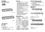
1
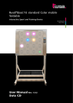
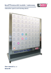
twall® Compact 32 mobile / stationary Interactive Sport and Training Device THE INTERACTIVE TOUCH WALL User Manual Rev. 1.0 Data CD twall®Compact32 mobile/stationary | User Manual Rev. 1.0 Software Documentation Hardware Documentation Table of contents: 1 1.1 Product description---------------------------------------------------------------------------------------- 4 Normal use---------------------------------------------------------------------------------------------------------4 2 2.1 2.1.1 2.2 2.2.1 Product Contents- ------------------------------------------------------------------------------------- 5 Summary of the product contents for the twall®Compact32 mobile - ---------------------------------5 Detailed list of the product contents for each assembly step---------------------------------------------5 Summary of the product contents for the twall®Compact32 stationary ------------------------------7 Detailed list of the product contents for each assembly step---------------------------------------------7 3 3.1 3.1.1 3.1.2 3.1.3 3.1.3.1 3.1.3.2 3.1.3.3 3.2 3.2.1 3.2.2 3.2.2.1 3.2.2.2 Assembly-------------------------------------------------------------------------------------------------------- 9 Assembling the twall®Compact32 mobile - ------------------------------------------------------------------9 Requirements in terms of floor space-------------------------------------------------------------------------9 Assembly principles for the profile connectors--------------------------------------------------------------9 Assembly instructions------------------------------------------------------------------------------------------ 10 Assembling the frame base----------------------------------------------------------------------------------- 10 Assembling the universal wall-------------------------------------------------------------------------------- 12 Assembling the pushbutton modules----------------------------------------------------------------------- 15 Assembling the twall®Compact32 stationary--------------------------------------------------------------- 17 Requirements in terms of floor space ---------------------------------------------------------------------- 17 Assembly instructions------------------------------------------------------------------------------------------ 17 Assembling the universal wall ------------------------------------------------------------------------------- 17 Assembling the pushbutton modules----------------------------------------------------------------------- 20 4 Maintenance--------------------------------------------------------------------------------------------------21 5 Troubleshooting--------------------------------------------------------------------------------------------21 6 6.1 6.2 Technical data------------------------------------------------------------------------------------------------22 Datasheet for twall®Compact32 mobile and stationary ------------------------------------------------ 22 Datasheet for accessories-------------------------------------------------------------------------------------- 22 7 Operating the twall® without a computer--------------------------------------------------------23 7.1 Executing twall® programmes------------------------------------------------------------------------------- 23 7.2Viewing high scores-------------------------------------------------------------------------------------------- 24 7.3 Settings----------------------------------------------------------------------------------------------------------- 24 8 8.1 8.2 8.2.1 8.2.2 8.2.3 8.3 8.4 8.4.1 8.4.2 8.4.3 8.4.3.1 8.4.3.2 8.4.4 8.4.5 8.4.6 8.4.7 8.5. Operating the twall® with a computer-------------------------------------------------------------25 Connecting to the computer---------------------------------------------------------------------------------- 25 Driver installation----------------------------------------------------------------------------------------------- 25 Driver installation under Microsoft Windows XP --------------------------------------------------------- 25 Driver installation under Microsoft Windows Vista®- ---------------------------------------------------- 26 Driver installation under Windows 7®- --------------------------------------------------------------------- 27 Software installation------------------------------------------------------------------------------------------- 28 Description of the software----------------------------------------------------------------------------------- 29 The start page--------------------------------------------------------------------------------------------------- 29 Programme settings-------------------------------------------------------------------------------------------- 29 Executing twall® programmes-------------------------------------------------------------------------------- 29 Saving programmes on the twall®--------------------------------------------------------------------------- 30 High scores------------------------------------------------------------------------------------------------------- 31 Simulating new twall® programmes------------------------------------------------------------------------- 31 Creating new twall® programmes--------------------------------------------------------------------------- 32 Editing twall® programmes----------------------------------------------------------------------------------- 34 Editing sound sets---------------------------------------------------------------------------------------------- 34 Firmwareupdate------------------------------------------------------------------------------------------------- 35 9 Service----------------------------------------------------------------------------------------------------------36 Annex: Exploded views E| 3 twall®Compact32 mobile/stationary | User Manual Rev. 1.0 Hardware Documentation 1 Product description The twall® is an interactive sports device which uses light impulses to generate motion sequences in a specific way. Spatial movements are simulated using illuminated push-buttons which are switched off by touch. It can be used to train for condition, flexibility, the ability to react and, if required, specific muscular endurance, depending on the training programme. The different elements can react either in a preprogrammed or random sequence and position and at a preprogrammed or random speed. The task is always the same, the touch pads have to be deactivated by touching them briefly (T=TOUCH). Depending on the module version, software-controlled programme sequences enable both individual training and group training. By means of the individual control of each touch pad element, it is possible to adjust the training area of the twall® to body size, reaction radius and visual perception area, as well as to the tactile situation of those training. In addition, the product version twall® color allows the inclusion of cognitive tasks. Moreover, the small size of the training module means that it can easily be incorporated into existing room designs. 1.1 Normal use The twall® may only be used as an incentive for people to exercise or to generate light effects. It is the responsibility of the operator to check the suitability of the training programme for the users. Only the mains adaptor supplied with the twall® may be used to operate it. The twall® complies with the threshold values of EN55022, class A with regard to highfrequency emitted interference. Other devices such as heart pacemakers may be affected by it. Continuous operation of all or individual touch pads is not permissible, as this can lead to overheating of the LED modules. Games programmes which force the lights of one or more of the touch pads to illuminate for longer than two minutes are not permissible and invalidate the guarantee. 4 |E twall®Compact32 mobile | User Manual Rev. 1.0 2 Product Contents 2.1 Summary of the product contents for twall®Compact32 mobile A1 1 A2 1 A3 2 A4 4 x x x x frame base universal wall mount touch pads weights B1 1 x stainless steel frame part, left B2 1 x stainless steel frame part, right with control unit, socket for the power supply and switches (possibly also connections for accessories, e.g. active speakers or headphones) B3 2 x stainless steel frame parts (top/bottom) C Accessories (included in the product contents) D Tools required (not included in the product contents) E User manual and data CD 2.1.1 Detailed list of the product contents for each assembly step A1 1 A1a 1 A1b 1 A1c 2 A1d 2 A1d 4 A1f 4 A1g 2 x x x x x x x x frame base comprising: frame base profile frame base profile frame base profiles frame base profiles profile brackets brackets for bracket bars bracket bars (45 (45 (45 (45 (30 x x x x x 90 90 90 90 30 x x x x x 2023) mm 1933) mm 1055) mm 910) mm 5) mm (40 x 40 x 900) mm Assembling the frame base in three stages: I. Connecting the frame base profiles 20 x profile connectors (of which 4 are used for the side stands of the universal wall attachment on the frame base) 4 x rubber feet (black) 4 x protective caps (black, plastic) II. Attaching the profile brackets to the frame base 12 x M8x16 flange button head screws with hexagon socket (3 per bracket) 12 x M8 T-nuts (3 per bracket) III. Attaching the hinges to the bracket bars 16 x aligning blocks for hinges 4 x thread inserts for hinges 4 x M8x25 cylinder screws with hexagon socket for attaching the hinges to the bracket bars 4 x washers (Schnorr washers) 4 x M8x16 cylinder screws with hexagon socket for attaching the hinges to the frame base and to the universal wall 4 x washers (Schnorr washers) 4 x M8 T-nuts for attaching the hinges to the frame base and to the universal wall A2 1 x universal wall comprising: A2a 2 x side stands (45 x 90 x 1776) mm A2b 1 x cover 8 mm groove width (continued on next page) E| 5 twall®Compact32 mobile | User Manual Rev. 1.0 A2c 4 x frame parts, long (45 x 45 x 1933) mm (of which 1 with preinstalled PVC installation channel) A2d 1 x frame part, short (45 x 45 x 840) mm A2e 4 x brackets I. Assembling the frame parts 8 x profile connectors 2 x protective caps (black, plastic) 4 x PVC combi profiles (light grey) II. Attaching the brackets to the frame parts 16 x M6 T-nuts 16 x M6x14 flange button head screws with hexagon socket III. Attaching the bracket bars (parts contained in the frame base assembly) Assembling the universal wall in three stages: A3 2 x touch pads comprising: A3a 1 x touch pad, left, with distributor board A3b 1 x touch pad, right, with distributor board and input filter I. Attaching the touch pads 4 x M8 T-nuts 4 x M8x30 cylinder screws with hexagon socket 4 x washers II. Connecting the touch pads with the control unit 8 x 14-wire ribbon cables for connection to the distribution boards identified with K01-04, K15-18 2 x 26-wire ribbon cables for connection to the control unit (A and B) 1 x 2-pin power supply cable with connectors 1 and 2 in preinstalled PVC installation channel Assembling the touch pads in two stages: A4 4 x weights B1 1 x stainless steel frame part, left B2 1 x stainless steel frame part, right, with control unit, socket for the power supply and switches (possibly also connections for accessories, e.g. active speakers or headphones) B3 2 x stainless steel frame parts (top/bottom) C Accessories (included in the product contents) C1 1 x supply cable (with Euro plug) C2 1 x USB cable (A/B) C3 1 x AC adaptor (mains adaptor) C4 1 x set of Allen keys (4 mm, 5 mm, 6 mm) D Tools required (not included in the product contents) Stepladder Spirit level Measuring tape Slotted screwdriver 9 mm E User manual and data CD 6 |E Assembling the stainless steel frame parts: 10 x M6x10 oval head screws with hexagon socket twall®Compact32 stationary | User Manual Rev. 1.0 2.2 Summary of the product contents for twall®Compact32 stationary A2 1 x universal wall A3 2 x touch pads B1 1 x stainless steel frame part, left B2 1 x stainless steel frame part, right with control unit, socket for the power supply and switches (possibly also connections for accessories, e.g active speakers or headphones) B3 2 x stainless steel frame parts (top/bottom) C Accessories (included in the product contents) Tools required (not included in the product contents) D E 2.2.1 Detailed list of the product contents for each assembly step User manual and data CD A2 1 x universal wall comprising: A2a 2 x side stands (45 x 90 x 1776) mm A2b 1 x cover 8 mm groove width A2c 4 x frame parts, long (45 x 45 x 1933) mm (of which 1 with preinstalled PVC installation channel) A2d 1 x frame part, short (45 x 45 x 840) mm A2e 4 x brackets (28 x 28) mm A2f 4 x brackets for wall assembly (86 x 86 x 43) mm Assembly in four steps: I. Assembling the frame parts 8 x profile connectors 2 x protective caps (plastic, black) 4 x PVC combi profiles (light grey) II. Attaching the brackets to the frame parts 8 x M6 T-nuts 8 x M6x14 flange button head screws with hexagon socket III. Attaching the brackets for the wall assembly 8 x M8x20 Verbus-Ripp screws with hexagon socket 8 x M8 T-nuts IV. Assembling the universal wall 4 x 12x80 plastic dowels 4 x 10x100 hexagon head cap wood screws with hexagon drive A3 A3a A3b 2 x touch pads comprising: 1 x touch pad, left, with distribution board 1 x touch pad, right, with distribution board and input filter Assembling the touch pad in two stages: I. Attaching the touch pads 4 x M8 T-nuts 4 x M8x30 cylinder screws with hexagon socket 4 x washers E| 7 twall®Compact32 stationary | User Manual Rev. 1.0 II. Connecting the touch pads with the control unit 8 x 14-wire ribbon cables for connection to the distribution boards identified with K01-04, K15-18 2 x 26-wire ribbon cables for connection to the control unit (A and B) 1 x 2-pin power supply cable with connectors 1 and 2 in preinstalled PVC installation channel B1 1 x stainless steel frame part, left B2 1 x stainless steel frame part, right with control unit, socket for the power supply and switches (possibly also connections for accessories, e.g. active speakers or headphones) B3 2 x stainless steel frame parts (top/bottom) Assembling the stainless steel frame parts: 10 x M6x10 oval head screws with hexagon socket C C1 C2 C3 C4 Accessories (included in the product contents) 1 x supply cable (with Euro plug) 1 x USB cable (A/B) 1 x adaptor (mains adaptor) 1 x set of Allen keys (4 mm, 5 mm, 6 mm) D Tools required (not included in the product contents) Stepladder Spirit level Measuring tape Impact drilling machine Percussion drill 12 mm 17 mm spanner Torque spanner User manual and data CD 8 |E E twall®Compact32 mobile 3 | User Manual Rev. 1.0 Assembly CAUTION: Before using for the first time, the twall®Compact32 and the control unit should be acclimatised for 2 hours. Also ensure that no condensation present. 3.1 Assembling the twall®Compact32 mobile 3.1.1 Requirements in terms of floor space 3m One prerequisite for assembly is a firm, level standing surface covering at least 3 m x 3 m (Fig. 3.1-1). This must be able to support a weight of approx. 231 kg. Gestellfuß 3.1.2 3m At least 2 people and the following tools are required for setting up the twall: twall® Allen key 4 mm included in the Allen key 5 mm product contents Allen key 6 mm Stepladder Spirit level Measuring tape Slotted screw driver 9 mm training area Trainingsfläche Fig. 3.1-1 Assembly principles for the profile connectors Set screwt Marks on the cross-piece (must face in the direction of the stay!) Cross-piece Countersink Flute Marks on the stay (must face in the direction of the cross-piece!) Stay neck Fig. 3.1-2 Stay NOTE: For a better understanding of the assembly process for the twall®Compact32, an exploded view of the individual assembly steps is included with this manual. E| 9 twall®Compact32 mobile 3.1.3 | User Manual Rev. 1.0 Assembling instructions 3.1.3.1 Assemble the frame base I. Connecting the frame base profiles: Step Remove the packaging material. This can be used as an underlay to avoid scratches and damage during assembly. Step Before starting to assemble the frame base A1 (Fig. 3.1-3), attach all the profile connectors to the locations provided for them in the frame base profiles. There should be 4 profile connectors remaining for the side stands of the universal wall. Please ensure that the countersink faces the cross-piece. This is indicated by the marks on the stay (Fig. 3.1-2). The set screw in the cross-piece is now screwed in slightly with the appropriate Allen key. In so doing, the stay is pushed automatically into the profile. It is important that the neck of the stay is still visible (Fig. 3.1-4) in order that it can be inserted later into the guide grooves (Fig. 3.1-5). When screwing it in, it may be necessary to press the stay lightly against the cross-piece. Step Push the two base frame profiles A1d into the guide grooves of the base frame profiles A1a and A1b (Fig. 3.1-5). Ensure that the cross-pieces of the profile connectors face inwards in the profiles A1d and the cross-pieces of the profile connectors face outwards in profile A1b. Step Push the frame base profiles A1c from right and left into the guide grooves of the frame base profile A1a so that the outer edges of the profiles are flush with one another. Please ensure that the cross-pieces of the profile connectors face outwards in this case. Now firmly tighten the profile connectors with the appropriate Allen key (approx. 25 Nm). Fig. 3.1-3 Cross-piece Stay neck Fig. 3.1-4 A1a A1c A1b A1d Guide grooves side Operator side Operator Fig. 3.1-5 Step Measure the distance between the profiles A1c and A1d. The distance from each inner edge to inner edge must be 42 cm. When the frame base profiles A1c and A1d have been attached at the correct distance, all the remaining profile connectors can also be firmly screwed in (approx. 25 Nm) (Fig. 3.1-6). Fig. 3.1-6 10 |E twall®Compact32 mobile | User Manual Rev. 1.0 Step Attach the 4 rubber feet to the underneath of the frame base (Figs. 3.1-7 and 3.1-8). Straighten the frame base so that the overlaying profiles face upwards and push the feet on the outer edges at the bottom into the grooves of the frame base profiles A1c. Lay the frame base back down again. Fig. 3.1-7 Fig. 3.1-8 II. Fitting the profile bracket on the frame base: Step The 4 profile brackets A1e are attached to the insides of the frame bases A1c and A1d (Fig. 3.1-9). To do this, insert the 12 M8 T-nuts into each of the bottom grooves of the frame base profiles (3 T-nuts per profile side or bracket). The T-nuts are to be inserted with the flute or ball downwards through a half-rotation into the guide grooves (Figs. 3.1-10 and 3.1-11). The positioning of the brackets is now estimated in the centre and the T-nuts are aligned accordingly. As the weights will subsequently rest on the profile brackets, the brackets should be positioned with the surface facing upwards to the user. The brackets are now screwed tightly with the 12 M8x16 flange button head screws (3 per bracket) into the T-nuts. Profilwinkel Fig. 3.1-9 Fig. 3.1-10 Feder Fig. 3.1-11 Fig. 3.1-11 III. Attaching the brackets to the bracket bars: Step First of all, the 4 thread inserts are screwed with a 9 mm slotted screwdriver into the open ends of the bracket bars A1g. The brackets A1f must now be attached to the bracket bars. To do this, attach the brackets to the bracket bars and screw these in with the 4 M8x25 cylinder screws, the washers and the appropriate Allen key (Figs. 3.1-12 and 3.1-13). Ensure that the brackets are attached facing in the right direction at the ends of the bracket bars. To simplify the procedure, we recommend attaching the bracket bars only after the universal wall has been assembled. Fig. 3.1-12 Fig. 3.1-13 E| 11 twall®Compact32 mobile | User Manual Rev. 1.0 3.1.3.2 Assembling the universal wall I. Assembling the frame parts The aluminium frame serves as a frame for the twall®Compact32, so that it can be freestanding (Fig. 3.1-14). Step Set up the frame base A1 on the floor space so that the projecting end of the frame base faces the operator side (Fig. 3.1-14). A level floor surface is crucial in order that it doesn't stand crookedly. Before starting to assemble the universal wall, attach all the profile connectors to the locations provided for them in the side stands and frame parts. The 4 profile connectors remaining when assembling the frame base are for the attachment of the side stands. Please ensure that the countersink faces the cross-piece in this case as well. This is indicated again by the marks on the stay (Fig. 3.1-2). The set screw in the cross-piece is now screwed in slightly with the appropriate Allen key. In so doing, the stay is pushed automatically into the profile. It is important that the neck of the stay is still visible in order that it can be inserted later into the guide grooves (Fig. 3.1-15). When screwing it in, it may be necessary to press the stay lightly against the cross-piece. Step The side stands A2a are pushed from the front into the guide groove of the frame base (Fig. 3.1-15). Ensure that the cross-pieces of the profile connectors each face outwards. The side stands are pushed into the guide groove until they are flush with the front cross bar (Fig. 3.1-16). The profile connectors are now tightened firmly with the appropriate Allen key (approx. 25 Nm). Then attach the 4 black protective caps onto the ends of the frame base profiles A1c and A1a. 12 |E Step 11 A long frame part A2c is inserted into the front guide groove (starting from the operator) between the side stands down to the frame base and then screwed in using the profile connectors (Fig. 3.1-17). Please ensure that the cross-pieces of the profile connectors face to the back. Operator side Fig. 3.1-14 Guide grooves Fig. 3.1-15 Operator side Fig. 3.1-16 Fig. 3.1-17 twall®Compact32 mobile Step 13 Another long frame part A2c is now inserted downwards into the front groove between the side stands so that it slots in with the cover A2b. Please ensure that the cross-pieces of the profile connectors face to the back. You should now screw these tightly (approx. 25 Nm). Step 15 Insert another 2 T-nuts into the short frame part you have just fitted, this time 1 top left and 1 top right. Then insert the long frame part A2c with the preinstalled PVC installation channel downwards into the front groove between the side stands until it rests on the short frame part. Ensure that the PVC installation channel faces to the rear (!). Insert 2 T-nuts into the bottom groove of the long frame part and align this accordingly. The distance from the inside edge of the side stands to the centre of the screws is 930 mm in each case. Now attach another 2 brackets A2e to the short and long frame parts (Figs. 3.1-21 and 3.1-22). Fig. 3.1-19 m m Step 14 : To assemble the brackets A2e, you need 16 M6 T-nuts and M6x14 flange button head screws. Measure the long frame part A2c which you have just fitted to the cover. The distance from the inside edge of the side stands to the centre of the screws is 930 mm in each case. Insert 2 T-nuts into the top groove of the long frame part and align this accordingly. The T-nuts are to be inserted with the flute or ball downwards through a half rotation into the guide grooves (Fig. 3.1-19). Now insert 2 T-nuts into the groove of the short frame part A2d, 1 at the bottom left and 1 at the bottom right. The distance from the inside edge of the side stands to the centre of the guide groove is 967 mm. Now place the short frame part A2d in the middle on the long frame part A2c and attach a bracket A2e using the screws on the left and right (Fig. 3.1-20). 7 96 II. Fitting the brackets to the frame parts: m Fig. 3.1-18 m Step 12 The cover A2b is also inserted into the front guide groove (starting from the operator) between the side stands and down to the long frame part A2c (Fig. 3.1-18). Ensure that the cover slots into the groove correctly. 0 User Manual Rev. 1.0 93 | Fig. 3.1-20 Fig. 3.1-21 Fig. 3.1-22 E| 13 twall®Compact32 mobile . Then screw the profile connectors of the long frame part A2c to the sides using an appropriate Allen key (approx. 25 Nm). Ensure they are aligned horizontally to guarantee that the touch pads fit exactly (spirit level). | User Manual Rev. 1.0 Bracket bar Step 16 Repeat steps 14 and 15 with the remaining frame parts A2c and A2d. III. Attaching the bracket bars: The bracket bars A1g are now fitted on the rear part of the frame base A1 and to the reverse of the side stands A2a (Fig. 3.1-23). Frame base Fig. 3.1-23 Step 17 Position a T-nut in each of the guide grooves of the frame base profile A1c. Place the brackets on the guide grooves of the frame base profiles A1c. Screw the bracket bars to the frame base using the M8x16 cylinder screws and the washers. To make assembly easier, you can move the opposite end of the bracket bar in each case to the back. Step 18 Then connect the bracket bars fitted to the frame base A1g to the side stands (Fig. 3.1-24). To do this, insert the 2 M8 T-nuts into the guide grooves on the reverse of the side stands (1 T-nut per side). Using the M8x16 cylinder screws and the washers, screw the brackets of the bracket bars onto the side stands. Step 19 The 4 weights A4 are now placed in the rear part of the frame base (Fig. 3.1-25). When doing so, observe the standard health and safety regulations (20 kg per weight). Step 20 Finally, place the 2 black protective covers onto the top edges of the side stands and press the 4 PVC combi profiles into the side stands' guide grooves, which are facing outwards, (above the cross-pieces of the profile connectors, 2 on the right and 2 on the left). Fig. 3.1-24 Fig. 3.1-25 CAUTION: Finally, check whether all the profile connectors on the frame base and on the aluminium frame are screwed in firmly (25 Nm). 14 |E twall®Compact32 mobile | User Manual Rev. 1.0 3.1.3.3 Assembling the touch pads If all the steps up to now have been carried out properly, the construction should be as shown in Fig. 3.1-26 and you can start to assemble the touch pads. I. Attaching the touch pads: Step 21 Before attaching the touch pads to the universal wall, insert all the required M8 T-nuts into the front guide grooves of the side stands. These should be inserted into the guide grooves according to the position of the boreholes of the pushbutton module. II. Connecting the touch pads to the control unit: Step 24 There are 4 14-wire ribbon cables on each push button module which are used for connecting the distributor boards. The cables are labelled with K 0.1 - 0.4 and K 1.4 - 1.8 as well as the respective connector position. The ribbon cables must now be inserted on the distributor boards. The board for the right 2 touch pads is located on the top right touch pad and for the left side on the top left touch pad (Fig. 3.1-27). Fig. 3.1-26 Control unit Distribution board right left Ribbon cable Fig. 3.1-27 CAUTION: The connectors and cables are numbered for this purpose and must be connected precisely in accordance with the numbering (Fig. 3.1-30)! Step 26 : Attach the connectors of the ribbon cables "A" and "B" with the control unit in the correct frame part as shown in (Fig. 3.1-29) . Ensure that ribbon cable "B" is inserted into the slot at the top left. Ribbon cable "A" is to be inserted in the slot located at the bottom left . Fig. 3.1-29 E| 15 twall®Compact32 mobile | User Manual Rev. 1.0 Step 27 : Now connect the power supply for the touch pad. The positions of the connectors are shown in Fig. 3.1-30. First of all, attach connector 1 (top left touch pad) with connector 2 (top right touch pad underneath the distribution board). Then attach connector 3 (top right pushbutton module above the input filter) with the control unit in the stainless steel frame part B2. Fig. 3.1-30 Connector 1 right frame side Connector 3 Connector 2 two-pin power cable Cover with control unit Fig. 3.1-30 CAUTION: Ensure the correct polarity when plugging in the ribbon cable and do not use force! Ensure that you handle the ribbon cable with great care. Avoid pulling hard on the cable or twisting it, especially near the connector plug. Also, ensure that the cables are inserted through the corresponding slots in the frame parts in order to avoid squashing the cables. Step 28 The side frame parts B1 and B2 and/or the top and bottom frame parts B3 are to be screwed together with the threaded sleeves of the touch pads (Fig. 3.1-31). To do this, use the 10 M6x10 oval head screws provided. Remove the protective foil on the frame parts before screwing the frame parts tightly. Step 29 After screwing on the frame parts, prepare the device for operation as follows: Plug in the low-voltage plug of the 24 V mains adaptor supplied C3 into the socket of the twall®. Connect the power cable C1 with a power outlet and switch the twall® on (Fig. 3.1-32). Fig. 3.1-31 Fig. 3.1-32 16 |E Gestellfuß twall®Compact32 stationary | User Manual Rev. 1.0 3.2 Assembling the twall®Compact32 stationary 3.2.1 Anforderungen für die stationäre Montage Attaching the twall® is the responsibility of the operator. The twall® may only be attached to even and stable walls. The setting up of the universal wall on the floor must be guaranteed. If the condition of the wall is not known, an expert must be called in for advice if necessary. A double covering must be provided with plasterboard walls. Only dowels and screws from the enclosed stationary kit or equivalent assembly elements may be used. The secureness of the mounting must be checked on a regular basis (Figs. 3.2-1 and 3.2-2). If fastening elements should loosen, there must be no further use of the twall® until repairs have been carried out. On-site assembly can be provided by the supplier on request. For assembling the twall®, at least 2 people and the following tools are required: Allen key 4mm included in the Allen key 5mm product contents Allen key 6mm Stepladder Spirit level Measuring tape Impact drilling machine Percussion drill 12 mm 17 mm spanner Torque spanner 3.2.2 twall® training area Abb. 3.2-1 Fig. 3.2-1 ground floor Fig. 3.2-2 Assembly instructions 3.2.2.1 Assembling the universal wall I. Assembling the frame parts Step 1 Remove the packaging material. This can be used as an underlay to avoid scratches and damage during assembly. Step 2 Before starting to assemble the universal wall A2 (Fig. 3.2-3) , first of all attach all 8 profile connectors to the long frame parts A2c. Please ensure that the countersink of the profile connector faces the cross-piece. This is indicated once again by the marks on the stay. The set screw is now screwed in slightly with the appropriate Allen key. In so doing, the stay is pushed automatically into the profile. It is important that the neck of the stay is still visible in order that it can be inserted later into the guide grooves (Fig. 3.2-4). When screwing it in, it may be necessary to press the stay lightly against the cross-piece. Fig. 3.2-3 Marking on the cross-piece Marking on the stay Stay neck Fig. 3.2-4 E| 17 twall®Compact32 stationary | User Manual Rev. 1.0 NOTE: The universal wall is constructed in such a way that the side on which the touch pads are subsequently attached faces downwards in the direction of the floor. Accordingly, the cross-pieces should face upwards when the profile connectors are attached. Step 3 Push a long frame part A2c into the bottom guide groove (on the floor) between the side stands A2a until the ends are flush. Please ensure that the cross-pieces of the profile connectors face upwards (to you) (Fig. 3.2-5). Now screw on the profile connectors (approx. 25 Nm). Step 4 Push the cover A2b into the bottom groove between the side stands as well and it should slot into the guide groove of the long frame part A2c . Step 5 Then attach another long frame part A2c to the bottom groove between the side stands so that it slots in to the cover (Fig. 3.2-6). Please ensure that the cross-pieces of the profile connectors face upwards (to you). These should now be screwed tightly (approx. 25 Nm). II. Fitting the brackets to the frame parts: Fig. 3.2-5 Step 6 To assemble the 8 brackets A2e, you need 16 M6 T-nuts and 16 M6x14 flange button head screws. Measure the long frame part A2c which you have just fitted to the cover. The distance from the inside edge of the side stands to the centre of the screws is 930 mm in each case. Insert 2 T-nuts into the side guide groove of the long frame part and align it accordingly (the cover is slotted in on the other side of the long frame part). The T-nuts are to be inserted with the flute or ball downwards through a half rotation into the guide grooves (Fig. 3.2-7). Now insert 2 T-nuts into the groove of the short frame part A2d, 1 at the bottom left and 1 at the bottom right. The distance from the inside edge to the middle of the guide groove is 967 mm Nut Fig. 3.2-6 Fig. 3.2-7 . 18 |E twall®Compact32 stationary | User Manual Rev. 1.0 Now place the short frame part A2d in the middle on the long frame part A2c and attach a bracket A2e using the screws on the left and right (Fig. 3.2-8). Brackets Cover 930 mm Step 7 Insert another 2 T-nuts into the short frame part you have just fitted, this time 1 top left and 1 top right. Then push the long frame part A2c with preinstalled PVC installation channel into the bottom groove between the side stands until it rests on the short frame part. Please ensure that the PVC installation channel faces upwards. Insert 2 T-nuts into the side groove of the long frame part and align this accordingly. The distance from the inside edge of the side stands to the centre of the screws is 930 mm in each case. Now attach another 2 brackets A2e to the short and long frame parts (Fig. 3.2-9). Then screw the profile connectors of the long frame part to the sides using an appropriate Allen key. Please ensure they are aligned horizontally to guarantee that the touch pads fit exactly. Also ensure that the edges of the last frame part A2c are flush with the edges of the side stands A2a (Fig. 3.2-10). Please check again that all the profile connectors have been screwed on firmly (approx. 25 Nm). 967 mm Fig. 3.2-8 Fig. 3.2-9 Step 8 Place the two black protective covers onto the top ends of the side stands A2a (Fig. 3.2-11) and press the 4 PVC combi profiles into the outwards - facing guide grooves of the side stands (above the crosspieces of the profile connectors, 2 on the right and 2 on the left). Fig. 3.2-10 Fig. 3.2-11 III. Attaching the brackets for the wall assembly: NOTE: As a basic principle, the height of the brackets can vary slightly (maximum deviation = 50 mm), for example in the case of obstacles (mountings, wires) in the wall to which the device will subsequently be attached. Step 9 Insert 8 M8 T-nuts into the top guide grooves on the inside of the side stands (4 T-nuts per side) and position these so that the short frame part is attached in the middle. E| 19 twall®Compact32 stationary | User Manual Rev. 1.0 Step 10 The brackets A2f are now also attached to the top guide grooves on the insides of the side stands (Fig. 3.2-12). To do this, please use 2 M8x20 Verbus-Ripp screws per bracket and tighten these firmly (approx. 25 Nm). IV. Assembling the universal wall: Step 11 To be able to mount the universal wall to a wall, you need a hammer drill, a 12 mm impact drilling machine and appropriate protective gear. The following boreholes must be made in the wall: Distances at the wall Fig. 3.2-12 twall®Compact32 stationary Floor to centre of bottom borehole: 950 mm Centre of bottom borehole to centre of top borehole 700 mm Horizontal distance between borehole centres 1863 mm NOTE: At least a double covering must be provided with gypsum cardboard walls. The secureness of the mounting must be checked on a regular basis. Step 12 Insert the dowels supplied into the boreholes in the wall. Step 13 Lift the universal wall A2 (Fig. 3.2-13) at the top end (near the protective cover) and place it straightened with the bottom part against the wall. Now attach the universal wall frame to the wall while firmly screwing on the brackets A2f with the 4 hexagon head cap wood screws in the prepared dowels. When using a torque spanner, adjust it to 25 Nm. 3.2.2.2 Assembling the touch pads Fig. 3.2-13 I. Attaching the touch pads: (Fig. 3.2-14) Please proceed exactly as described for the mobile twall®Compact32 (Chapter 3.1.3.3). II. Connecting the touch pads with the control unit: Please proceed exactly as described for the mobile twall®Compact32 (Chapter 3.1.3.3). 20 |E Fig. 3.2-14 twall®Compact32 mobile/stationary 4 | User Manual Rev. 1.0 Maintenance Every sports device is always at the mercy of dirt and perspiration. And it's no different with the twall®. Frequent use can result in dirt deposits on the outside of the touch pads. In order to ensure a long life and a cared-for appearance for your twall®, cleaner the touch pads and the frame at least once a month (twice if used very frequently). Use a soft, non-absorbent dry cloth to do this. In the case of stubborn marks, you can also moisten the cloth with a mild household clean/disinfectant. CAUTION: never use solvents or motor spirit as this could damage the touch pads! 5 Troubleshooting Possible error sources Check whether there is a sufficient power supply. Ensure correct connection of the mains adaptor to the twall® and to the power outlet. In the case of faults, check whether there is sufficient distance between the device and components which generate powerful magnetic fields (loudspeakers, microwaves). Should liquid or a foreign object get inside the device, switch off the power to the twall® and contact a service representative. NOTE: Further assistance is available from our twall® Online Support at "www.twall.de". In the download area (see page 28, Step ,) you will find the corresponding documents for specific troubleshooting and fault repair as well as for submitting a complaint. E| 21 twall®Compact32 mobile/stationary 6 Technical data 6.1 Data sheet for twall®Compact32 mobile and stationary | User Manual Rev. 1.0 Self-sustaining, interactive, multicoloured indoor training device twall®Compact32 Integrated control and operating unit, 10 training programmes Graphic programming interface to create your own game programmes 8 x 8 touch pads Active training surface: H x W: (880 x 1760) mm Overall device dimensions (mobile): H x W x D: (1865 x 2030 x 1106) mm Overall device dimensions (stationary): H x W x D: (1770 x 2030 x 138) mm Weight in kg (mobile) approx. 170 kg Weight in kg (stationary) approx. 70 kg A total of 7 fluorescent colours available (red, green, blue and combinations) Stainless steel frame Touch pad surfaces: plastic, translucent white colour Power consumption: 120 W Power supply: 24 V (mains adaptor included in the product contents) Connection sockets for power supply and switches Freestanding (mobile) or wall assembly (stationary) Maintenance period: -- 1 x half-yearly or after 10 rentals (mobile) -- 1 x yearly (stationary) Guarantee 1 year 6.2 Data sheet for accessories Fig. 6.2-1 Supply cable with Euro plug USB cable (A /B) AC adaptor (mains adaptor) with connector (Fig. 6.2-1) • AC adaptor (mains adaptor) -- primary 90-264 V AC; 47-63 Hz -- secondary 24 V DC; 5 A -- Dimensions (W x H x D in mm): 62 x 35 x 170 -- Weight in g: approx. 530 -- Connection for Euro plug • Connector (on mains adaptor) for connection to the twall® (Figs. 6.2-2 and 6.2-3) -- Pin 1 and pin 2 + 24 V -- Pin 3 and pin 4 - 0V 22 |E Fig. 6.2-2 Fig. 6.2-3 twall®Compact32 mobile/stationary | User Manual Rev. 1.0 Software Documentation 7 Operating the twall® without a computer Using the control unit integrated in the twall® , the twall® can be fully operated without using a computer. To this end, a menu is shown on the display which can be operated using the four orange keys beneath the display. The name of the menu is always displayed in the top line. The menu item currently selected is shown with a black bar with round corners. The arrow to the right of the item indicates that this item is part of a menu which has additional subitems. The functions which can be executed with the operating keys are shown in the bottom line. Use these keys to operate the menu. When navigating the main menu and its submenus, the functions for the operating keys are assigned as follows: The [arrow down] key selects the menu item underneath the one currently selected. The [arrow up ] key selects the menu item above the one currently selected. The [ENTER] key accesses the selected submenu or activates the selected menu item. The [MENU] key exits the current menu. When activating certain menu items, the assignment of the operating keys changes. 7.1 Executing twall® Programmes In order to execute a twall® Programmes by menu, select the menu item "Programmes" in the main menu and confirm this with [ENTER]. You are now in the submenu "programme". The Programmes installed on the twall® are displayed. Select the desired programme using the arrow keys and confirm with [ENTER] to start the programme. The status of the programme is now shown on the display. The name of the loaded programme is always displayed in the top line. This is where the current programme time is displayed. Status line for player 1. The three figures mean: overall targets / targets hit / errors. Status line for player 2. This line is not shown if it is a programme for one player only. E| 23 twall®Compact32 mobile/stationary | User Manual Rev. 1.0 The layout of the operating keys is largely identical. The [ENTER] key is replaced in this screen by the [NEW] key with which the programmes can be restarted. The arrow keys load the next and/ or previous Programmesme in the list of twall® Programmes. The time starts to run as soon as the first touch pad on the twall® is pressed. The end of the programme is generally indicated by the brief flashing of all the touch pad. 7.2 Viewing high scores Viewing high scores works in a similar way to implementing programmess. In the main menu, select the menu item "High scores" with [ENTER]. The "High scores" menu immediately opens, in which a list of the installed programmess is displayed. In order to display the high scores for a specific programme, select the programme using the arrow keys and then press [ENTER] to confirm. You can now navigate through the high score list using the arrow keys. A high score is always shown on a screen page. The top line shows the programme to which the high score list relate. The placings are shown here (places 1-10). The name of the player. As on the twall® control unit it is not possible to enter a name, the name "Player" is stipulated automatically. If the twall® is controlled by the computer, other names can also be assigned (see Chapter 9.4.2) The "ID" value shows the sequence of the high score entries. The most recent entry in the lists always has the highest ID. Shown in this line is the playing time of the high score entry. Shorter times produce better placings. 7.3 Settings The "Settings" menu contains the item "Version info" under which the following information regarding the twall® can be accessed: Type of twall® (exact model designation) Hardware version Software version NOTE: Always quote this information when sending a service inquiry to IMM. 24 |E twall®Compact32 mobile/stationary 8 | User Manual Rev. 1.0 Operating the twall® with a computer The twall® is fully operational without a computer, using the integrated control unit. However, certain actions, such creating as new programmess, require the use of software. The following chapter describes how this is installed and what steps are necessary for its use. System requirements of the PC: Operation systems Windows 2000/XP/Vista/7 Microsoft .Net Runtime 2.0 (included on software-CD) Processor speed min. 1.0 GHz USB Interface Screen resolution: 1024*768 50 MByte free HDD space keyboard/ mouse NOTE: The twall® drivers/software and firmware are constantly being improved. The current version at any given time can be downloaded in the download area at www.twall.de. For this you need the serial number of your twall® which can be found on the specification plate above the [ON/OFF] switch. 8.1 Connecting to the computer The twall® is connected to the computer using USB. For this you need the USB cable C2 (included in the product contents). Insert the square plug into the corresponding socket into the twall® and the flat USB connector on the computer. When connecting the twall® to the computer for the first time, Windows will recognise this as a new device. You must now install the driver. To do this, insert the software CD into your CD/DVD drive. You need administrator rights on your computer for installation. The following five steps describe the driver installation under Microsoft Windows XP® and Microsoft Vista®. 8.2 Driver installation 8.2.1 Driver installation under Microsoft Windows XP® The first step of the installation is to select "No,not this time" in answer to whether the driver is to be searched for using Windows Update. Select "Install software automatically (recommended)". The CD will automatically search for the driver. If the required driver file "usbser.sys" is not found on your computer, you must first of all indicate its storage location yourself. The file is located on the CD in the folder entitled "Driver\winxp" or "Driver\win2k". Select the file in the "winxp" folder if you are using Windows XP or the file in the "win2k" if you are using Windows 2000®. E| 25 twall®Compact32 mobile/stationary In this dialogue box select "Continue installation". | User Manual Rev. 1.0 The installation has now completed successfully. You can now install and use the twall® software. If the twall® is connected to another USB slot, the driver is installed again. This happens automatically however. Administrator rights are required even so. 8.2.2 26 |E Treiberinstallation unter Microsoft Windows Vista® The first stage of the installation is to select "Search for and install driver (recommended)". If this dialogue does not appear, select under the green arrow "...Show other options". Select "Search for driver software on the computer (expanded)". Click on the key [Search] and select the directory: Driver\vista_32bit on the data CD. Then click on [Continue]. twall®Compact32 mobile/stationary | User Manual Rev. 1.0 Select "Install this driver software anyway". The installation of the driver for the twall® was completed successfully. The twall® can now be used. If the twall® is connected to another USB slot, the driver is installed again. This happens automatically however. Administrator rights are required even so. 8.2.3 Driver installation under Microsoft 7® Windows attempts to install the driver automatically. If unsuccessful, the following message is displayed. Continue to point 2. Start the device manager. To do this, open Start->System control ->System and security->System. A window with system information appears. Click on the left side of the page on "device manager". In the device manager, the twall® is shown under the category "Other devices" and highlighted with a yellow warning sign. Right click on "twall" and select "Update driver". The driver installation assistant is now displayed. First of all, select "Search for driver software on the computer". Secondly, enter the directory containing the driver for the twall®. E| 27 twall®Compact32 mobile/stationary | User Manual Rev. 1.0 CAUTION: Windows 7 is available in 32-bit and 64-bit versions. Select the driver directory which is appropriate for your version of Windows. If you are unsure whether your version of Windows is 32-bit or 64-bit, you can check using the system information in the previously opened window. If the correct driver was indicated, this is now installed. Confirm the warning message shown with "Install this driver software anyway". 8.3 The driver installation is now complete. Software installation To install the twall® software, insert the twall® software CD into your computer's CD drive. Now start the file TwallSetup-1.0.exe and follow the on-screen instructions. It is recommended that you select the installation type suitable for your twall®. With the installation type "Full installation", the programmes for all twall® variants are installed. However, bear in mind that a programme for twall® variant A is not necessarily compatible with twall® variant B. Select the installation type which corresponds to your twall® variant or full installation to be able to connect any twall® products After installation, three shortcuts are located in the start menu or on the desktop, which each start the twall® software to a different extent in terms of function: TWall: full function (also editing settings). TWall (only executes programmes): Allows the execution of twall® programmes on the twall® and the simulation of twall® programmes on the computer. TWall (executes and edits programmes): As 2. with the added option of editing twall® programmes. Limited software variants such as these can be used on computers installed in public areas. 28 |E twall®Compact32 mobile/stationary | User Manual Rev. 1.0 8.4 Description of the software 8.4.1 The start page After starting the software, the start page of the software is displayed. Click on the links to execute the corresponding action. 8.4.2 Programme settings After the first programme start of the twall® software, the programme settings should be adjusted. Stipulate here in which directories the twall® software is to search for programmes and/or sounds in order to complete the options displays for programmes and sounds. Add a new directory to the list using this key. The key deletes the selected entry from the list. This is where information regarding the connected twall® is displayed. This information must always be quoted in the case of service. WARNING: The list of directories for twall® programmes contains after installation only the directories of the standard programmes in the software's installation folder. Your own programmes should not be stored in these directories as they would be deleted during deinstallation. For this reason, add a directory to the list outside the twall® software installation folder (e.g. a new directory in "Own files") in which you can save self-created programmes. To save the settings, click on the [Save] key after you have made all the settings. 8.4.3 Executing the twall® programme In this mode, you can: • execute twall® programmes located on twall®. • transfer to twall® and execute programmes located on twall®. • save loaded twall® programmes. • view high scores for twall® programmes. E| 29 twall®Compact32 mobile/stationary | User Manual Rev. 1.0 List of the programmes on twall®. You can start a programme by clicking on the appropriate link. This function refreshes the list of programmes on the twall®. This optionshows all the twall® programmes which were found in the folders to be searched for twall®. Using this link, you can add to the list an individual file which is not in one of the searched folders. Click on this key to send to the twall® and start the programme s elected in the box. The [Back] key takes you back to the start page. If a programme has been loaded, the software changes to status display. The status of the programme (time elapsed, score etc.) is displayed. This is where the loaded programme can also be saved on the twall®. With the waste basket symbol, the programme site in question is emptied (deletes the programme). This fields indicates the current view of the twall®. Current playing time. Status display for player 1. With this key, the currently loaded programme is saved on the twall® (only for programmes transferred from the hard disk). Shows the high scores for the programme. Aborts the execution of the loaded programme. Clicking again on this key returns the software to the "Programmes" page. 8.4.3.1 Saving programmess on the twall® Clicking on the ["Save on twall®"] key displays a dialogue first of all in which the programme number must be indicated under which the programme is to be saved. The number corresponds to the programme number in the list of programmes available on the twall® . 30 |E twall®Compact32 mobile/stationary | User Manual Rev. 1.0 You have to enter a password to save a programme on the twall®. Enter this in the following dialogue box. NOTE: The password is located on a label which is on the last page of the user manual. Only divulge this password to people who are also allowed to save programmes on the twall®. 8.4.3.2 High scores Clicking on the [High scores] key in the status display loads the high scores for the programmes loaded. The most recent entry in the list is highlighted. The last entry added is highlighted. Empty entries. With this function, the high score list is saved as a "high scores" file. Back to status display. If the programme had been started directly from the twall®, the high scores are also read out. If the programme was transferred from the computer to the twall®, the high scores are saved automatically in a "high scores" file. In this case, it is also possible to enter a name when achieving a place in the high score list. If the programme is subsequently saved on the twall®, this high scores file can also be transferred along with the previous high scores. 8.4.4 Simulating the twall® programmes The programme function "Simulate programmes" offers you the option of executing twall® programmes on the computer without needing a twall® itself. This can be useful when newly created programmes are to be tested for example. The software switches to status display depending on the selection of the programme to be simulated. The [Save on the twall] and [High scores] functions are not possible with simulations. In contrast to the status display for programmes which are executed on the twall®, the stylised twall® is an interactive element here. Instead of pressing the touch pads on the twall®, in the simulations you click with the mouse on the corresponding graphic key fields. E| 31 twall®Compact32 mobile/stationary 8.4.5 | User Manual Rev. 1.0 Creating new twall® programmes Using the twall® programme editor software, new twall® programmes can be created. General parameters are set on the first page of the programme editor. 32 |E Under this option, the twall® type is set for which the programme is intended. Enter a time-out here for the key fields. This is the maximum time which may elapse between activating (connecting) a key field and deactivating (pressing) a key field. The time-out is indicated in milliseconds between 1 and 65,000. Longer time-outs are not permitted for reasons connected with overheating. For this reason, avoid stipulating two identical targets with so high a time-out. When a time-out is set and this field is activated, the programme aborts the execution as soon as a time-out has expired. The normal procedure in this case is that the current target is assessed as an error and the next key field is activated. The input delay is the time between the deactivation of a key field and the activation of the next key field. The standard setting is zero (no delay). Selected "fixed value" and enter a number in the "Value" field in order to set a fixed delay of the time indicated. Select "random value" and enter two values in the "smallest" and "largest" fields in order to stipulate a random input delay for this area (the input delay is reselected for each new target). Select this option to create a programme for two players. On the following page, you can only indicated targets on the left half of the twall®. The programme will then run identically for the two players. If this option is selected, the following page on which the individual targets are selected does not apply. Instead, clicking on [Proceed] will save the programme. When executing the programme on the twall®, the positions of the targets are selected randomly. Enter here the number of chance targets and their colour. A fixed colour can be selected or it can also be left to chance in exactly the same way as the targets. Back to start page. Proceed to the next page of the programme editor. twall®Compact32 mobile/stationary | User Manual Rev. 1.0 The individual targets can be stipulated on the second page of the programme editor. The programme editor operates in two different modes: Create and Edit. If no target is selected in the list of defined targets, clicking on the key field of the graphic twall® adds a new target to the list. The defined parameters/colours then refer to the next target to be added. If an individual target is selected in the list, clicking on a key field of the graphic twall® changes the position of the target selected. The change to the parameters also corresponds to the target selected. If several targets in the list are selected, only the parameters of the targets selected can be changed. Clicking on the graphic key fields adds new targets to the programmeme. This is where to set the sequential procedure for the selected/next target. The parameter stipulates which event will cause the sequence to move on to the next target. Using the three option fields you stipulate the colour for the selected/next target. The individual colour channels are created by combining colours (red + green + blue equals white). List of defined targets. The index indicates the number of the target in the programme sequence, X and Y stand for the horizontal or vertical position of the target. The flags contain the colour and parameter for the sequence. Use these keys to add targets to, delete targets from or rearrange the list, or to delete the entire list. Back to page 1 of the programme editor. Use this key to simulate the edited programme. To do this it must first be saved on the hard disk. Transfers the programmeme to the twall® and executes it directly. It is not possible to save it on the twall® in this mode. Saves the programme on the hard disk.. E| 33 twall®Compact32 mobile/stationary | User Manual Rev. 1.0 The following parameters are defined for the sequence: wait until precisely this key was pressed: this is the standardsetting. The next target in the programme will only be activated when the current target is deactivated or the time-out has expired. Wait until any active key was pressed: the next target in the programme will only be activated when an active (illuminated) key is deactivated or the time-out has expired. Wait until any key was pressed: the next target in the programme will only be activated when any key - active or not - was pressed or the time-out has expired. Wait until the last active key was pressed: the next target in the programme will only be activated when the last active (illuminated) key has been deactivated or the time-out has expired. This mode is especially helpful when numerous key fields on the twall® light up and all need to be deactivated before the programme is ended or the programme sequence continues. Don't wait: the next target is activated immediately after the key field is switched on. This mode is required to connect numerous key fields simultaneously. The following functions are available to edit the targets in the list: Adds a new element to the list by duplicating the currently selected or the last element in the list. Deletes the selected elements from the list. 8.4.6 These keys move the selected element one position down or up. Deletes the entire list Editing twall® programmes To edit twall® programmes at a later date, click on [Edit existing programmes] on the start page. Then select the programme to be edited from the options display. In other respects, editing a programme is similar to creating new programmes. 8.4.7 Editing sound sets Using sound sets, specific events of a twall® programme can be assigned sounds. Each twall® programme can be assigned a sound set2. In order to transfer the sounds to the twall®, the programme must first be transferred from the computer to the twall® and then saved (see Chapter 8.4.3.1). The sounds are then automatically transferred to the SD card on the twall® (the card must be inserted into the SD card slot). 34 |E 2 Only works with twall® models with sound support. twall®Compact32 mobile/stationary | User Manual Rev. 1.0 Select here the twall® programme for which the sound set is to be processed. This list contains all the events which can occur in the twall® programme. The sounds assigned can be seen in the "Sound" column. This key can be used to test the sound selected. This key saves the settings made. If an event has been selected in the events list, this event can be assigned a sound using this options display. 8.5. Firmware update The twall® software can be used to update the twall® firmware. One prerequisite for this is that when installing the software, the drivers from Atmel needed for updating the firmware are also installed. The setup programme for these tools starts automatically during the software installation. For a firmware update, the most up-to-date twall® software should always be used! The following steps are required for updating the firmware: Connect the twall® to the PC using the USB cable. Start the software with the command-line argument "admin". The easiest way to do this is by using the "Execute" function in the Windows start menu. The path to the twall® software will have to be changed if you have saved the software in another directory. In the programme window of the twall® software, select the [Settings] item. On the [Settings] page, there are now two additional keys [Firmware Update] and [Initialise twall] available. Click on the [Firmware Update] key. In the dialogue box which appears, select the new firmware file. The file must always have the suffix .bin. Click on [Update]. A dialogue box to enter the password appears first of all. Enter here the password which is affixed to the last page of these operating instructions. During the update, two requests appear to restart the twall®. This is easily done by simply switching off and on again using the twall® switch. After the update has concluded successfully, the twall® software must be restarted. The update is now complete. E| 35 twall®Compact32 mobile/stationary | User Manual Rev. 1.0 NOTE: The current software and firmware updates for your twall® can be downloaded in the download area of our website. Go to www.twall.de/download Enter the serial number of your twall® and click on "Download" 9 The eight-digit serial number of the twall® can be found on your delivery note or on the stainless steel frame of the twall® (e.g. 227xxxxx). You can now download the desired PC software, firmware or the drivers Service Contact: Monday to Thursday from 07.00 - 15.30 Friday from 07.00 - 14.30: • tel. +49 3727 6205-80 fax +49 3727 6205-220 • e-mail [email protected] The following information is needed from you to initiate a service call: • Customer number, telephone, e-mail address • Information regarding the twall® -- Version: Premium64, Basic16 or Basic fold-away or Compact32 -- twall® serial number -- Sound: J/N, language G/E/F, hardware revision, software version • Information regarding the system (in the case of software problems): -- Operating system, version of the PC software, messages in device manager In cases of emergency outside normal opening hours: Emergency number (twall® service mobile): +49 151 162 104 95 36 |E twall®Compact32 mobile/stationary | User Manual Rev. 1.0 www.imm-gruppe.de | [email protected] Copyright © 2011 IMM Holding GmbH The reproduction and distribution of this documentation and the exploitation of its contents belonging to the product and the software are permitted without the written permission of the IMM Holding GmbH. All information in this document are carefully considered, because our products are constantly being developed, there may be variations! The current version can be found at: www.twall.de / download. manufacturer: IMM Holding GmbH Leipziger Straße 32 09648 Mittweida Germany tel: fax: mail: web: +49 3727 6205-0 +49 3727 6205-220 [email protected] www.imm-gruppe.de E| 37 A1e Step A1c Step Step A1f A1g Step Assembling the frame base A1 17 A1d Step A1e Step Step A1b 18 A1a Step Step A1c Step Assembly principle of the profile connectors A1f Step 17 18 A2a Step 10 16 A2b Step 12 A2c with pre-assembled PVC installation channel Step 15 A2c Step Assembling the aluminium frame A2 Individual assembling steps - twall®Compact32 mobil A2d Step A2e Step 14 16 14 15 16 A2c Step 11 A2c Step 13 A2a Step 10 A2e Step 16 Step Assembly principle of the profile connectors Floor Distances of the drill holes for wall fastening We appreciate your help. to improve this document. suggestions you may have [email protected] with any contact us on please do not hesitate to operate the twall. However, manual to assemble and to we have provided a useful We hope you will find that A2a Step 3 A2f Step A2f Step A2c Step A2c Step 8 3 Assembling the aluminium frame A2 Individual assembling steps - twall®Compact32 stationär A2d Step A2e Step 6 8 6 7 8 A2c Step 5 6 7 8 4 A2f Step A2f Step 7 A2b Step A2c Step A2e Step A2a Step 3