1
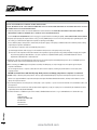
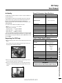
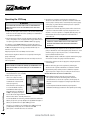
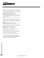
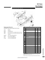
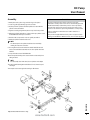
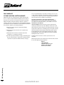
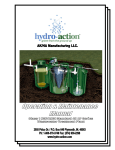
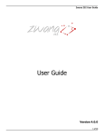
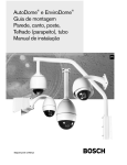
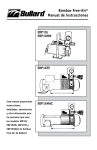
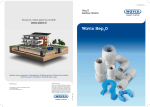
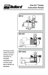
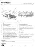
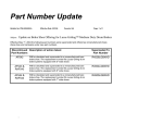
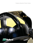
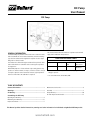
ICE Pump User Manual ICE Pump GENERAL INFORMATION The Bullard ICE pump transfers ambient air from a clean air location, where breathable air can be assured at all times, to workers wearing Type C or CE continuous flow supplied air respirator hoods or tight fitting half- or full-face masks. The ambient air is filtered through a medium efficiency inlet air filter and an inline 90 micron outlet filter before entering the respirator’s air supply hose. Bullard ICE pumps are oil-less and have reciprocating pistons. They produce no carbon monoxide, oil vapors, oil mist or moisture. They do not require expensive carbon monoxide monitors, high temperature alarms or airline filters. No calibration is required. The chart below describes the number of respirators each unit will supply and its maximum outlet pressure. PUMP SPECIFICATION TABLE Maximum Number of Respirators Pump Model No. Hood Style Full or HalfMask Maximum Air Pressure* ICE PUMP One One Approx. 60 psig (400 kPa)** * Not recommended for respirator assemblies requiring a minimum of 60 psig to operate. **To convert kPa to bar, divide kPa by 100 TABLE OF CONTENTS General Information.......................................................................1 Maintenance Service Kits.....................................................................8 Warnings.............................................................................................2 Assembly..............................................................................................9 Air Quality..........................................................................................3 Pump Warranty...................................................................................10 Assembling the ICE Pump Operating the ICE Pump.......................................................................4 Air Filter Replacement Schedule....................................................... 11 Maintaining the ICE Pump................................................................ 5-6 Replacement Parts................................................................................7 This Manual provides detailed instructions, warnings and other information for individuals using Bullard ICE Pump model. www.bullard.com � WARNING READ ALL INSTRUCTIONS IN THIS MANUAL BEFORE USING ICE PUMP. FAILURE TO OPERATE ANY OF THESE PUMPS IN ACCORDANCE WITH THE INSTRUCTIONS CONTAINED IN THIS MANUAL MAY RESULT IN DEATH OR SERIOUS INJURY TO THE RESPIRATOR WEARER. 1. Locate the pump’s inlet air filter in a clean breathable air location at all times. THE PUMP DOES NOT REMOVE TOXIC GASES OR OTHER CONTAMINANTS FROM THE INCOMING AIR IT TRANSFERS TO THE RESPIRATOR WEARER. See the AIR QUALITY REQUIREMENTS section on page 3 for specific details on breathing air quality. THESE PUMPS DO NOT SUPPLY OXYGEN. 2. This pump will only supply the required volume of air [6-15 cfm (170-425 lpm) for hoods or 4-15 cfm (113-425 lpm) for tight fitting half- or fullface masks] to continuous flow supplied air respirators requiring less than 60psi. Be sure that the pump’s outlet pressure, measured by the pressure gauge on the pump, is maintained above the minimum pressure setting required by the respirator manufacturer. To be assured your respirator can be used with this pump refer to: a) The Pump Specification Table on page 1 for the maximum outlet pressure of the pump model you are using. b) The section in the respirator’s instruction manual for the respirator’s approved pressure range and permissible air supply hose lengths. If you have any questions about whether or not your respirator is compatible with this pump, contact Bullard Customer Service Department at 877-285-5273 or 1-859-234-6616. 3. Supplied air respirators used with this pump must not be worn in any atmosphere Immediately Dangerous to Life or Health (IDLH) or from which the wearer cannot escape without the use of the respirator. 4. When connecting your NIOSH approved respirator assembly to the ICE pump, use only air supply hose and couplers approved by the respirator manufacturer. Use of non-approved hose or couplers could reduce the air flow to the respirator, resulting in possible death or serious injury to the respirator wearer. DO NOT use shutoff hoses with the ICE pump. Back pressure can damage pump when no respirator is connected. 5. DO NOT modify or alter this pump in any manner. Use only approved Bullard ICE pump components and replacement parts on the pump. Failure to use approved Bullard components and replacement parts invalidates all Bullard warranties, and may result in death or serious injury to the respirator wearer. 6. If you have any questions concerning the use of this pump or your respirator, or you are not sure the inlet filter is in a breathable location, ask your supervisor. All instructions for the use and care of this product must be supplied to you by your employer as recommended by the manufacturer and as required by Federal Law (29 CFR 1910.134). For technical assistance or additional copies of this manual, call Bullard Customer Service or go to www.Bullard.com to download a copy. Warnings Bullard 1898 Safety Way Cynthiana, KY 41031-9303 877-285-5273 859-234-6611 www.bullard.com 2 www.bullard.com ICE Pump User Manual Air Quality Pump Performance Specifications: The ICE pump’s inlet filters must be located in a clean breathable air location at all times. The breathable air drawn into the inlet filter must meet at least the requirements for Type 1 gaseous air described in the Compressed Gas Association Commodity Specifications G-7.1 (Grade D or higher), as specified by Federal Law 42CFR, Part 84, Subpart b, and 29CFR1910.134(i). The requirements of Grade D breathable air include: *Oxygen.................................... 19.5 - 23.0 % *Hydrocarbons (condensed) in mg/m3 of gas.............5 mg/m3 maximum *Carbon Monoxide.............10 ppm maximum *Carbon Dioxide...........1,000 ppm maximum *No toxic contaminants at levels which would make the air unsafe to breathe. Refer to the C.G.A. Commodity Specification G-7.1 for complete details. It is available from: Compressed Gas Association, 500 Fifth Ave., New York, NY 10036. Unpacking the ICE Pump ICE Pump Reciprocating Pistons PUMP DESIGN: MAXIMUM PRESSURE: TOTAL AIR FLOW: Approx. 60 psig (400 kPa) 8 cfm @ 60 psig (225 lpm @ 400 kPa) INLET FILTERS: (4) Medium Efficiency OUTLET FILTER: Inline 90 micron DIMENSIONS: Width: 18+ inches (45.7 cm) Length: 28 inches (71.1 cm) Height: 20.5 inches (52.1 cm) WEIGHT: (Pump Only) 100 lbs. (approx.) (45.4 kg) SHIPPING WEIGHT: 185 lbs. (83.9 kg) Electric Motor Specifications: 1. Open the shipping carton and remove the ICE pump from the wood frame. We recommend storing the shipping pallet and case in the event the pump must be shipped in the future. ICE Pump Open, Drip-proof Meets UL Requirements CSA Approved ENCLOSURE: CLASS: H.P. Figure 1 2.0 PHASE: Single CYCLES: 60 Hz VOLTS: 115 AMPS: 19Amps @ 115 V. SERVICE FACTOR: 2. Check to insure that the ICE pump has no visible damage. There is no other assembly required for the ICE pump. 3. Check to be sure that the inlet filters, pressure gauge and outlet couplings are all assembled tightly to the pump so that no air can escape. PROTECTOR: 1.25 Internal Thermal Overload � WARNING PROPER MOTOR SELECTION AND WIRING (IN ACCORDANCE WITH LOCAL AND NATIONAL ELECTRIC CODES) IS THE RESPONSIBILITY OF THE USER. Unpacking the ICE Pump/Electric Motor Specifications Natl. Elec. Code: Class B Design N Code K Figure 2 www.bullard.com 3 Operating the ICE Pump � WARNING THE RESPIRATOR USER MUST NOT ENTER THE CONTAMINATED WORK AREA UNTIL ALL OF THE FOLLOWING STEPS HAVE BEEN COMPLETED. 5. A ssemble your respirator by following the manufacturer’s directions as described in the respirator’s instruction manual. Be sure the pump’s outlet pressure, measured by the pressure gauge on the pump, is greater than the minimum pressure required to operate the respirator assembly. The respirator’s minimum approved pressure will be found in the respirator’s instruction manual. If you have any questions as to whether or not your respirator is compatible with this pump, call Bullard’s Customer Service Department at 877-285-5273 or 1-859‑234-6616. 1.Analyze the atmosphere at the location of the air inlet and the pump itself to be sure the pump will not be operating in a contaminated or an explosive atmosphere. 2.Plug the pump into a 115 volt electrical outlet that is wired for 20 amp service. The pump’s motor is equipped with a toggle switch and a 6 foot (1.8 m) grounded cord with a NEMA 5-20 three-prong plug. For extension cords, 10 AWG (20 amps) or heavier duty gauge is recommended. Bullard also recommends that the distance be limited to 100 feet, the plug be three-prong grounded, and that only one extension cord be used. Plug the pump into a 115 volt, 20 amp electrical outlet. Avoid excessive lengths of extension cord, especially if running the pump continuously. The pump’s motor is equipped with a thermal overload protection for 115 volt operation. � WARNING PROPER MOTOR SELECTION AND WIRING (IN ACCORDANCE WITH LOCAL AND NATIONAL ELECTRIC CODES) IS THE RESPONSIBILITY OF THE USER. 3. Each pump will operate sitting inside its Protection Frame with wheels attached for ease of mobility. Operating the ICE Pump 4. Make sure the pump’s inlet filters are located in a clean, uncontaminated location where breathable air is assured at all times (see Figure 3). 4 If the inlet filter cannot be placed in a clean breathable location, install Bullard’s 50 foot (15 m) Inlet Extension Hose Kit (Cat. No. V50IN) to the pump’s inlet ports. See the directions shipped with the Extension Hose Kit for assembly instructions. � WARNING DO NOT USE SHUTOFF HOSES WITH THE ICE PUMP. BACK PRESSURE CAN DAMAGE PUMP WHEN NO RESPIRATOR IS CONNECTED. 6. Before connecting your respirator to the air supply hose, turn the pump on. Allow the air to flow through the pump and hose for a few minutes to purge or expel any hose odors or moisture that may have accumulated inside the hose. TIP: If pump is turned on without a respirator attached, the gauge will read zero because the gauge reads back pressure. 7.Connect the respirator to the air supply hose using the quick dis- connect fittings. 8. With the air flowing, put on the respirator by following the directions in the respirator manufacturer’s instruction manual. 9. Check that the pump’s outlet pressure is within the respirator approved pressure range before proceeding into the work area. YOU ARE NOW READY TO ENTER THE WORK AREA. 10. When finished working, leave the work area wearing the respirator with the air still flowing. Once outside the contaminated area, remove the respirator, turn the pump off, then disconnect the air supply hose using the quick disconnect couplers. See the respirator’s instruction manual for proper inspection, maintenance and storage procedures for the respirator you are using. Figure 3 If clean breathable air cannot be guaranteed at all times within this 50 foot (15 m) reach, you may add up to five (5) additional lengths of 50 foot (15 m) Extension Hose (Cat. V50EX), per inlet. Therefore, you may place your inlet filters up to 300 feet (91.4 m) (6 x 50) away from the pump. Do not add more than 300 (91.4 m) feet of inlet extension hose to each inlet. www.bullard.com ICE Pump User Manual Maintenance and Inspection SYMPTOM: Pump Fails to Start or Hums If pump or motor show evidence of overheating, or is excessively noisy, stop immediately for repairs. Regular inspection can prevent unnecessary damage and repairs. The rider thickness can be an indication of when rings need replacing. If a rider ring measures .055” or less in thickness, a change of all rings should be made. For a unit operated at sea level in fairly clean air at an ambient of 65-75ºF relative humidity of approximately 35%, and at maximum advertised duties, it is suggested that 4,000 hours of operation be used as an initial inspection point. As operating conditions on your particular application improve or worsen, your own experience can be used to determine whether this 4,000 hour figure can be lengthened or should be shortened. Filter Inspection and Replacement The inlet filters and outlet filters require periodic inspection and replacement. Initial inspection is suggested at 500 hours. Then, the user should determine the frequency. Most problems can be prevented by keeping filters clean. Dirty filters decrease pump performance and can decrease pump service life. Make sure the pump is turned off and isolated from the power supply and all pressure and vacuum is released from the pump. Remove inlet filter cover and inspect filter felt. If the felt is completely covered with contamination or has indicated an increase in differential pressure, it must be replaced. Replace felt and install filter cover. Before putting the pump back into service, ensure that any external accessories such as relief valves and gauges have not been damaged. NOTE NEVER LUBRICATE THIS OIL-LESS PUMP. THE MOTOR BEARINGS ARE GREASE PACKED AND SEALED. THEY REQUIRE NO FURTHER LUBRICATION. ICE Pump Trouble Shooting Guide If your Bullard ICE pump is not working satisfactorily, please follow the trouble shooting steps below: Initial Checklist 3. If using a Bullard cool tube, only the FRIGTRON2000 is approved for the ICE pump. The AC1000 may also be used only when combined with the Bullard Spectrum full facepiece, V10 hose, and a V15FT 1/4" Quick Disconnect coupler. 2.Check for the correct electrical current as shown on the motor plate and in the Electric Motor Specification Chart on page 3 of this manual. 3.The pump is equipped with a thermal overload protector that turns the current off when subjected to electrical overloads. Check to be sure that the circuit is not overloaded by the pump and other electrical equipment. 4.Check to make sure that the pistons move freely. If not, service kit for piston rings may be necessary. 5.Wait 15 minutes and restart. SYMPTOM: Outlet Air Pressure Too Low 1. Be sure you know the proper pressure range for the respirator - see the respirator’s instruction manual. 2. Be sure the respirator and air supply hose are connected when the gauge reading is taken. 3. Check to see that the gauge is functioning properly. Replace the gauge if broken or malfunctioning. 4. Check for blockage of 90 micron inline outlet filter. 5. Check to see that no air is escaping from the relief valve on pump. 6. Check that both the inlet filters (Cat. No. 23611 ) and outlet filter (Cat. No. ICEOF) are clean and replace if necessary. Dirty filters restrict air flow. 7. Make sure there is nothing obstructing the airline supply hose. SYMPTOM: Outlet Pressure Too High 1. Ensure there isn’t added back pressure on the ICE pump - high pressure on the outlet pump gauge will occur. Be sure the outlet pressure remains in the proper range for the respirator as specified by the respirator manufacturer. See the respirator’s instruction manual. 2. Check the respirator’s air supply hose for kinks. 3. Ensure that breathing air supply hose is not a shutoff. Back pressure can damage pump when no respirator is connected. SYMPTOM: Pump Overheating 1. 160° - 200°F (80° - 120°C) is normal output air temperature when the pump is continuously running. This heat is dissipated as it travels through the respirator’s air supply hose until it reaches ambient air temperature. 2. Make sure that both the inlet and outlet filters are clean. Replace if necessary. 3. Be sure the outlet pressure remains in the proper range for the respirator as specified by the respirator manufacturer - see the respirator’s instruction manual. 4. The electrical circuit to which the pump is connected is overloaded. Check the amperage load of the circuit and disconnect other electrical equipment, if necessary, from that circuit. 5. Ensure that breathing air supply hose is not a shutoff. Back pressure can damage pump when no respirator is connected. www.bullard.com Maintenance and Inspection 1.You must use at least 100 feet of air supply hose for ICE Pumps, per your respirator’s approved assembly. Any shorter length of hose could cause back pressure and low air flow to user. 2.If using an extension cord, Bullard recommends 20 amp, 3-wire, 10 AWG grounded extension cord up to 100 feet. Do not overload the circuit with additional electrical equipment. The ICE pump requires at least a 12 kw generator. 1.Turn pump switch off and disconnect from the power source. 5 TIP: If ambient air temperatures are high, place the Bullard ICE Pump in the shade. Do not lay airline hoses directly on blacktop. Also, be sure respirator assembly is approved for use with ambient air pumps at pressures less than 60 psig. SYMPTOM: Outlet Air Temperature Too Warm 1.Be sure that at least the first 50 feet (15 m) of air supply hose closest to the pump is laid out (not coiled) to permit excess heat to dissipate from the hose. 2.Keep the air supply hose out of direct sunlight and off warm or hot surfaces. 3.Put a coiled section of the air supply hose in the bottom of a large container. Fill the container with water and ice and cover with a lid. For best results, locate the container as close to the worker as possible. SYMPTOM: Outlet Air Temperature Too Cold 1.Let the pump warm up approximately 15 minutes before using. 2.Coil the first 25-50 feet (7.6-15 m) of air supply hose closest to the pump. 3.Keep the air supply hose off cold surfaces. SYMPTOM: Moisture in Air Supply Hose Line 1.Locate the air inlet filter in a dry, clean air location, where breathable air can be assured at all times. 2.With the air supply hose connected to the pump, but not the respirator, turn the pump on and let it run for approximately 15 minutes to purge the hose of excessive moisture. 3.Between uses, hang the hoses so extra moisture may drain. Maintenance and Inspection IF THESE STEPS FAIL TO RESOLVE THE PROBLEM, CONTACT YOUR BULLARD DISTRIBUTOR OR BULLARD CUSTOMER SERVICE DEPARTMENT AT 877-285-5273 OR 859-234-6616. 6 www.bullard.com ICE Pump User Manual Replacement Parts List 8HDM SERIES REPLACEMENT PARTS AND ACCESSORIES FOR ICE PUMP REF DESCRIPTION QTY 8HDM Cat. No. 1 INLET FILTER ASSEMBLY 4 23611 2 FELT 2 4 B344A 3 SAFETY VALVE 1 AS100F 4 CYLINDER HEAD 4/2 ** AF507 Description 23611 Inlet Filter ICEOF Inline Outlet Filter V50INRemote Inlet Air Hose Kit, 50 Feet (15 m) 1 per inlet V50EXRemote Extension Hose Kit, 50 Feet (15 m) 5 per inlet maximum ICESK11Service Kit for ICE Pump Rebuild ICEPG Pressure Gauge, 0-100 psig V15FT 1/4" Flow Through QD Coupler S16481 1/2" Flow Through QD Coupler 5 HEAD GASKET 4/2 ** AF520A 6 OUTLET VALVE 4/2 ** AF545 7 PLATE VALVE 4/2 ** AF543 8 INLET VALVE 4/2 ** AF544 9 CYLINDER GASKET 4/2 ** AF521 10 CYLINDER 4/2 ** AF509 PISTON RING 8/4 ** AF541 PISTON SEAL 8/4 ** AF540 13 PISTON ROD ASSEMBLY 4/2 ** AF561M 14 RIDER RING 4/2 ** AF595 15 MANIFOLD 1 AF659 16 SQUARE KEY 2/1 ** AB136F 17 FAN/FAN ASSEMBLY-CCW 1 AF748 18 FAN ASSEMBLY-CW 1 AF747 19 SHROUD 2/1 ** AF656 20 MANIFOLD SLEEVE 5 AF567A 22 MANIFOLD 2/1 ** AF550A *** SERVICE KIT 1 ICESK11 *** Item not shown. Denotes parts included in the Service Kit. Parts listed are for stock models. For specific OEM models, please consult the factory. When corresponding or ordering parts, please give complete model and serial numbers. www.bullard.com Replacement Parts 11 12 7 Maintenance & Kit Installation for ICE Pump Service Kit Installation Pump Disassembly NOTE Bullard will not guarantee the performance of a field rebuilt pump. You can return the pump to a Bullard Authorized Service facility, or perform the rebuild procedures described. Kits contain most or all of the following: Head Gasket, Valves, Cylinder Gasket, Piston Ring, Piston Seal, Rider Ring, and Felts. Kits are used for several models and may contain extra parts not applicable for your specific model. Refer to exploded view. � WARNING Disconnect electrical power supply cord before performing maintenance on this product. Some motors are thermally protected and will automatically restart when protector resets. If product is hard wired into system, disconnect electrical power at the circuit breaker or fuse box before performing maintenance on this product. Failure to follow these instructions can result in death, fire or electrical shock. If the product is supplied with an electric power cord, protect it from twisting, cuts and abrasion. When not in use, store in a clean dry place. 1.Disconnect the pump from the electrical power. You must disconnect the pump from electrical power before servicing. 2. Vent all airlines to the pump to remove pressure. You must vent all airlines to the pump to remove pressure before servicing. Do not remove the filters from the cylinder head as metal chips could be dislodged and enter the unit. -Remove the shroud, cylinder head, and valve components. DO NOT rearrange the valve components. -Remove the cylinder and rings. Make sure all parts are clean before reassembling. DO NOT use any chlorinated solvents to clean valves, or any liquids to flush units. THE STAINLESS STEEL VALVES MAY BE CLEANED WITH WATER. All parts, except the valves can be cleaned. � WARNING Maintenance and Kit Installation This product must be properly grounded. Do not modify the plug provided. If it will not fit the outlet, have the proper outlet installed by a qualified electrician. If repair or replacement of the cord or plug is necessary, do not connect the grounding wire to either flat blade terminal. The wire with insulation that is green or green with yellow stripes is the grounding wire. Check the condition of the power supply wiring. Do not permanently connect this product to wiring that is not in good condition or is inadequate for the requirements of this product. Failure to follow these instructions can result in death, fire or electrical shock. 8 www.bullard.com ICE Pump User Manual Assembly � WARNING 1.Install piston seals, piston rings, and rider rings on the piston. 2.Locate ring joints approximately opposite each other. 3.Position piston into cylinder and attach cylinder to bracket with the cylinder screws and washers. 4.Tighten screws finger tight. Move pistons to top dead center position. 5.Adjust each cylinder flush with top of piston and torque cylinder screws to 150-160 inch lbs. Retorque second time. 6.Stack the valve components in order as orginally assembled. 7.Install the cylinder head and head screws. Disconnect electrical power supply cord before performing maintenance on this product. Some motors are thermally protected and will automatically restart when protector resets. If product is hard wired into system, disconnect electrical power at the circuit breaker or fuse box before performing maintenance on this product. Failure to follow these instructions can result in death, fire or electrical shock. If the product is supplied with an electric power cord, protect it from twisting, cuts and abrasion. When not in use, store in a clean dry place. NOTE: The exhaust ports in the cylinder heads have been marked by omitting the ends of two of the fins. 8.Do not tighten heads screws at this time. Install manifold nuts and seals on the manifold and assemble into the other cylinder head and manifold. 9.Torque all head screws to 150-160 inch lbs. 10.Turn fan by hand at this point to ensure that the rod assembly is not hitting the head. NOTE: If rod assembly does hit the head, loosen cylinders and readjust. 11.Position manifold and tighten manifold nut 1/2 to 3/4 turns beyond hand tight. 12.Retorque head screws again after running for 10 minutes. Assembly Exploded view shown for reference only. www.bullard.com 9 PUMP WARRANTY ICE PUMP ONE YEAR LIMITED WARRANTY Bullard warrants to the original purchaser that the ICE pump will be free of defects in material and workmanship under normal use and service for a period of one (1) year from the date of purchase. Bullard’s obligation under this warranty is limited to repairing or replacing, as its option, articles that are returned within the warranty period and that are, after examination, shown to Bullard’s satisfaction to be defective, subject to the following limitations: a) ICE pump must be returned to Bullard with shipping charges prepaid. b) ICE pump must not be altered from its original factory configuration. c) ICE pump must not have been misused, subjected to negligent use, or damaged in transport. d) The date of purchase is within the one (1) year warranty period. (A copy of the purchaser’s original invoice showing the date of purchase is required to validate warranty coverage). In no event shall Bullard be responsible for damages for loss of use or other indirect, incidental, consequential or special costs, expenses or damages incurred by the purchaser, notwithstanding that Bullard has been advised of the possibility of such damages. ANY IMPLIED WARRANTIES, INCLUDING WARRANTIES OF MERCHANTABILITY AND FITNESS FOR A PARTICULAR PURPOSE, ARE LIMITED IN DURATION TO ONE (1) YEAR FROM THE DATE OF PURCHASE OF THIS PRODUCT. TO RETURN GOODS: Written permission must be obtained before returning any material for any reason. Material returned for credit will be subjected to factory inspection. In-warranty product of current design, will be subjected to a rehandling charge less freight originally allowed. All material must be shipped with transportation charges prepaid. Bullard will issue a Return Material Authorization number and shipping label, which must be affixed to all returns to facilitate handling and reduce risk of loss. Products which are obsolete or made to special order are not returnable. Warranty information can be obtained from, defective articles should be sent, and shipping charges prepaid to: ICE Pump Warranty Bullard 1898 Safety Way Cynthiana, KY 41031-9303 Toll-Free: 877-285-5273 Phone: 859-234-6616 10 www.bullard.com ICE Pump User Manual Air Filter Replacement Schedule Regular inspection and replacement of the air filters will prevent extensive and costly pump repair. Dirty or clogged filters can be responsible for failure of the pump to build up outlet pressure and eventual overheating. -Replace the 90 micron inline outlet filter (Cat. No. ICEOF) at least once every 500 running hours or sooner if necessary. The inlet filter keeps moisture as well as particulates out of the air supply. We recommend the following chart be used to monitor and maintain a routine air filter replacement schedule. -Replace the medium efficiency inlet filter (Cat. No. 23611) at least once every 500 running hours or sooner if necessary. 90 MICRON INLINE OUTLET FILTER (Cat. No. ICEOF) Cumulative Pump Operating Hours 500 1,000 1,500 2,000 2,500 3,000 3,500 4,000 4,500 5,000 Last Filter Replacement Date Employee Responsible (Initial) MEDIUM EFFICIENCY INLET FILTER (Cat. No. 23611) Cumulative Pump Operating Hours 500 1,000 1,500 2,000 2,500 3,000 3,500 4,000 4,500 5,000 Last Filter Replacement Date Employee Responsible (Initial) Air Filter Replacement Schedule www.bullard.com 11 Americas: Bullard 1898 Safety Way Cynthiana, KY 41031-9303 • USA Toll-free within USA: 877-BULLARD (285-5273) Tel: +1-859-234-6616 Fax: +1-859-234-8987 Europe: Bullard GmbH Lilienthalstrasse 12 53424 Remagen • Germany Tel: +49-2642 999980 Fax: +49-2642 9999829 Asia-Pacific: Bullard Asia Pacific Pte. Ltd. LHK Building 701, Sims Drive, #04-03 Singapore 387383 Tel: +65-6745-0556 Fax: +65-6745-5176 www.bullard.com ISO 9001 certified ©2015 Bullard. All rights reserved. 60950010749B (0815)