1
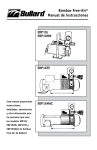
Free-Air® Pumps Instruction Manual EDP10 EDP16TE This Manual provides detailed instructions, warnings and other information for individuals using Bullard FreeAir Pump models EDP10, EDP16TE and EDP16HAZA EDP16HAZ TABLE OF CONTENTS GENERAL INFORMATION . ......................................................................................................... 1 WARNINGS ............................................................................................................................ 2, 3 BREATHING AIR REQUIREMENTS ............................................................................................. 4 ASSEMBLING THE FREE-AIR PUMP Model EDP10 . ............................................................................................................ Model EDP16TE . ........................................................................................................ Model EDP16HAZ . ..................................................................................................... Pump Performance Specifications ............................................................................ Electric Motor Specifications . ................................................................................... 5 5 5 6 7 OPERATING THE FREE-AIR ® PUMP . .......................................................................... 8, 9, 10, 11 MAINTAINING THE FREE-AIR PUMP ...................................................................................... 12 FREE-AIR PUMP TROUBLE SHOOTING GUIDE ................................................................... 13, 14 REPLACEMENT PARTS ............................................................................................................. 15 PUMP WARRANTY ................................................................................................................... 17 AIR FILTER REPLACEMENT SCHEDULE ................................................................................... 18 Free-Air® Pumps Instruction Manual GENERAL INFORMATION Bullard Free-Air ® pumps transfer ambient air from a clean air location, where breathable air can be assured at all times, to workers wearing Type C or CE continuous- flow supplied-air respirator hoods or tight fitting half or full face masks. The ambient air is filtered through a medium efficiency inlet air filter and a Carbofine outlet filter before entering the respirator’s air supply hose. Bullard Free-Air pumps are oil-less and have rotary carbon vanes. They produce no carbon monoxide, oil vapors, oil mist or moisture. They do not require expensive carbon monoxide monitors, high temperature alarms or airline filters. No calibration is required. The pumps will supply air to one, two or three workers depending on the pump model and style of respirator(s) being used. The chart below describes the pump model, the number of respirators each unit will supply and its maximum outlet pressure. PUMP SPECIFICATION TABLE Maximum Number of Respirators Pump Model No. Hood Style Full or Half-Mask Maximum Outlet Air Pressure* EDP10 One Two 15 psig (103 kPa)** EDP16TE Two Three 15 psig (103 kPa) EDP16HAZ Two Three 15 psig (103 kPa) * USE ONLY SUPPLIED-AIR RESPIRATORS THAT ARE APPROVED BY MSHA/NIOSH TO OPERATE AT LESS THAN 15 PSIG (103 kPa). **To convert kPa to bar, divide kPa by 100 1 � WARNING READ ALL INSTRUCTIONS IN THIS MANUAL BEFORE USING FREE AIR® PUMP MODELS EDP10, EDP-16-TE OR EDP-16-HAZ. FAILURE TO OPERATE ANY OF THESE PUMPS IN ACCORDANCE WITH THE INSTRUCTIONS CONTAINED IN THIS MANUAL MAY RESULT IN DEATH OR SERIOUS INJURY TO THE RESPIRATOR WEARER. 1. Locate the pump’s inlet air filter in a clean breathable air location at all times. The pump DOES NOT remove toxic gases or other contaminants from the incoming air it transfers to the respirator wearer. See the BREATHING AIR REQUIREMENTS section on page 4 for specific details on breathing air quality. THESE PUMPS DO NOT SUPPLY OXYGEN. 2. This pump will only supply the required volume of air [6-15 cfm (170-425 lpm) for hoods or 4-15 cfm (113-425 lpm) for tight fitting half or full face masks] to low pressure continuous-flow supplied-air respirators approved by MSHA/NIOSH to operate at less than 15 psig (103 kPa). Be sure that the pump’s outlet pressure, measured by the pressure gauge on the pump, is maintained above the minimum pressure setting required by the respirator manufacturer. To be assured your respirator can be used with this pump refer to: a) The Pump Specification Table on page 1 for the maximum outlet pressure of the pump model you are using. b) The section in the respirator’s instruction manual for the respirator’s approved pressure range and permissible air supply hose lengths. If you have any questions about whether or not your respirator is compatible with this pump, contact Bullard Customer Service Department at 1-800-827-0423 or 1-859-234-6611. 3. Supplied-air respirators used with this pump must not be worn in any atmosphere immediately dangerous to life or health or from which the wearer cannot escape without the use of the respirator. 2 Free-Air® Pumps Instruction Manual 4. When connecting your respirator to the Free-Air® pump use only the air supply hose and couplers required by the respirator manufacturer and approved by MSHA/NIOSH. Use of non-approved hose or couplers will void the respirator’s MSHA/NIOSH Approval and could reduce the air flow to the respirator, resulting in possible death or serious injury to the respirator wearer. 5. DO NOT modify or alter this pump in any manner. Use only approved Bullard Free-Air pump components and replacement parts on the pump. Failure to use approved Bullard components and replacement parts invalidates all Bullard warranties, and may result in death or serious injury to the respirator wearer. 6. If you have any questions concerning the use of this pump or your respirator, or you are not sure the inlet filter is in a breathable location, ask your supervisor. All instructions for the use and care of this product must be supplied to you by your employer as recommended by the manufacturer and as required by Federal Law (29 CFR 1910.134). For technical assistance or additional copies of this manual, call Bullard Customer Service or go to www.Bullard.com to download a copy. Bullard 1898 Safety Way Cynthiana, KY 41031-9303 1-800-827-0423 859-234-6611 www.bullard.com 3 Air Quality The Free-Air® pump’s inlet filter must be located in a clean breathable air location at all times. The breathable air drawn into the inlet filter must meet at least the requirements for Type 1 gaseous air described in the Compressed Gas Association Commodity Specifications G-7.1 (Grade D or higher), as specified by Federal Law 42CFR, Part 84, Subpart b, and 29CFR1910.134(i). 4 The requirements of Grade D breathable air include: *Oxygen.................................... 19.5 - 23.0 % *Hydrocarbons (condensed) in mg/m3 of gas.............5 mg/m3 maximum *Carbon Monoxide.............10 ppm maximum *Carbon Dioxide...........1,000 ppm maximum *No toxic contaminants at levels which would make the air unsafe to breathe. Refer to the C.G.A. Commodity Specification G-7.1 for complete details. It is available from: Compressed Gas Association, 500 Fifth Ave., New York, NY 10036. Free-Air® Pumps Instruction Manual Assembling the Free-Air® Pump 1. MODEL EDP10: a. Open the shipping carton and remove the top layer of foam from the box. Remove the pump from the carton. We recommend storing the shipping carton and foam in the event the pump must be shipped in the future. Figure 1 b. Remove the pressure gauge from its separate box. Assemble it to the gauge port located on top of the pump’s outlet filter body. The gauge should face outward so that it can be read while setting the pressure adjustment knob (see Figure 1). There is no other assembly required on the EDP10 pump. 2. MODEL EDP16TE OR EDP16HAZ: a. Remove the pump from the shipping carton. We recommend storing the shipping carton and plywood board in the event the pump must be shipped in the future. b. Remove the pressure gauge from its separate box. Assemble it to the gauge port located on top of the pump’s outlet filter body. The gauge should face outward so that it can be read while setting the pressure adjustment knob (see Figure 1). 3. ALL PUMPS: a. Unscrew the pump’s outlet filter jar and check to be sure the outlet filter cartridge is seated firmly into the outlet Figure 2 filter body (see Figure 2). DO NOT OPERATE THIS PUMP WITHOUT AN OUTLET FILTER CARTRIDGE (Cat. No. S17101). Be sure the outlet filter O-ring is installed inside the filter body. b. Screw the filter jar back onto the filter body. Tighten firmly by hand, making sure the jar is seated against the O-ring so that no air can escape. c. Check to be sure that the inlet filter, pressure gauge and outlet couplings are all assembled tightly to the pump so that no air can escape. 5 PUMP PERFORMANCE SPECIFICATIONS EDP10 EDP16TE EDP16HAZ PUMP DESIGN: Rotary Carbon Vane (4 vanes) Rotary Carbon Vane (4 vanes) Rotary Carbon Vane (4 vanes) MAXIMUM PRESSURE: 15 psig (103 kPa) 15 psig (103 kPa) 15 psig (103 kPa) TOTAL AIR FLOW: kPa) 10 cfm @ 5 psig (283 lpm @ 34 kPa) 16 cfm @ 5 psig (453 lpm @ 34 kPa) 16 cfm @ 5 psig (453 lpm @ 34 INLET FILTER: Medium Efficiency Medium Efficiency Medium Efficiency OUTLET FILTER: Carbofine with activated carbon Carbofine with activated carbon Carbofine with activated carbon DIMENSIONS: Width Length Height 8 inches (20.3 cm) 16.3 inches (41.4 cm) 13.5 Inches (34.3 cm) 14 inches (35.5 cm) 28 inches (71.1 cm) 16 inches (40.6 cm) 14 inches (35.5 cm) 28 inches (71.1 cm) 16 inches (40.6 cm) WEIGHT: 49 lbs. (approx.) (22.2 kg) 98 lbs. (approx.) (44.5 kg) 98 lbs. (approx.) (44.5 kg) 6 Free-Air® Pumps Instruction Manual Electric Motor Specifications: EDP10 EDP16TE EDP16HAZ ENCLOSURE: Open, Drip- Totally-Enclosed, proof Fan Cooled Capacitor Start Meets UL Requirements, Meets UL Requirements, CSA Approved CSA Approved Hazardous Duty CLASS: Natl. Elec. Code: Natl. Elec. Code: Class B Class III Design N Division 1 and 2 Code K National Electric Code: Class I, Group D, Div. 1 & 2 Class II, Group F, Div. 1 & 2 Class III, Division 1 & 2 H.P. 3/4 1 1/2 1 1/2 PHASE: Single Single Three CYCLES: 60 Hz 60 Hz 60 Hz VOLTS: 115 115/208/230 (Connected for 115 V.) 230 - 460 AMPS: 10.2 @ 115 V. 17.2 @ 115 V. 8.8 @ 208/230 V. 5.0 @ 230 V. 2.5 @ 460 V. SERVICE FACTOR: 1.15 1.0 PROTECTOR: Internal Thermal Overload Manual Reset Thermal Overload equipped for 115 volt operation. Thermal Overload and Starter/Contactor to be provided by the user. Thermal Overload and Starter/Contactor to be provided by the user if rewired to 208/230 volts. 1.25 Meets UL Requirements, CSA Approved � WARNING PROPER MOTOR SELECTION AND WIRING (IN ACCORDANCE WITH LOCAL AND NATIONAL ELECTRIC CODES) IS THE RESPONSIBILITY OF THE USER. 7 Operating the Free-Air Pump � WARNING THE RESPIRATOR USER MUST NOT ENTER THE CONTAMINATED WORK AREA UNTIL ALL OF THE FOLLOWING STEPS HAVE BEEN COMPLETED 1. Analyze the atmosphere at the location of the air inlet and the pump itself to be sure the pump will not be operating in a contaminated or an explosive atmosphere. 2. If Using an EDP10 Pump: Plug the pump into a 115 volt electrical outlet. The pump’s motor is equipped with a toggle switch and a 7 foot (2 m) ground-ed cord with a standard three-prong plug. You may use up to 100 (30.5 m) feet of 50 amp, 3-wire grounded extension cord to reach your electrical outlet. We recommend using 14 gauge wire. Avoid excess-ive lengths of extension cord, especially if running the pump continuously. If Using an EDP16TE Pump: Plug the pump into a 115 volt electrical outlet. The pump’s motor is equipped with a toggle switch and a 7 (2 m) foot ground-ed cord with a standard three-prong plug. You may use up to 100 (30.5 m) feet of 50 amp, 3-wire grounded extension cord to reach your electrical outlet. We recommend using 12 gauge wire. Avoid excessive lengths of extension cord, especially if running the pump continuously. The pump’s motor is equipped with manual reset thermal overload protection for 115 volt operation. The reset button is located on the side opposite the toggle switch. The EDP16TE may be rewired for 208/230 volt, 60 Hz operation. If rewired to 208/230 a suitable starter/contactor and thermal overload protector must be provided by the user. The conversion work should be performed by a qualified electrician. If Using an EDP16HAZ Pump: The EDP16HAZ must be wired for either 230 or 460 volt, 3-phase, 60 Hz operation. THE USER MUST SUPPLY AN EXPLOSIONPROOF THERMAL OVERLOAD PROTECTOR AND A STARTER/CONTACTOR SWITCH. Proper wiring should be performed by a qualified electrician. REFER TO THE MOTOR NAME PLATE OR JUNCTION BOX COVER FOR PROPER WIRING DIAGRAM. � WARNING PROPER MOTOR SELECTION AND WIRING (IN ACCORDANCE WITH LOCAL AND NATIONAL ELECTRIC CODES) IS THE RESPONSIBILITY OF THE USER. 8 Free-Air® Pumps Instruction Manual 3. Each pump will operate sitting on its four rubber mounts. It does not need to be bolted down. If desired, the pump may be mounted on a wall or ceiling as long as the shaft center line is horizontal. 4. Make sure the pump’s inlet filter is located in a clean, uncontaminated location where breathable air is assured at all times (see Figure 3). If the inlet filter cannot be placed in a clean breathable location, install Bullard’s 50 foot (15 m) Inlet Extension Hose Kit (Cat. No. V50IN) to the pump’s inlet port. See the directions shipped with the Extension Hose Kit for assembly instructions. If clean breathable air cannot be guaranteed at all times within this 50 foot (15 m) reach, you may add up to five (5) additional lengths of 50 foot (15 m) Extension Hose (Cat. V50EX). Therefore, you may place your inlet filter up to 300 feet (91.4 m) (6 x 50) away from the pump. Do not add more than 300 Figure 3 (91.4 m) feet of inlet extension hose to the pump. 5. Assemble your respirator by following the manufacturer’s directions as described in the respirator’s instruction manual. Be sure the pump’s outlet pressure, measured by the pressure gauge on the pump, is greater than the minimum MSHA/NIOSH approved pressure required to operate the respirator. The respirator’s minimum approved pressure will be found in the respirator’s instruction manual and/or on labels attached to the respirator. If you have any questions as to whether or not your respirator is compatible with this pump, call Bullard’s Customer Service Department at 1-800-827-0423 or 1-859‑234-6616. 6. Connect the respirator’s NIOSH approved air supply hose(s) to the quick-disconnect outlet coupler(s) on the pump (see Figure 4). Figure 4 9 A. OUTLET COUPLER SPLITTER ADAPTOR If the respirator’s air supply hose(s) have 1/2” Industrial Interchange quick-disconnect fittings and you want to supply air to one of the following: - TWO Half or Full Face Mask respirators using pump model EDP10 or - THREE Half or Full Face Mask respirators using pump model EDP16TE or EDP16HAZ Connect the following Q.D. coupler splitter adaptor to the pump (see Figure 5): Figure 5 Cat. No. V24 - Double Outlet, One FlowThrough (GREEN) & One Shut-Off (RED). B. CONNECTING AIR SUPPLY HOSE(S) WITHOUT 1/2” QUICK-DISCONNECT FITTINGS If your respirator’s NIOSH approved air supply hose will not attach to the pump’s standard 1/2” Industrial Interchange outlet coupler, (see above) you can adapt your hose’s fitting to the pump by converting the pump’s quickdisconnect outlet to 3/8” Female NPT with the installation of one of the following adaptors (see Figure 6): Figure 6 Cat. No. V22 - Converts SINGLE outlet to DOUBLE 3/8” female NPT pipe thread. Cat. No. V23 - Converts SINGLE outlet to SINGLE 3/8” female NPT pipe thread. A variety of quick-disconnect fittings may be used to connect your air supply hose to the 3/8” female pipe thread. Contact your respirator’s manufacturer for the proper fitting (Hansen, Foster, Snap-Tite, Schrader, etc.) (see Figure 7). Figure 7 10 Free-Air® Pumps Instruction Manual 7. Before connecting your respirator to the air supply hose, turn the pump on. Allow the air to flow through the pump and hose for a few minutes to purge or expel any hose odors or moisture that may have accumulated inside the hose. 11. When finished working, leave the work area wearing the respirator with the air still flowing. Once outside the contaminated area, remove the respirator, turn the pump off, then disconnect the air supply hose using the quick-disconnect couplers. 8. Connect the respirator to the air supply hose using the quick-disconnect fittings. 9. With the air flowing, put on the respirator by following the directions in the respirator manufacturer’s instruction manual. See the respirator’s instruction manual for proper inspection, maintenance and storage procedures for the respirator you are using. 10. Set the pump’s outlet pressure to within the respirator’s approved pressure range by adjusting the pressure adjustment valve located on the outlet filter body. To set the pressure adjustment valve, loosen the lock nut. Once the desired outlet pressure has been obtained, retighten the lock nut firmly by hand to maintain consistent outlet pressure. (see Figure 8). YOU ARE NOW READY TO ENTER THE WORK AREA. Figure 8 11 ® Maintaining the Free-Air Pump Bullard Free-Air pumps consist of an elec-trically driven air pump with four carbon vanes. The vanes self-adjust as they wear and should last from 5,000 to 15,000 hours if properly maintained. For the pump to operate at its optimum performance level, the following routine maintenance procedures must be performed: 1. REPLACE THE INLET AND OUTLET FILTERS REGULARLY � WARNING NEVER USE KEROSENE OR OTHER COMBUSTIBLE LIQUIDS OR VAPORS WITH THIS PUMP. THEIR USE MAY RESULT IN AN EXPLOSION WHICH MAY CAUSE INJURY OR DEATH. Directions for Flushing Pump a. Before flushing, disassemble and remove the following parts from the pump: - Disconnect the respirator’s air supply hose Dirty filters may inhibit air flow to the respirator(s), and cause the motor to overload and decrease vane life. - Remove the pump’s inlet filter - Replace the Carbofine outlet filter cartridge (Cat. No. S17101) at least once every 200 running hours or sooner if necessary. b. With the pump running, pour several ounces of approved safety solvent into the pump’s air inlet port. Repeat the flushing if necessary. - Replace the inlet filter (Cat. No. 23611), at least once every 500 operating hours or sooner if necessary. 2. FLUSH PUMP IF NECESSARY Should excessive dirt, sand, foreign particles, moisture or oil be permitted to enter the pump, the carbon vanes will become sluggish and the pump’s performance will deteriorate. This will result in decreased outlet pressure or failure of the pump to operate. If the pump remains idle in a humid environment for a long period of time, rust film may build up in the pump’s chamber and rotor slots. This will result in decreased outlet pressure or a failure to operate at all. If the above occurs, the pump should be flushed with the following recommended solvent: - Loctite Safety Solvent (Cat. No. S17931) 12 - Remove the pump’s outlet filter jar and outlet filter cartridge � WARNING RUN THE PUMP FOR A SUFFICIENT TIME TO PURGE ALL TRACES OF THE SOLVENT BEFORE REPLACING THE FILTERS, RECONNECTING THE AIR SUPPLY HOSE(S) AND USING THE RESPIRATOR. 3. AVOID RUNNING THE PUMP AT EXCESSIVE PRESSURE Avoid running the Free Air pump above 15 psig (103 kPa) for any length of time. Running the pump above 15 psig (103 kPa) could cause motor damage and will create premature wear of the carbon vanes. NOTE NEVER LUBRICATE THIS OIL-LESS PUMP. THE MOTOR BEARINGS ARE GREASE PACKED AND SEALED. THEY REQUIRE NO FURTHER LUBRICATION. Free-Air® Pumps Instruction Manual Free-Air® Pump Trouble Shooting Guide If your Bullard Free-Air pump is not working satisfactorily, please follow the trouble shooting steps below: SYMPTOM: Pump Fails to Start or Hums 1. Turn pump switch off and disconnect from the power source. 2. Check for the correct electrical current as shown on the motor plate and in the Electric Motor Specification Chart on page 7 of this manual. 3. The pump is equipped with a thermal overload protector that turns the current off when subjected to electrical overloads. Check to be sure that the circuit is not overloaded by the pump and other electrical equipment. 4. Wait 15 minutes and restart. 6. Check that both the inlet filter (Cat. No. 23611) and outlet filter (Cat. No. S17101)are clean and replace if necessary. Dirty filters restrict air flow. 7. Flush the pump with Loctite Safety Solvent (Cat. no. S17931) to remove excessive dirt, sand, particles, moisture or oil in the rotor assembly. See the Maintenance Section on Page 12 of this manual for proper directions on flushing the pump. When the parts are reassembled, attach the respirator and turn the pump on, monitoring the outlet pressure. SYMPTOM: Outlet Pressure Too High 1. The pressure adjustment valve is set too high - reset to a lower pressure. Be sure the outlet pressure remains in the proper range for the respirator as specified by the respirator manufacturer - see the respirator’s instruction manual. SYMPTOM: Outlet Air Pressure Too Low 2. Check the respirator’s air supply hose for kinks. 1. Be sure you know the proper pressure range for the respirator - see the respirator’s instruction manual. 1. 160°-200°F (71°-93°C) is normal output air temperature when the pump is continuously running. This heat is dissipated as it travels through the respirator’s air supply hose until it reaches ambient air temperature. 2. Be sure the respirator and air supply hose are connected when the gauge reading is taken. 3. Check to see that the gauge is functioning properly. Replace the gauge if broken or malfunctioning. 4. Check to see that the outlet filter jar is seated firmly into the filter housing’s O-ring so that no air can escape. Replace the jar and/or O-ring if damaged or worn. 5. Check to see that no air is escaping from the relief valve in the outlet filter body. Reset the pressure adjustment valve if necessary. SYMPTOM: Pump Overheating 2. Make sure that both the inlet and outlet filters are clean. Replace if necessary. 3. The pressure adjustment valve is set too high - reset to a lower pressure. Be sure the outlet pressure remains in the proper range for the respirator as specified by the respirator manufacturer - see the respirator’s instruction manual. 4. Flush the pump with Loctite Safety Solvent (cat. no. S17931) to remove excess dirt, sand, particles, moisture or oil in the rotor assembly. 13 Trouble Shooting Guide continued See the Maintenance Section on page 12 of this manual for proper directions on flushing the pump. When the parts are reassembled, attach the respirator and turn the pump on, monitoring its performance for overheating. 5. The electrical circuit to which the pump is connected is overloaded. Check the amperage load of the circuit and disconnect other electrical equipment, if necessary, from that circuit. SYMPTOM: Outlet Air Temperature Too Warm 1. Be sure that at least the first 50 feet (15 m) of air supply hose closest to the pump is laid out (not coiled) to permit excess heat to dissipate from the hose. 2. Keep the air supply hose out of direct sunlight and off warm or hot surfaces. 3. Put a coiled section of the air supply hose in the bottom of a large container. Fill the container with water and ice and cover with a lid. For best results, locate the container as close to the worker as possible. 14 SYMPTOM: Outlet Air Temperature Too Cold 1. Let the pump warm up approximately 15 minutes before using. 2. Coil the first 25-50 feet (7.6-15 m) of air supply hose closest to the pump. 3. Keep the air supply hose off cold surfaces. SYMPTOM: Moisture In Air Supply Hose Line 1. Locate the air inlet filter in a dry, clean air location, where breathable air can be assured at all times. 2. With the air supply hose connected to the pump, but not the respirator, turn the pump on and let it run for approximately 15 minutes to purge the hose of excessive moisture. IF THESE STEPS FAIL TO RESOLVE THE PROBLEM, CONTACT YOUR BULLARD DISTRIBUTOR OR BULLARD CUSTOMER SERVICE DEPARTMENT AT 1-800-827-0423 OR 859-234-6616. Free-Air® Pumps Instruction Manual Replacement Parts List REPLACEMENT PARTS AND ACCESSORIES FOR EDP10, EDP16TE AND EDP16HAZ FREE-AIR PUMPS Cat. No. Description 23611 244852 263552 S17101 S17931 V22 V23 V24 V50IN V50EX Inlet Filter Outlet Filter Jar Outlet Filter Assembly O-Ring Outlet Filter Cartridge, Carbofine Loctite Safety Solvent, 12 oz. (350 ml) Aerosol Can Quick-Disconnect Coupler Adaptor. Converts pump’s quick-disconnect coupler to DOUBLE 3/8” Female NPT Quick-Disconnect Coupler Adaptor. Converts pump’s quick-disconnect coupler to SINGLE 3/8” Female NPT Quick-Disconnect Coupler Splitter/Adaptor. Converts pump’s Quick-disconnect coupler to DOUBLE 1/2” Industrial Interchange Female Couplers (One FlowThrough, One Shut-Off) Remote Inlet Air Hose Kit, 50 Feet (15 m) 1 per pump Remote Extension Hose Kit, 50 Feet (15 m) 5 per pump maximum 15 EDP10 244852 Outlet Filter Jar 23611 Inlet Filter S19681 Pressure Gauge S7101 Outlet Filter Cartridge S16483 Quick-Disconnect Coupler 263552 O-Ring (not shown) EDP16TE 15921 Service Kit (not shown) 244852 Outlet Filter Jar S17101 Outlet Filter Cartridge 23611 Inlet Filter S19683 Pressure Gauge S16191 QuickDisconnect Coupler (Shutoff) S16481 Quick-Disconnect Coupler (FlowThrough) 263552 O-Ring (not shown) EDP16HAZ S17101 Outlet Filter Cartridge 263552 O-Ring (not shown) 16 244852 Outlet Filter Jar 15922 Service Kit (not shown) 23611 Inlet Filter S19683 Pressure Gauge S16481 QuickDisconnect Coupler (FlowThrough) S16191 Quick-Disconnect Coupler (Shut-Off) 15922 Service Kit (not shown) Free-Air® Pumps Instruction Manual PUMP WARRANTY FREE-AIR® PUMP ONE YEAR LIMITED WARRANTY Bullard warrants to the original purchaser that the Free-Air pump will be free of defects in material and workmanship under normal use and service for a period of one (1) year from the date of purchase. E.D. Bullard Company’s obligation under this warranty is limited to repairing or replacing, at its option, articles that are returned within the warranty period and that are, after examination, shown to E.D. Bullard Company’s satisfaction to be defective, subject to the following limitations: a) Free-Air pump must be returned to the E. D. Bullard Company with shipping charges prepaid. b) Free-Air pump must not be altered from its original factory configuration. c) Free-Air pump must not have been misused, subjected to negligent use, or damaged in transport. d) The date of purchase is within the one year warranty period. (A copy of the purchaser’s original invoice showing the date of purchase is required to validate warranty coverage). In no event shall Bullard be responsible for damages for loss of use or other indirect, incidental, consequential or special costs, expenses or damages incurred by the purchaser, notwithstanding that Bullard has been advised of the possibility of such damages. ANY IMPLIED WARRANTIES, INCLUDING WARRANTIES OF MERCHANTABILITY AND FITNESS FOR A PARTICULAR PURPOSE, ARE LIMITED IN DURATION TO ONE (1) YEAR FROM THE DATE OF PURCHASE OF THIS PRODUCT. TO RETURN GOODS: Written permission must be obtained before returning any material for any reason whatsoever. Material returned for credit will be subjected to factory inspection. In-warranty product of current design, will be subjected to a rehandling charge less freight originally allowed. All material must be shipped with transportation charges prepaid. Bullard will issue a Return Material Authorization number and shipping label which must be affixed to all returns to facilitate handling and reduce risk of loss. Products which are obsolete or made to special order are not returnable. Warranty information can be obtained from, and defective articles should be sent, shipping charges prepaid to: Bullard 1898 Safety Way Cynthiana, KY 41031-9303 Toll-Free: 800-877-BULLARD Phone: 859-234-6616 17 Free-Air® Pumps Instruction Manual Air Filter Replacement Schedule Regular inspection and replacement of the air filters will prevent extensive and costly pump repair. Dirty or clogged filters can be responsible for failure of the pump to build up outlet pressure and eventual overheating. -Replace the Carbofine outlet filter (Cat. No. S17101) at least once every 200 running hours or sooner if necessary. The outlet filter cartridge is multi-layered with 40-micron size particles of activated carbon, a sorbent bed with an exposed carbon surface of more than 15,000 square feet (1,615 sq meters). -Replace the medium efficiency inlet filter (Cat. No. 23611) at least once every 500 running hours or sooner if necessary. The inlet filter keeps moisture as well as particulates out of the air supply and helps protect the pump’s carbon vanes. We recommend the following chart be used to monitor and maintain a routine air filter replacement schedule. CARBOFINE OUTLET FILTER (Cat. No. S17101) Cumulative Pump Operating Hours Last Filter Replacement Date 200 400 600 800 1,000 1,200 1,400 1,600 1,800 2,000 MEDIUM EFFICIENCY INLET FILTER (Cat. No. 23611) Employee Responsible (Initial) Cumulative Pump Operating Hours Last Filter Replacement Date Employee Responsible (Initial) 500 1,000 1,500 2,000 2,500 3,000 3,500 4,000 4,500 5,000 ISO 9001 certified ©2010 Bullard. All rights reserved. Americas: E.D. Bullard Company 1898 Safety Way Cynthiana, KY 41031-9303 Toll free: 877-BULLARD (285-5273) Tel: 859-234-6616 Fax: 859-234-8987 www.bullard.com Europe: Bullard GmbH Lilienthalstrasse 12 53424 Remagen • Germany Tel: +49-2642 999980 Fax : +49-2642 9999829 www.bullardextrem.com 6093500182B (0510) Asia-Pacific: Bullard Asia Pacific Pte. Ltd. LHK Building 701, Sims Drive, #04-03 Singapore 387383 Tel: +65-6745-0556 Fax: +65-6745-5176 www.bullard.com