1
4. Device Features
4.1 Geo-Fence
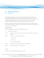
The LT-100 device will support up to 5 circular fences and 5 polygonal fences, Circular fences are
represented with radius and center location. Polygonal fences are represented with vertices. The
maximum vertex supported by LT-100 is 10. Entering or leaving a user geo-fence causes an event or alert
that can be transmitted. Whenever device enters or leaves a “Geo-fence”, the device reports
GEOFENCE_ENTRY or GEOFENCE_EXIT, depending on which direction the fence is crossed.
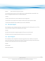
The device also supports one additional circular fence called “System Fence” that is used for Towing
events. System fence will be set automatically when the vehicle is in parking state and disabled after the
vehicle’s ignition has been detected.
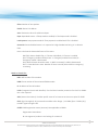
Add Circular Fences
Command: CFENCEADD <ID>,<Delay>,<EVENTS>,<CENTER>,<RADIUS>
ID:
Fence Identifier (0 to 65535)
DELEAY:
Time (in seconds) that a vehicle has to be inside or outside of a fence for an event to be
triggered
EVENTS:
Send events on entry and/or exit from fence
1 - Event on entry
2 - Event on exit
3 – Event on both entry and exit
CENTER:
fence center position Latitude and longitude in degree (float)
RADIUS:
Radius of circular geo-fence in 10meters units
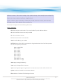
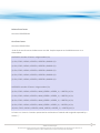
Example:
To add a circular fence at 42.34676,-83.94323 and 1Km radius
16
©2015 Laird Technologies
This document contains proprietary and confidential information of Laird Technologies and shall not be used, disclosed, or
reproduced, in whole or in part, without the prior written consent of Laird Technologies