1
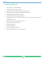
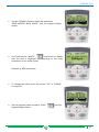
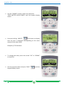
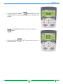
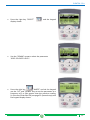
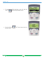
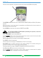
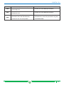
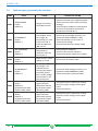
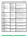
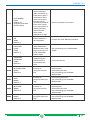
USER GUIDE VARTEK - User Manual ELECTRICAL PANEL FOR CONTROL OF MOTOR WITH FREQUENCY INVERTER - 2 O 3 PUMPS WITH ROTATION - PID CONTROL - ELENTEK S.R.L. II ELENTEK S.R.L. CONTENTS 1. SYMBOLS AND WARNINGS ....................................................................................5 2. GENERAL INFORMATION .......................................................................................6 3. WARNINGS ............................................................................................................7 4. GENERAL DESCRIPTION ..........................................................................................8 5. INSTALLATION........................................................................................................9 6. INVERTER PROGRAMMING .................................................................................. 10 7. 8. 9. 6.1 Motor data programming ................................................................................10 6.2 PID Control Programming .................................................................................18 6.3 Set up of the second pump as duty pump.........................................................27 6.4 Set up of the third pump as duty pump ............................................................27 FAULT TRACING ................................................................................................... 29 7.1 Fault and alarm signals, fault resets and log....................................................29 7.2 Alarm messages generated by the frequency converter ..................................30 7.3 Alarms generated on Base control panel .........................................................33 7.4 Fault messages generated by the converter .....................................................36 GENERAL CONDITIONS ......................................................................................... 42 8.1 Warranty ..........................................................................................................42 8.2 Maintenance.....................................................................................................42 8.3 Disposal ............................................................................................................42 DECLARATION OF CONFORMITY .......................................................................... 43 III ELENTEK S.R.L. IV ELENTEK S.R.L. 1. SYMBOLS AND WARNINGS This operation and maintenance manual uses the symbols outlined below to indicate risks that may arise in the event of failure to observe the instructions supplied. DANGER This symbol corresponds to an immediate risk of death or serious physical injury or material damage. When present, take great care to observe warnings and instructions. This symbol corresponds to a possible risk of death or serious physical injury or material damage. Take care. CAUTION WARNING Failure to observe the instructions in the presence of this symbol may lead to malfunctions and damage to equipment, with possible consequent injuries to the operator. Before performing any work on the electrical panel or system, shut off the electrical power supply. The electrical panel must be connected by a qualified electrician in observance of the relevant electrical standards. Before any other operation, ensure the installation is connected to an efficient earthing system. After making the electrical connection, check that all electrical panel settings are correct to avoid automatic start-up of the electric pump. 5 ELENTEK S.R.L. 2. GENERAL INFORMATION This manual must always accompany the relevant equipment and be conserved in an accessible location for consultation by qualified technicians assigned for operation and maintenance of the system. The installer/user is strongly recommended to carefully read all instructions and information in this manual before using the product, in order to avoid damage or improper use of the unit, which would also render the warranty null and void. Before operating the equipment, carefully read the manual and follow all instructions herein. The information and instructions in this manual refer to the standard use of this product; in the event of special circumstances, functions or applications not described in this document, contact our service centre for assistance. If technical assistance or spare parts are required, when contacting the manufacturer always specify the identification code of the model and construction number as stated on the data plate. Our service centre is available for any requirement or clarification. The electrical equipment supplied must be installed indoors in a well-ventilated environment, within a temperature range of -5° to +40°C. N.B. the information provided in this manual is subject to modifications without notice. The manufacturer shall not be held liable for any damage caused in relation to the use of these instructions as they are to be considered guideline only. Note that failure to observe the instructions provided in this manual may cause physical injury or damage to objects. In any event all local and/or current legislation must be observed at all times. 6 ELENTEK S.R.L. 3. WARNINGS On receipt of the goods, perform an inspection immediately to ensure that the equipment has not been damaged during transport. If defects or missing material are found, the client should promptly notify, and in any event within 5 days of receiving the goods, our retailer, or in the event of direct purchases, the Elentek service centre. The electrical panel must be used exclusively for the purpose and function as specified in design. Any other application or use is to be considered improper and therefore hazardous. All panel installation and maintenance operations must be performed by a specialised technician who is fully aware of the relevant current safety standards. DANGER No parts of the panel must be disassembled without the official authorisation of Elentek: any tampering with or modifications to the unit will render all terms of the warranty null and void. Always disconnect the unit from the power supply before maintenance or cleaning. If the panel is not used for prolonged periods, store the product in a clean and safe location protected against atmospheric agents and the potential risk of dropping/falling. In the event of a fire in the place of installation or the surrounding area, avoid the use of water jets and use the appropriate extinguishing equipment and means (powder, foam, carbon dioxide). DANGER Install the equipment far from heat sources and in a dry and sheltered location in observance of the stated protection rating (IP). The installation of a safety device is recommended to protect the panel power line in compliance with current electrical standards. CAUTION Elentek declines all liability in the event of the following: - Incorrect installation; Use by personnel not adequately trained in the correct use of the panel; Serious failure to perform scheduled maintenance; Use of non-original spare parts or parts not specific to the model; Unauthorised modifications or interventions; Partial or total failure to observe instructions; 7 ELENTEK S.R.L. 4. GENERAL DESCRIPTION Power supply 3 ~ 50/60Hz 400V±10%; • Low voltage control circuits and inputs; • Normally open input for start-up command (manual mode); • Normally open input for minimum level/pressure command; • Analogue input 4-20mA (0-10V on request); • Automatic-0-Manual selector (manual stable); • Frequency Inverter with multifunction LCD display, “PID” control and connection via RS232/485 converter; 8 • Protection of aux. circuits and motor with fuses; • Door lock general disconnect switch; • Forced ventilation kit; • Metal enclosure (IP54); • Ambient temperature: -5/+40 °C; • Relative humidity 50% at 40 °C (condensate free). ELENTEK S.R.L. 5. INSTALLATION Ensure that the mains power supply specifications correspond to the voltage specified on the data plate of the electrical panel and motor connected, then make the earthing connection before all other connections. 1~230V ± 10% 50/60Hz 3~230V ± 10% 50/60Hz 3~400V ± 10% 50/60Hz The power line must be protected by a residual current circuit breaker. Tighten the electrical cables on the relative terminals using a suitable tool correctly sized to avoid the risk of damage to the fixing screws. Take care if using an electric screwdriver. The utility connected must have specifications suitable for use with an inverter. The residual current circuit breaker on the power line must be type “A” (for one-way pulsating current with DC component and AC component) protected against inadvertent surges and option of selecting a trip threshold (recommended at 300mA) and trip delay interval (recommended 0.5 seconds). The installation of an expansion vessel is recommended for precise reading of pre-charged pressure at a value of less than approx. 30% with respect to the system operating pressure, and installed in the immediate vicinity of the pressure sensor. 9 ELENTEK S.R.L. 6. 6.1 INVERTER PROGRAMMING Motor data programming The VARTEK electrical panel has been designed for the control of 1 motor with the aid of an internal programmable inverter in the assistant panel installed on the panel front. Set the selector AUT-0-MAN to “0” and the display shows this setting. Enter the programming menu by pressing “MENU” at the top right of the screen. 10 The keypad display then shows: ELENTEK S.R.L. Press “ENTER” Use the “UP” arrow to select the family “99 START-UP DATA“ and the keypad display shows: Press the right key “SELECT” display shows: and the keypad display shows: and the keypad 11 ELENTEK S.R.L. Use the “DOWN” arrow to select the parameter “9905 MOTOR NOM VOLT“ and the keypad display shows: Press the left key “WRITE” and check on display that the text is displayed corresponding to the exact power supply voltage of the motor (Volt). To change the value, press the arrows “UP” or “DOWN” as required. Set the required value and press “SAVE” keypad display shows: 12 and the ELENTEK S.R.L. Use the “DOWN” arrow to select the parameter “9906 MOTOR NOM CURR“ and the keypad display shows: Press the left key “WRITE” and check on display that the text is displayed corresponding to the exact absorption current of the motor (A). Example of 6 A motor: To change the value, press the arrows “UP” or “DOWN” as required. Set the required value and press “SAVE” display shows: and the 13 ELENTEK S.R.L. Use the “DOWN” arrow to select the parameter “9907 MOTOR NOM FREQ“ and the keypad display shows: Press the left key “SCRIVI” and check on display that the text is displayed corresponding to the exact nominal frequency of the motor (Hz). Example of 50Hz motor: To change the value, press the arrows “UP” or “DOWN” as required. Set the required value and press “SAVE” keypad display shows: 14 and the ELENTEK S.R.L. Use the “DOWN” arrow to select the parameter “9908 MOTOR NOM SPEED“ and the keypad display shows: Press the left key “WRITE” and check on display that the text is displayed corresponding to the exact revolutions of the motor (rpm). Example of 2900 rpm motor: To change the value, press the arrows “UP” or “DOWN” as required. Set the required value and press “SAVE” keypad display shows: and the 15 ELENTEK S.R.L. Use the “DOWN” arrow to select the parameter “9909 MOTOR NOM POWER“ and the keypad display shows: Press the left key “WRITE” and check on display that the text is displayed corresponding to the exact output of the motor (kW). Example of 2.2 kW motor: To change the value, press the arrows “UP” or “DOWN” as required. Set the required value and press “SAVE” keypad display shows: 16 and the ELENTEK S.R.L. Press the left key “EXIT” once to return to the list of families, and the display shows: 17 ELENTEK S.R.L. 6.2 PID Control Programming Use the “DOWN” arrow to select the parameter “40 PROCESS PID SET 1“ and the keypad display shows: Press the right key “SELECT” display shows: Use the “DOWN” arrow to select the parameter “4009 VALUE 100%“: 18 and the keypad ELENTEK S.R.L. Press the right key “SCRIVI” and use the “UP” and “DOWN” keys to modify the parameter according to the maximum range of the pressure sensor (bar). Example: if a 0-10 Bar sensor is used, set the value 10. To save the modified parameter, press the right key “SAVE” . The display returns to the main menu: Use the “DOWN” arrow to select the parameter “4011 INTERNAL SETPNT“: 19 ELENTEK S.R.L. Press the right key “WRITE” and use the “UP” and “DOWN” keys to modify the parameter according to the rated pressure to maintain in the system. Example of pressure at 3.5 bar: To save the modified parameter, press the right key “SAVE” . The display returns to the main menu: Use the “DOWN” arrow to select the parameter “4023 PID SLEEPLEVEL“: 20 ELENTEK S.R.L. Press the right key “WRITE” and use the “UP” and “DOWN” keys to modify the parameter at a frequency of 00.0 Hz. To save the modified parameter, press the right key “SAVE”. Press the left key the main menu: “EXIT” three times to return to 21 ELENTEK S.R.L. Close all utilities to restore pressure to the entire hydraulic circuit. Set the AUT-0-MAN selector to Automatic mode (AUT) and check on the keypad display that the Hz value increases 22 ELENTEK S.R.L. Ensure that the value on display reaches the previously set nominal pressure value (in this case 3.5 bar as set in parameter 4011) and that the display shows: When the nominal pressure is reached and the entire circuit is pressurised, let the pump run for approximately one minute; then check at which frequency the system is stabilised (in this case presumably at 33 Hz). Set the selector AUT-0-MAN to “0” and the display shows this setting: 23 ELENTEK S.R.L. Enter the programming menu by pressing the right key “MENU”. The keypad display then shows: Press the right key “ENTER” display shows: Use the “DOWN” arrow to select the parameter “40 PROCESS PID SET 1“: 24 and the keypad ELENTEK S.R.L. Press the right key “SELECT” display shows: Use the “DOWN” arrow to select the parameter “4023 PID SLEEP LEVEL“: Press the right key “WRITE” and via the keypad use the “UP” and “DOWN” keys to set the parameter to a frequency of 2 or 3Hz greater than the previous reading (in this case 33Hz+3Hz=36) see page 23 (second step) and the keypad display shows: and the keypad 25 ELENTEK S.R.L. To save the modified parameter, press the right key “SAVE” and the keypad display shows: Press the left key the main menu: 26 “EXIT” three times to return to ELENTEK S.R.L. 6.3 Set up of the second pump as duty pump Set the parameter 8109 with the frequency value of stop of the second pump (default 50 Hz) and parameter 8112 with the value of start of the pump. N.B.: The frequency value of stop has to be bigger than the “SLEEP PID” value (parameter 4023). 6.4 Set up of the third pump as duty pump Set the parameter 8109 with the frequency value of stop of the second pump (default 50 Hz) and parameter 8112 with the value of start of the pump. Set the parameter 8110 with the frequency value of stop of the third pump (default 50 Hz) and parameter 8113 with the value of stop of the pump. N.B.: The frequency value of stop has to be bigger than the “SLEEP PID” value (parameter 4023). THE SYSTEM IS NOW READY TO USE. 27 ELENTEK S.R.L. To ensure correct operation, the system must be set to remote mode (REM at the top left). The LOC/REM button enables the user to switch between REMOTE (REM) and LOCAL (LOC) mode as required. When the inverter is set to local mode, all automations are inhibited and the inverter remains on stand-by even when pressure drops. Press LOC/REM once and return the system to REMOTE mode (REM). N.B. CAUTION! RESTORE SETTINGS (before performing this operation, contact the technical office for assistance). Set the “AUT-0-MAN” control selector SA1 to “0”. Use the LOC/REM button on the control panel to switch from remote control to local control mode (the text “LOC” is displayed at the top left of the panel). Enter the MENU and use the arrows to scroll through to “BACKUP PAR”. Press SELECT to select this parameter. Use the arrows to scroll through to “DOWNLOAD ALL TO ACS” on the display. Press SELECT again to confirm and wait for the inverter settings to be restored. (During this procedure the display shows the percentage of settings loaded). The display shows the message “PARAMETER DOWNLOAD OPERATION SUCCESSFUL”. Press OK and then EXIT twice to return to the main menu. Use the LOC/REM button on the panel to return inverter control to remote mode for standard operation.(the text “REM” is displayed at the top left of the display). 28 ELENTEK S.R.L. 7. FAULT TRACING This chapter illustrates the fault finding procedures with solutions, and how to view the fault log. It also lists all alarm and fault messages, with possible causes and corrective actions. WARNING! Maintenance on the frequency converter must be performed exclusively by qualified electricians. Refer to the safety standards outlined in the Safety chapter on page 7 before performing any work on the converter. 7.1 Fault and alarm signals, fault resets and log An alarm or fault message on the panel display indicates abnormal drive status. Using the information given in this chapter most alarm and fault causes can be identified and corrected., contact Elentek S.r.l. for assistance. The drive can be reset either by pressing the keypad key (Basic control panel) or (Assistant control panel), through digital input or fieldbus, or by switching the supply voltage off for a while. The source for the fault reset signal is selected by 302 Fault tracing parameter 1604 FAULT RESET SEL. When the fault has been removed, the motor can be restarted. When a fault is detected, it is stored in the fault history. The latest faults are stored together with the time stamp. Parameters 0401 LAST FAULT, 0412 PREVIOUS FAULT 1 and 0413 PREVIOUS FAULT 2 store the most recent faults. Parameters 0404…0409 show drive operation data at the time the latest fault occurred. The Assistant control panel provides additional information about the fault history. 29 ELENTEK S.R.L. 7.2 Alarm messages generated by the frequency converter CODE ALARM 2001 OVERCURRENT 0308 bit 0 (programmable fault function 1610) 2002 2003 2004 2005 2006 OVERVOLTAGE 0308 bit 1 (programmable fault function 1610) UNDERVOLTAGE 0308 bit 2 (programmable fault function 1610) DIR LOCK 0308 bit 3 IO COMM 0308 bit 4 (programmable fault function 3018, 3019) AI1 LOSS 0308 bit 5 (programmable fault function 3001, 3021) CAUSE CORRECTIVE ACTION Output current limit controller is active. Check motor load. Check acceleration time (2202 and 2205). Check motor and motor cable (including phasing). Check ambient conditions. Load capacity decreases if installation site ambient temperature exceeds 40 °C. DC overvoltage controller is active. Check deceleration time (2203 and 2206). Check input power line for static or transient overvoltage. DC undervoltage controller is active. Check input power supply. Change of direction is not allowed. Check parameter 1003 DIRECTION settings. Fieldbus communication break Check status of fieldbus communication. Check fault function parameter settings. Check connections. Check if master can communicate. Analog input AI1 signal has fallen below limit defined by parameter 3021 AI1 FAULT LIMIT. Analog input AI2 signal has fallen below limit defined by parameter 3022 AI2 FAULT LIMIT. 2007 AI2 LOSS 0308 bit 6 (programmable fault function 3001, 3022) 2008 PANEL LOSS 0308 bit 7 (programmable fault function 3002) Control panel selected as active control location for drive has ceased communicating. 2009 DEVICE OVERTEMP 0308 bit 8 Drive IGBT temperature is excessive. Alarm limit is 120 °C. 30 Check fault function parameter settings. Check for proper analog control signal levels. Check connections. Check fault function parameter settings. Check for proper analog control signal levels. Check connections. Check panel connection. Check fault function parameters. Check control panel connector. Refit control panel in mounting platform. If drive is in external control mode (REM) and is set to accept start/stop, direction commands or references through control panel: Check group 10 START/STOP/DIR and 11 REFERENCE SELECT settings. Check ambient conditions. Check air flow and fan operation. Check motor power against drive power. ELENTEK S.R.L. 2010 2012 2013 2014 MOTOR TEMP 0308 bit 9 (programmable fault function 3005…3009 / 3503) MOTOR STALL 0308 bit 11 (programmable fault function 3010…3012) AUTORESET 0308 bit 12 AUTOCHANGE 0308 bit 13 Motor temperature is too high (or appears to be too high) due to excessive load, insufficient motor power, inadequate cooling or incorrect start-up data. Measured motor temperature has exceeded alarm limit set by parameter 3503 ALARM LIMIT. Motor is operating in stall region due to eg excessive load or insufficient motor power. Automatic reset alarm PFC Autochange function is active. Check motor ratings, load and cooling. Check start-up data. Check fault function parameters. Check value of alarm limit. Check that actual number of sensors corresponds to value set by parameter 3501 SENSOR TYPE. Let motor cool down. Ensure proper motor cooling: Check cooling fan, clean cooling surfaces, etc. Check motor load and drive ratings. Check fault function parameters. Check parameter group 31 AUTOMATIC RESET settings. See parameter group 81 PFC CONTROL. 2015 PFC I LOCK 0308 bit 14 PFC Interlocks are active. Drive cannot start • any motor (when Autochange is used) • the speed regulated motor (when Autochange is not used). See parameter group 81 PFC CONTROL. 2018 PID SLEEP 0309 bit 1 Sleep function has entered sleeping mode. See parameter groups 40 PROCESS PID SET 1… 41 PROCESS PID SET 2. 2021 START ENABLE 1 MISSING 0309 bit 4 No Start enable 1 signal received 2022 START ENABLE 2 MISSING 0309 bit 5 No Start enable 2 signal received EMERGENCY STOP 0309 bit 6 Drive has received emergency stop command and ramps to stop according to ramp time defined by parameter 2208 EMERG DEC TIME. 2023 Check parameter 1608 START ENABLE 1 settings. Check digital input connections. Check fieldbus communication settings. Check parameter 1609 START ENABLE 2 settings. Check digital input connections. Check fieldbus communication settings. Check that it is safe to continue operation. Return emergency stop push button to normal position. 31 ELENTEK S.R.L. 2025 FIRST START 0309 bit 8 2026 INPUT PHASE LOSS 0309 bit 9 (programmable fault function 3016) 2027 USER LOAD CURVE 0309 bit 10 2028 START DELAY 0309 bit 11 2030 INLET LOW 0309 bit 13 2031 OUTLET HIGH 0309 bit 14 2032 OUTLET HIGH 0309 bit 14 Motor identification magnetization is on. This alarm belongs to normal start-up procedure. Intermediate circuit DC voltage is oscillating due to missing input power line phase or blown fuse. Alarm is generated when DC voltage ripple exceeds 14% of nominal DC voltage. Condition defined by 3701 USER LOAD C MODE has been valid longer than half of the time set by 3703 USER LOAD C TIME. Start delay in progress. Pressure at pump/fan inlet too low. Pressure at pump/fan outlet too high Pressure at pump/fan outlet too high 2033 INLET VERY LOW 0310 bit 0 Pressure at pump/fan inlet too low 2034 OUTLET VERY HIGH 0310 bit 1 Pressure at pump/fan outlet too high. 32 Wait until drive indicates that motor identification is completed. Check input power line fuses. Check for input power supply imbalance. Check fault function parameters. See parameter group 37 USER LOAD CURVE. See parameter 2113 START DELAY. Check for a closed valve on the inlet side of the pump/fan. Check piping for leaks. See parameter group 44 PUMP PROTECTION. Check piping for blocks. See parameter group 44 PUMP PROTECTION. See parameters 4421…4426. Check for a closed valve on the inlet side of the pump/fan. Check piping for leaks. See parameter group 44 PUMP PROTECTION. Check piping for blocks. See parameter group 44 PUMP PROTECTION. ELENTEK S.R.L. 7.3 Alarms generated on Base control panel On the Base control panel, the alarms are indicated by the code A5xxx. CODE CAUSE CORRECTIVE ACTION 5001 Drive is not responding. Check panel connection. 5002 Incompatible communication profile. Contact your local ABB representative. 5010 Corrupted panel parameter backup file. 5011 Drive is controlled from another source. Change drive control to the local control mode. 5012 Direction of rotation is locked. Enable change of direction. See parameter 1003 DIRECTION. 5013 Panel control is disabled because start inhibit is active. Start from the panel is not possible. Reset the emergency stop command or remove the 3wire stop command before starting from the panel. 5014 Panel control is disabled because of drive fault. Reset drive fault and retry. 5015 Panel control is disabled because the local control mode lock is active. Retry parameter upload. Retry parameter download. Deactivate the local control mode lock and retry. See parameter 1606 LOCAL LOCK. 5018 Parameter default value is not found. Contact your local ABB representative. 5019 Writing non-zero parameter value is prohibited. Only parameter reset is allowed. 5020 Parameter or parameter group does not exist or parameter value is inconsistent. Contact your local ABB representative. 5021 Parameter or parameter group is hidden. Contact your local ABB representative. 5022 Parameter is write protected. Parameter value is read-only and cannot be changed. 5023 Parameter change is not allowed, when drive is running. Stop drive and change parameter value. 5024 Drive is executing a task. Wait until task is completed. 5025 Software is being uploaded or downloaded. Wait until upload/download is complete. 5026 Value is at or below minimum limit. Contact your local ABB representative. 5027 Value is at or above maximum limit. Contact your local ABB representative. 5028 Invalid value Contact your local ABB representative. 5029 Memory is not ready. Retry. 5030 Invalid request Contact your local ABB representative. 5031 Drive is not ready for operation, eg due to low DC voltage. Check input power supply. 33 ELENTEK S.R.L. CODE CAUSE CORRECTIVE ACTION 5032 Parameter error. Contact your local ABB representative. Parameter download error. 5040 5041 Selected parameter set is not in current parameter backup file. Parameter backup file does not fit into memory. Perform upload function before download. Contact your local ABB representative. Parameter download error. 34 5042 Selected parameter set is not in current parameter backup file. Perform upload function before download. 5044 Parameter backup file restoring error Check that file is compatible with drive. 5050 Parameter upload aborted. Retry parameter upload. 5051 File error. Contact your local ABB representative. 5052 Parameter upload has failed. Retry parameter upload. 5060 Parameter download aborted. Retry parameter download. 5062 Parameter download has failed. Retry parameter download. 5070 Panel backup memory write error. Contact your local ABB representative. 5071 Panel backup memory read error Contact your local ABB representative. 5080 Operation is not allowed because the drive is not in the local control mode. Switch to the local control mode. 5081 Operation is not allowed because of active fault. Check cause of fault and reset fault. 5083 Operation is not allowed because parameter lock is on. Check parameter 1602 PARAMETER LOCK setting. 5084 Operation is not allowed because drive is performing a task. Wait until task is completed and retry. 5085 Parameter download from source to destination drive has failed. Check that source and destination drive types are same, ie ACS310. See the type designation label of the drive. 5086 Parameter download from source to destination drive has failed. Check that source and destination drive type designations are the same. See type designation labels of the drives. 5087 Parameter download from source to destination drive has failed because parameter sets are incompatible. Check that source and destination drive information are same. See parameters in group 33 INFORMATION. 5088 Operation has failed because of drive memory error. Contact your local ABB representative. 5089 Download has failed because of CRC error. Contact your local ABB representative. ELENTEK S.R.L. CODE CAUSE CORRECTIVE ACTION 5090 Download has failed because of data processing error. Contact your local ABB representative. 5091 Operation has failed because of parameter error. Contact your local ABB representative. Parameter download from source to destination drive has failed because Check that source and destination drive information are same. See parameters in group parameter sets are incompatible. 33 INFORMATION. 5092 35 ELENTEK S.R.L. 7.4 CODE 0001 Fault messages generated by the converter FAULT OVERCURRENT (2310) 0305 bit 0 0002 DC OVERVOLT (3210) 0305 bit 1 0003 DEV OVERTEMP (4210) 0305 bit 2 0004 SHORT CIRC (2340) 0305 bit 3 0006 0007 0008 36 DC UNDERVOLT (3220) 0305 bit 5 AI1 LOSS (8110) 0305 bit 6 (programmable fault function 3001, 3021) AI2 LOSS (8110) 0305 bit 7 (programmable fault function 3001, 3022) CAUSE Output current has exceeded trip level. Excessive intermediate circuit DC voltage. DC overvoltage trip limit is 420 V for 200 V drives and 840 V for 400 V drives. Drive IGBT temperature is excessive. Fault trip limit is 135 °C. Short circuit in motor cable(s) or motor. Intermediate circuit DC voltage is not sufficient due to missing input power line phase, blown fuse, rectifier bridge internal fault or too low input power. Analog input AI1 signal has fallen below limit defined by parameter 3021 AI1 FAULT LIMIT. Analog input AI2 signal has fallen below limit defined by parameter 3022 AI2 FAULT LIMIT. CORRECTIVE ACTION Check motor load. Check acceleration time (2202 and 2205). Check motor and motor cable (including phasing). Check ambient conditions. Load capacity decreases if installation site ambient temperature exceeds 40 °C. Check that overvoltage controller is on (parameter 2005 OVERVOLT CTRL). Check input power line for static or transient overvoltage. Check deceleration time (2203, 2206). Check ambient conditions. Check air flow and fan operation. Check motor power against drive power. Check motor and motor cable. Check that undervoltage controller is on (parameter 2006 UNDERVOLT CTRL). Check input power supply and fuses. Check fault function parameter settings. Check for proper analog control signal levels. Check connections. Check fault function parameter settings. Check for proper analog control signal levels. Check connections. ELENTEK S.R.L. 0009 0010 0012 0014 0015 0016 MOT OVERTEMP (4310) 0305 bit 8 (programmable fault function 3005…3009 / 3504) PANEL LOSS (5300) 0305 bit 9 (programmable fault function 3002) MOTOR STALL (7121) 0305 bit 11 (programmable fault function 3010…3012) EXT FAULT 1 (9000) 0305 bit 13 (programmable fault function 3003) EXT FAULT 2 (9001) 0305 bit 14 (programmable fault function 3004) EARTH FAULT (2330) 0305 bit 15 (programmable fault function 3017) Motor temperature is too high (or appears to be too high) due to excessive load, insufficient motor power, inadequate cooling or incorrect start-up data. Measured motor temperature has exceeded fault limit set by parameter 3504 FAULT LIMIT. Control panel selected as active control location for drive has ceased communicating. Check motor ratings, load and cooling. Check start-up data. Check fault function parameters. Check value of fault limit. Check that actual number of sensors corresponds to value set by parameter 3501 SENSOR TYPE. Let motor cool down. Ensure proper motor cooling: Check cooling fan, clean cooling surfaces, etc. Check panel connection. Check fault function parameters. Check control panel connector. Refit control panel in mounting platform. If drive is in external control mode (REM) and is set to accept start/stop, direction commands or references through control panel: Check group 10 START/STOP/DIR and 11 REFERENCE SELECT settings. Motor is operating in stall region due to eg excessive load or insufficient motor power. Check motor load and drive ratings. Check fault function parameters. External fault 1. Check external devices for faults. Check parameter 3003 EXTERNAL FAULT 1 setting. External fault 2. Check external devices for faults. Check parameter 3004 EXTERNAL FAULT 2 setting. Drive has detected earth (ground) fault in motor or motor cable. Check motor. Check motor cable. Motor cable length must not exceed maximum specifications. Note: Disabling earth fault (ground fault) may void the warranty. 37 ELENTEK S.R.L. 0018 THERM FAIL (5210) 0306 bit 1 0021 CURR MEAS (2211) 0306 bit 4 0022 SUPPLY PHASE (3130) 0306 bit 5 0024 OVERSPEED (7310) 0306 bit 7 0026 0027 0028 0029 0030 38 DRIVE ID (5400) 0306 bit 9 CONFIG FILE (630F) 0306 bit 10 SERIAL 1 ERR (7510) 0306 bit 11 (programmable fault function 3018, 3019) EFB CON FILE (6306) 0306 bit 12 FORCE TRIP (FF90) 0306 bit 13 Drive internal fault. Thermistor used for drive internal temperature measurement is open or short circuited. Drive internal fault. Current measurement is out of range. Intermediate circuit DC voltage is oscillating due to missing input power line phase or blown fuse. Trip occurs when DC voltage ripple exceeds 14% of nominal DC voltage. Motor is turning faster than highest allowed speed due to incorrectly set minimum/maximum speed. Operating range limits are set by parameters 2007 MINIMUM FREQ and 2008 MAXIMUM FREQ. Contact your local ABB representative. Contact your local ABB representative. Check input power line fuses. Check for input power supply imbalance. Check fault function parameters. Check minimum/maximum frequency settings. Check adequacy of motor braking torque. Internal drive ID fault. Contact your local ABB representative. Internal configuration file error. Contact your local ABB representative. Fieldbus communication break. Check status of fieldbus communication. Check fault function parameter settings. Check connections. Check if master can communicate. Configuration file reading error. Contact your local ABB representative. Trip command received from fieldbus. See appropriate communication module manual. ELENTEK S.R.L. OUTP WIRING (FF95) 0306 bit 15 (programmable fault function 3023) Incorrect input power and motor cable connection (ie, input power cable is connected to drive motor connection). The fault can be erroneously declared if the drive is faulty or the input power is a delta grounded system and the motor cable capacitance is large. Check input power connections 0036 INCOMPATIBLE SW (630F) 0307 bit 3 Loaded software is not compatible. Contact your local ABB representative. 0038 USER LOAD CURVE (FF6B) 0307 bit 4 0039 UNKNOWN EXTENSION (7086) 0307 bit 5 0040 INLET VERY LOW (8A81) 0307 bit 6 Pressure at pump/fan inlet too low Check for a closed valve on the inlet side of the pump/fan. Check piping for leaks. See parameter group 44 PUMP PROTECTION. 0041 OUTLET VERY HIGH (8A83) 0307 bit 7 Pressure at pump/fan outlet too high Check piping for blocks. See parameter group 44 PUMP PROTECTION. 0042 INLET LOW (8A80) 0307 bit 8 Pressure at pump/fan inlet too low. 0043 OUTLET HIGH (8A82) 0307 bit 9 Pressure at pump/fan outlet too high. 0035 Condition defined by 3701 USER LOAD C MODE has been valid longer than the time set by 3703 USER LOAD C TIME. Option module not supported by the drive firmware is connected to the drive. See parameter group 37 USER LOAD CURVE. Check connections. Check for a closed valve on the inlet side of the pump/fan. Check piping for leaks. See parameter group 44 PUMP PROTECTION. Check piping for blocks. See parameter group 44 PUMP PROTECTION. 39 ELENTEK S.R.L. 1000 PAR HZRPM (6320) 0307 bit 15 Incorrect frequency limit parameter setting 1001 PAR PFC REF NEG (6320) 0307 bit 15 Incorrect PFC parameters 1003 PAR AI SCALE (6320) 0307 bit 15 Incorrect analog input AI signal scaling. 1004 PAR AO SCALE (6320) 0307 bit 15 Incorrect analog output AO signal scaling. 1006 PAR EXT RO (6320) 0307 bit 15 Incorrect extension relay output parameters. 1012 PAR PFC IO 1 (6320) 0307 bit 15 I/O configuration for PFC not complete. 1013 PAR PFC IO 2 (6320) 0307 bit 15 I/O configuration for PFC not complete 40 Check parameter settings. Check that following applies: • 2007 MINIMUM FREQ < 2008 MAXIMUM FREQ • 2007 MINIMUM FREQ / 9907 MOTOR NOM FREQ and 2008 MAXIMUM FREQ / 9907 MOTOR NOM FREQ are within range. Check parameter group 81 PFC CONTROL settings. Check that following applies: • 2007 MINIMUM FREQ > 0 when 8123 is ACTIVE or SPFC ACTIVE. Check parameter group 13 ANALOG INPUTS settings. Check that following applies: • 1301 MINIMUM AI1 < 1302 MAXIMUM AI1 • 1304 MINIMUM AI2 < 1305 MAXIMUM AI2. Check parameter group 15 ANALOG OUTPUTS settings. Check that following applies: • 1504 MINIMUM AO1 < 1505 MAXIMUM AO1. Check parameter settings. Check that following applies: • MREL relay output extension module is connected to the drive. • 1402…1403 RELAY OUTPUT 2 … RELAY OUTPUT 3 and 1410 RELAY OUTPUT 4 have non-zero values. See MREL-01 relay output extension module user's manual (3AUA0000035974 [English]). Check parameter settings. Following must apply: • There are enough relays parameterized for PFC. • No conflict exists between parameter group 14 RELAY OUTPUTS, parameter 8117 NR OF AUX MOT and parameter 8118 AUTOCHNG INTERV. Check parameter settings. Following must apply: • The actual number of PFC motors (parameter 8127 MOTORS) matches the PFC motors in parameter group 14 RELAY OUTPUTS and parameter 8118 AUTOCHNG INTERV. ELENTEK S.R.L. 1014 PAR PFC IO 3 (6320) 0307 bit 15 1015 PAR USER U/F (6320) 0307 bit 15 I/O configuration for PFC not complete. The drive is unable to allocate a digital input (interlock) for each PFC motor. Incorrect voltage to frequency (U/f) ratio voltage setting. See parameters 8120 INTERLOCKS and 8127 MOTORS. Check parameter 2610 USER DEFINED U1…2617 USER DEFINED F4 settings. 1017 PAR SETUP 1 (6320) 0307 bit 15 It is not allowed to use frequency input signal and frequency output signal simultaneously. Disable frequency output or frequency input: • change transistor output to digital mode (value of parameter 1804 TO MODE = DIGITAL), or • change frequency input selection to other value in parameter groups 11 REFERENCE SELECT, 40 PROCESS PID SET 1, 41 PROCESS PID SET 2 and 42 EXT / TRIM PID. 1026 PAR USER LOAD C (6320) 0307 bit 15 Incorrect user load curve parameter setting. Check parameter settings. 41 ELENTEK S.R.L. 8. GENERAL CONDITIONS 8.1 Warranty The product warranty is subject to the general terms of sale of the company Elentek S.r.l. Acknowledgement of the warranty depends on the strict and proven observance of the operating instructions in this booklet and application of the correct mechanical, hydraulic and electro-technical practices. All products are covered by a warranty valid for 12 months, which covers all construction defects of our products and includes the replacement/repairs of defective parts. The warranty will not be deemed valid in the event of: - tampering with the panel (modifications without prior authorisation); faults due to lack of or inadequate protection and/or connection errors; faults caused by exceeding data plate specifications; normal wear and tear; failure by installation personnel to observe the specified operating procedures; accidental causes, natural disasters of any kind, such as fires, flooding, water or lightning; The defective material must be delivered carriage paid to Elentek S.r.l., who reserves the right to final judgement of the cause of the said defects. The Warranty applies exclusively to restoring the original product characteristics and does not cover material damage or physical injury. 8.2 Maintenance The panel does not require routine maintenance provided that it is used within the operating limits and in observance of the instructions in this manual. Special maintenance or repairs must be performed exclusively by authorised service centres. In the event of repairs, only original spare parts must be used. The manufacturer declines all liability for material damage or injury to persons or animals caused by maintenance interventions performed by unauthorised personnel or using non-original materials. 8.3 Disposal In the event of disassembly and scrapping, strictly observe local legislation regarding pollution. Waste disposal according to material categories is recommended. 42 ELENTEK S.R.L. 9. DECLARATION OF CONFORMITY ELENTEK Srl Unipersonale Via A. Meucci, 5/11 35028 Piove di Sacco (PD) ITALY hereby declares, under its sole responsibility, that the machine: Trademark ELENTEK Series VARTEK complies with the provisions of the following EU directives and subsequent amendments: Machinery 2006/42/EC European Directive 2006/95/EC Electromagnetic Compatibility 2004/108/EC and subsequent amendments, in compliance with the following technical standards: EN 61439 EN 61000-3-2 EN 55014-1 EN 61000-3-3 Piove di Sacco, 01.04.2014 LEGAL REPRESENTATIVE Michele Borgato 43 ELENTEK S.R.L. NOTE 44 ELENTEK S.R.L. NOTE 45 ELENTEK S.R.L. NOTE 46 ELENTEK S.R.L. NOTE 47 ELENTEK SRL SOCIETÀ UNIPERSONALE Via A. Meucci 5/11 - 35028 Piove di Sacco (PD) - ITALIA Tel. +39 049 9730367 - Fax +39 049 9731063 www.elentek.com - [email protected] VAT No. 04534630282 Cod. MQ 0011 UK Rev. 00 Em. 04.2014