1
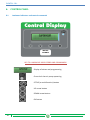
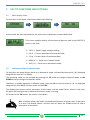
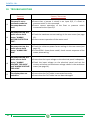
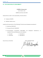
USER GUIDE CONTROL DISPLAY - User Manual DIGITAL CONTROL PANEL ELENTEK S.R.L. II ELENTEK S.R.L. CONTENTS 1. SYMBOLS AND WARNINGS ....................................................................................5 2. GENERAL INFORMATION .......................................................................................6 3. WARNINGS ............................................................................................................7 4. GENERAL DESCRIPTION ..........................................................................................8 5. INSTALLATION........................................................................................................9 6. CONTROL PANEL .................................................................................................. 10 6.1 7. Luminous indicators and control commands ....................................................10 KEY TO FUNCTIONS AND SETTINGS ...................................................................... 11 7.1 Main display items............................................................................................11 7.2 Activation of load in manual mode ..................................................................11 7.3 User programming in automatic mode ............................................................12 8. ALARMS ............................................................................................................... 14 9. ASSISTANCE MENU PARAMETERS ........................................................................ 15 10. TROUBLESHOOTING ......................................................................................... 16 11. GENERAL CONDITIONS ..................................................................................... 17 11.1 Warranty ..........................................................................................................17 11.2 Maintenance.....................................................................................................17 11.3 Disposal ............................................................................................................17 12. DECLARATION OF CONFORMITY ...................................................................... 18 III ELENTEK S.R.L. IV ELENTEK S.R.L. 1. SYMBOLS AND WARNINGS This operation and maintenance manual uses the symbols outlined below to indicate risks that may arise in the event of failure to observe the instructions supplied. DANGER This symbol corresponds to an immediate risk of death or serious physical injury or material damage. When present, take great care to observe warnings and instructions. This symbol corresponds to a possible risk of death or serious physical injury or material damage. Take care. CAUTION WARNING Failure to observe the instructions in the presence of this symbol may lead to malfunctions and damage to equipment, with possible consequent injuries to the operator. Before performing any work on the electrical panel or system, shut off the electrical power supply. The electrical panel must be connected by a qualified electrician in observance of the relevant electrical standards. Before any other operation, ensure the installation is connected to an efficient earthing system. After making the electrical connection, check that all electrical panel settings are correct to avoid automatic start-up of the electric pump. 5 ELENTEK S.R.L 2. GENERAL INFORMATION This manual must always accompany the relevant equipment and be conserved in an accessible location for consultation by qualified technicians assigned for operation and maintenance of the system. The installer/user is strongly recommended to carefully read all instructions and information in this manual before using the product, in order to avoid damage or improper use of the unit, which would also render the warranty null and void. Before operating the equipment, carefully read the manual and follow all instructions herein. The information and instructions in this manual refer to the standard use of this product; in the event of special circumstances, functions or applications not described in this document, contact our service centre for assistance. If technical assistance or spare parts are required, when contacting the manufacturer always specify the identification code of the model and construction number as stated on the data plate. Our service centre is available for any requirement or clarification. The electrical equipment supplied must be installed indoors in a well-ventilated environment, within a temperature range of -5° to +40°C. N.B. the information provided in this manual is subject to modifications without notice. The manufacturer shall not be held liable for any damage caused in relation to the use of these instructions as they are to be considered guideline only. Note that failure to observe the instructions provided in this manual may cause physical injury or damage to objects. In any event all local and/or current legislation must be observed at all times. 6 ELENTEK S.R.L. 3. WARNINGS On receipt of the goods, perform an inspection immediately to ensure that the equipment has not been damaged during transport. If defects or missing material are found, the client should promptly notify, and in any event within 5 days of receiving the goods, our retailer, or in the event of direct purchases, the Elentek service centre. The electrical panel must be used exclusively for the purpose and function as specified in design. Any other application or use is to be considered improper and therefore hazardous. All panel installation and maintenance operations must be performed by a specialised technician who is fully aware of the relevant current safety standards. No parts of the panel must be disassembled without the official authorisation of Elentek: any tampering with or modifications to the unit will render all terms of the warranty null and void. DANGER Always disconnect the unit from the power supply before maintenance or cleaning. If the panel is not used for prolonged periods, store the product in a clean and safe location protected against atmospheric agents and the potential risk of dropping/falling. In the event of a fire in the place of installation or the surrounding area, avoid the use of water jets and use the appropriate extinguishing equipment and means (powder, foam, carbon dioxide). DANGER Install the equipment far from heat sources and in a dry and sheltered location in observance of the stated protection rating (IP). The installation of a safety device is recommended to protect the panel power line in compliance with current electrical standards. CAUTION Elentek declines all liability in the event of the following: - Incorrect installation; Use by personnel not adequately trained in the correct use of the panel; Serious failure to perform scheduled maintenance; Use of non-original spare parts or parts not specific to the model; Unauthorised modifications or interventions; Partial or total failure to observe instructions; 7 ELENTEK S.R.L 4. GENERAL DESCRIPTION Power supply 1 ~ 50/60Hz 230V±10% (Single phase); Power supply 3 ~ 50/60Hz 400V±10% (Three phase); Buttons for function selection and programming; Display for values: Volts, Amperes and alarms; Green led: motor active; Adjustable electronic motor overload control; Motor control on 2 phases; Motor current overload protection (adjustable); Protection of sequence/phase Protection of minimum/maximum voltage (adjustable); Protection against dry running (adjustable power factor); Automatic reset from dry running status with 4 separate programmable times, from 0 to 250 minutes; 8 Protection of aux. circuits and motor with fuses; Alarm output (NC-C-NO resistive load - 5A / 250V); Door lock general disconnect switch; Provision for start-up capacitor (not included); Metal enclosure (IP54); Ambient temperature: -5/+40 °C; Relative humidity 50% at 40 °C (condensate free). ELENTEK S.R.L. 5. INSTALLATION Ensure that the mains power supply specifications correspond to the voltage specified on the data plate of the electrical panel and motor connected, then make the earthing connection before all other connections. 1~230V ± 10% 50/60Hz 3~400V ± 10% 50/60Hz The power line must be protected by a residual current circuit breaker. Tighten the electrical cables on the relative terminals using a suitable tool correctly sized to avoid the risk of damage to the fixing screws. Take care if using an electric screwdriver. The electrical panel is designed for wall-mounting using screws and plugs in the pre-drilled holes at the corners of the enclosure, or by means of brackets when present. 9 ELENTEK S.R.L 6. 6.1 CONTROL PANEL Luminous indicators and control commands MOTOR NUMBER KEY TO LUMINOUS INDICATORS AND COMMANDS Display of values and programming Green led: electric pump operating SETUP (or multifunction) button UP arrow button DOWN arrow button OK button 10 ELENTEK S.R.L. 7. 7.1 KEY TO FUNCTIONS AND SETTINGS Main display items On activation of the panel, the display shows the following: At the end of the start-up sequence, the main menu is displayed, as described below. ϕ This screen enables display of the electrical data as read by the DRYTEK 1 panel in real time: 230 V = Power supply voltage reading; 0.0 A = Current absorbed by connected load; 1.0 ϕ = Power factor of connected load; MAN ( Ӿ ) = Panel set to manual mode; AUT ( Ӿ ) = Panel set to automatic mode; 7.2 Activation of load in manual mode On activation the panel always starts up in Automatic mode, indicated by the asterisk ( Ӿ ) displayed alongside the text AUT on display. The operating mode can be changed by pressing the UP arrow to change to Manual mode, or the DOWN arrow to change to Automatic mode. Therefore, to enable operation in Manual mode, press the UP arrow (the asterisk ( Ӿ ) is displayed alongside the text MAN) and then press and hold OK. The display then shows current absorption of the motor and the power factor values in real time; the green led also lights up to indicate the electric pump is running. On release of the OK button, the motor is shut down. N.B. in manual mode, the load is activated and bypasses all alarms but, in the event of a fault, the display flashes, and the user can press the DOWN arrow to view a description of the alarm. 11 ELENTEK S.R.L 7.3 User programming in automatic mode To access the user programming menu, press and hold the SETUP button until the parameter settings menu is displayed (maximum current). 7.3.1 MAXIMUM CURRENT On access to the menu, the first window enables modifications to the minimum power factor value, below which the load is deactivated due to ϕ dry running conditions (use the arrows to modify the value).Per passare alla schermata successiva premere il pulsante OK. EXAMPLE: To enable operation in manual mode, activate in no-load conditions (dry running), check the power factor reading (e.g. 0.65) and enter the minimum power factor, increasing it by approx. 0.05. ϕ 7.3.2 MAXIMUM CURRENT The second screen enables modifications to the maximum motor current value, above which it is shut off due to current overload (use the arrows to change the value). To go to the next window, press OK. EXAMPLE: To enable operation in manual mode, read the load current value displayed (e.g. 6.0 Ampere) and check that this corresponds to the motor data plate specifications. Enter the maximum current value, increasing it by 10-15% with respect to the previously checked value. 12 ELENTEK S.R.L. 7.3.3 RESET In the event of a dry running alarm (minimum power factor) the panel may attempt to reset automatically, which can be programmable in minutes, with the option of setting this function as sequential. 4 reset times can be set, in which the system automatically restarts after being blocked; By default these values are set as shown alongside: The first reset attempt is performed 5 minutes after the dry running alarm. The second reset attempt is performed 10 minutes after the alarm. The third reset attempt is performed 15 minutes after the alarm. The fourth reset attempt is performed 20 minutes after the alarm. N.B. On each reset screen, use the arrows to modify any set times and press OK to go to the next screen. After setting all times, press OK to go to the screen for the reset cycle settings. If the value 0 (zero) is set, all automatic resets are blocked after the fourth attempt; if the value is set to 1 (one) at the end of the fourth attempt, the reset cycle is repeated continuously; The system protecting the panel against dry running conditions activates the reset cycle according to the time intervals set, and resumes the same reset cycle each time water is detected for more than 10 seconds. To exit the menu, press SETUP. 13 ELENTEK S.R.L 8. ALARMS The measured power factor value is lower than the set value. The display flashes and the alarm output is activated (voltage-free contacts NC-C-NO). The system resets automatically according to the times set in the programming phase. The load current absorption is higher than the set value. The display flashes and the alarm output is activated (voltage-free contacts NC-C-NO). The system is reset manually by pressing OK. The measured mains voltage is too low. The display flashes and the alarm output is activated (voltage-free contacts NC-C-NO). The system is reset manually by pressing OK. The measured mains voltage is too high. The display flashes and the alarm output is activated (voltage-free contacts NC-C-NO). The system is reset manually by pressing OK. The phase sequence is incorrect or one or more phases is missing. The display flashes and the alarm output is activated (voltage-free contacts NC-C-NO). The system is reset automatically by turning the panel off and on again. 14 ELENTEK S.R.L. 9. ASSISTANCE MENU PARAMETERS This menu is accessed by simultaneously pressing the buttons SETUP, UP and DOWN during activation of the panel. This menu enables modifications to the language, minimum and maximum voltage, with the latter programmed by default as shown in the table below (modify only if absolutely necessary). If you change the operating limits, beyond the default parameters, will result in immediate forfeiture of the guarantee. Press OK to go to the next screen. DESCRIPTION OF PARAMETER Language 0=ITA / 1=ENG / 2=FRA / 3=ESP VALUE 0 Minimum Voltage (with nominal voltage 400 - 10%) 360 Maximum Voltage (with nominal voltage 400 + 10%) 440 Cos-fi out alarm (0=NO) 1 N.B. On each screen, use the arrows to modify any set values and press OK to go to the next screen. To exit the menu, press SETUP. 15 ELENTEK S.R.L 10. TROUBLESHOOTING PROBLEM C HECKS / S OLUTIONS 1. The panel is set to automatic mode but the pump does not start. Ensure that a jumper is wired in on input G/P, if a float or pressure switch is not connected. Ensure correct operation of the float or pressure switch connected to the input G/P. 2. On pump start-up, the panel sets to alarm status "ALARM! MOTOR PROTECTION TRIP”. Check the maximum current settings in the user menu (see page 12). Ensure correct operation of the motor used. 3. On pump start-up, the panel sets to alarm status "ALARM! DRY RUN" Check the minimum power factor settings in the user menu (see page 12). On the 400V~ three phase model, check correct sequence of the motor phase wiring. 4. On pump start-up, the panel sets to alarm status "ALARM! VOLTAGE TOO HIGH” and “ALARM! VOLTAGE TOO LOW”. Ensure that the input voltage on the electrical panel is adequate. Check the input voltage on the electrical panel and set the correct minimum and maximum voltage values in the assistance menu (see page 14). 5. The display does not switch on. Ensure that the FLAT cable is connected correctly. Ensure that the FLAT cable has not been damaged. 16 ELENTEK S.R.L. 11. GENERAL CONDITIONS 11.1 Warranty The product warranty is subject to the general terms of sale of the company Elentek S.r.l. Acknowledgement of the warranty depends on the strict and proven observance of the operating instructions in this booklet and application of the correct mechanical, hydraulic and electro-technical practices. All products are covered by a warranty valid for 12 months, which covers all construction defects of our products and includes the replacement/repairs of defective parts. The warranty will not be deemed valid in the event of: - tampering with the panel (modifications without prior authorisation); faults due to lack of or inadequate protection and/or connection errors; faults caused by exceeding data plate specifications; normal wear and tear; failure by installation personnel to observe the specified operating procedures; accidental causes, natural disasters of any kind, such as fires, flooding, water or lightning; The defective material must be delivered carriage paid to Elentek S.r.l., who reserves the right to final judgement of the cause of the said defects. The Warranty applies exclusively to restoring the original product characteristics and does not cover material damage or physical injury. 11.2 Maintenance The panel does not require routine maintenance provided that it is used within the operating limits and in observance of the instructions in this manual. Special maintenance or repairs must be performed exclusively by authorised service centres. In the event of repairs, only original spare parts must be used. The manufacturer declines all liability for material damage or injury to persons or animals caused by maintenance interventions performed by unauthorised personnel or using non-original materials. 11.3 Disposal In the event of disassembly and scrapping, strictly observe local legislation regarding pollution. Waste disposal according to material categories is recommended. 17 ELENTEK S.R.L 12. DECLARATION OF CONFORMITY ELENTEK Srl Unipersonale Via A. Meucci, 5/11 35028 Piove di Sacco (PD) ITALY hereby declares, under its sole responsibility, that the machine: Trademark ELENTEK CONTROL DISPLAY series complies with the provisions of the following EU directives and subsequent amendments: Machinery 2006/42/EC European Directive 2006/95/EC Electromagnetic Compatibility 2004/108/EC and subsequent amendments, compliance with the following technical standards: EN 61439 EN 61000-3-2 EN 55014-1 EN 61000-3-3 Piove di Sacco, 01.04.2014 LEGAL REPRESENTATIVE Michele Borgato 18 in ELENTEK S.R.L. NOTE 19 ELENTEK SRL SOCIETÀ UNIPERSONALE Via A. Meucci 5/11 - 35028 Piove di Sacco (PD) - ITALIA Tel. +39 049 9730367 - Fax +39 049 9731063 www.elentek.com - [email protected] Vat. No. 04534630282 Cod. MQ 0014 UK Rev. 00 Em. 04.2014