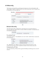
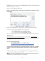
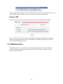
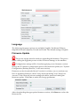
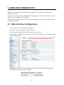
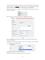
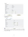
1
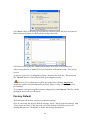
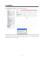
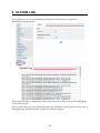
IP Video Server CC-8010, CC-8011, CC-8012 User`s Manual Firmwareversion 1.9.5 Document Version 1.4 Stand: October 2011 Convision Systems GmbH About This Guide The User’s Manual provides functionality and instructions for Convision IP video servers CC-8010, CC-8011 and CC-8012 employing firmware version 1.9.5. Before Using the IP Video Server Check the PC requirements Review the OS platform requirements Read an special and import precautionary information Having basic knowledge of network setup and configuration will be helpful Important Announcements NOTE: This icon represents a tip for operation. CAUTION: This icon stands for an action that could affect an operation or mildly impair the system. WARNING: This icon indicates an action that will likely impair the system. 1 INTRODUCTION 1.1 2 3 Model Differences THE LIVE VIEW 1 1 2 2.1 OSD (On-Screen Display) 2 2.2 Setup, Snapshot and Record Video 3 2.3 Video 3 2.4 Audio 3 2.5 SD Status 4 2.6 Control (PTZ Controls) 4 2.7 Camera Info and Digital Output 5 Camera Info Digital Output 5 5 THE SETTINGS PAGE – BASIC 6 3.1 Status 8 3.2 Network 8 Static IP Dynamic IP Address PPPoE Settings UPnP 8 9 10 10 Video 11 Stream 1 Video Setting Max Client Stream 2 Color Setting 11 11 12 13 13 3.4 Audio 15 3.5 Event Rule 15 Events Handled Actions Triggered Events and Actions Activating Events Modifying Activated Event Rules Deleting Events 16 16 16 18 18 19 Date & Time 19 Client PC Time Time Server 20 20 OSD (On-Screen Display) 20 3.3 3.6 3.7 4 THE SETTINGS PAGE – EXPERT 22 4.1 PTZ Control (Pan, Tilt, Zoom) 22 4.2 Port 23 4.3 DDNS (Dynamic DNS) 23 4.4 SMTP/FTP 24 Remote SMTP Setup Remote FTP Setup 25 26 Trigger Setup 26 Digital Input Periodic Timer Motion Detection Video Loss 27 27 27 29 4.6 Pre/Post Setting 30 4.7 SD Card 30 4.8 NAS Setting (Network Attached Storage) 31 4.9 Account 32 The Administrator Account User Accounts Guest Permission 33 34 34 Security 36 Network Security Power LED 36 39 Maintenance 39 Language Firmware Update System Configuration (Backup / Restore) Factory Default 40 40 41 42 4.5 4.10 4.11 5 REBOOT 44 6 SYSTEM LOG 45 7 LOGOUT 46 8 WIRELESS CONNECTIVITY 47 9 8.1 Web Interface Configuration 47 8.2 USB Configuration Port 51 ADDITIONAL INFORMATION 55 1 INTRODUCTION This document covers functionality and usage of the web interface for IP video servers with firmware version 1.9.5. Specific model information can be found in the model specification which can be found in the Installation Guide for the corresponding model. 1.1 Model Differences Although most of the operations and functions being the same amongst models, there are some differences. Differences are highlighted where applicable. The following table highlights primary functionality that differs between models. These differences will determine if certain items and settings will exist in the Live View and/or Settings page. Video Server CC-8010 CC-8011 CC-8012 SD Card PTZ Capable x x x x WiFi x Color OSD EtroLink x x For example, if a server do not support WiFi (e.g. CC-8010), then the WiFi settings option will not be present in the Settings page. 1 2 THE LIVE VIEW The IP server web interface is made up of two main pages: the Live View page and the Settings page. The Live View provides the current display from the IP server along with selected settings, configuration and functionality. After logging into the IP server via the browser, the user is first presented with the Live View page. Below is an example of the Live View page. Following the screenshot is a discussion of the different areas within the Live View page. 2.1 OSD (On-Screen Display) In the top left corner is the OSD (On-Screen Display). By default, the date and time are displayed in the format MM-DD-YYYY HH24:MI:SS; the server name can also be displayed (see “OSD” section for information on altering the OSD settings). 2 2.2 Setup, Snapshot and Record Video In the top right corner of the screen are three controls. “Setup” switches from the Live View page to the administration configuration page where most of the IP server configuration is performed. “Snapshot” can be used to take snapshot pictures. The files are stored locally on the PC. “Record Video” starts and stops recording of video. The files are stored locally on the PC. 2.3 Video Below the Setup/Snapshot/Record controls are the video and resolution controls. “Stream2” will also be displayed if it has been enabled (see the Settings Page “Video” section for more information). The resolution and bit rate can be modified here. In the drop down box, choose one of the options. Changes take place a few seconds after modification; the image on the screen might briefly pause while changes are implemented. 2.4 Audio The “Audio” check boxes enable/disable speaker and microphone (Mic) capabilities. The appropriate cables need to be connected into the back of the server. (See the “Audio” section for more information). 3 2.5 SD Status The “SD Status” is the secure digital (SD) card status. If no card is present then the status will be “Invalid”. See the “SD Card” section for more information. 2.6 Control (PTZ Controls) The Control section allows operating the PTZ controls from the Live View. The round dial with directional arrows controls the directional movement of the camera. “Preset” is used for configuring and using camera directional presets. There are two buttons: S and G. Focus, zoom and iris controls are modified using the + and – buttons. S is used to set a specific location view. First position the camera to view a specific area. Next click S which displays a window prompting the ID to assign the specific preset. Enter an alphanumeric ID for a specific preset and click OK. G is used to move the camera to a specific preset. Click G, enter the desired preset ID and click OK. 4 2.7 Camera Info and Digital Output Camera Info The 2 buttons on the bottom right are “Camera/Server Info” and “Digital Output”. The “Camera Info” button displays video information such as frame rate (fps), model name, and resolution. This information is displayed where the OSD information is normally displayed, the top left corner. Below are two screenshots displaying when the “Camera Info” button is enabled. Note that the OSD information is no longer viewable when the button is enabled. Digital Output The “Digital Output” control is a toggle button that sends a Digital Out signal. This functionality is available if a corresponding device is connected to the IP camera using the digital I/O terminal. 5 3 THE SETTINGS PAGE – BASIC The web interface is made up of two main pages: the Live View page and the Settings page. The Live View page interface was introduced in the previous section. The Settings page is primarily used for viewing and configuring the IP camera’s settings. From the Live View page, click the Settings page icon at the top right side: Below is a screenshot of the Settings page interface. The initial page displayed is the “Status” page. The left side of the page lists the different setting sections which can be viewed and modified. For example, clicking “Audio” will display the “Audio” configuration settings in the right pane. 6 From the Settings page, click the Live View page icon (highlighted in red in the upper right corner) to return to the Live View page. Configuration changes in the Settings page require clicking the OK button. Otherwise, changes will not be applied. The following discusses the different basic configuration options within the Settings page. 7 3.1 Status The Status page is always the initial page displayed when switching to the configuration view. Various basic information related to the IP server is displayed here. The page only displays information; no changes can be made here. 3.2 Network There are three available types of wired network connections available: STATIC, DYNAMIC and, PPPoE. Please confirm all network related settings with the network administrator prior to making any changes. Static IP 8 1. 2. 3. 4. Enter the IP Address. Enter the Subnet Mask/Gateway/Default DNS Be sure to press OK to save the new setting. A window prompting a reboot will be displayed. Click OK to proceed with the reboot (or Cancel if you wish to return to the Network settings). 5. A timer will countdown the approximate time for reboot to complete. The page will be redirected to the live view page using the new IP address. Use IP-Setup to find the MAC addresses after reboot and ensure the IP address is correct. If the IP was changed in web configuration, you must access the initial login page using the new IP after the reboot. Dynamic IP Address 1. 2. 3. 4. Select DHCP Press OK button Reboot will be required and automatically triggered after pressing OK. A window prompting a reboot will be displayed. Click OK to proceed with reboot (or Cancel if you wish to return to the Network settings). A timer will countdown the approximate time for reboot to complete. The browser will likely not reload since the IP is uncertain. The new IP address will likely need to be determined using IP-Setup and the IP server’s MAC address. After determining the new IP address, use this IP address to access the web interface. Always use IP-Setup to find the MAC addresses after reboot and double check the IP address. Make sure the IP address is correct. If IP was changed in web configuration, you cannot return to initial login page after reboot. 9 PPPoE Settings If the network supports PPPoE like xDSL, then PPPoE can also be used for connectivity. 1. 2. 3. 4. Select PPPoE Enter the PPPoE ID and password. Enter the MTU (Maximum transmission unit) The DNS server can be manually set or “Auto” can be used to automatically detect the DNS IP address. If xDSL does not use static IP addresses, then DHCP should be used. UPnP To enable UPnP (Universal Plug and Play) connectivity, check the “Enable UPnP” box. This will allow accessing the camera via UPnP connectivity from a computer. 10 3.3 Video Stream 1 Video Setting Stream Port: Stream 1 port value setting; 1852 is the default. Stream Protocol: TCP and UDP(RTP) Enable RTSP Authentication: option available if UDP(RTP) protocol selected Enable Multicast: option available if UDP(RTP) protocol selected Multicast Address: option available if multicasting enabled; the default value is 228.0.0.1. Verify address with the network administrator before applying Multicast Port: option available if multicasting enabled; the default value is 10000. Verify address with the network administrator before applying Multicast TTL: TTL (Time To Live); option available if multicasting enabled; the default value is 15 Video Compression Type: H264, MJEPG, MPEG-4 Resolution: this setting can also be set from the live view page Bitrate Type: constant bit rates and variable bit rates. The Bitrate option is not present when using MJPEG video compression Constant values range 64Kbps to 4Mbps; 2Mbps is the default. 11 Variable values range from 15 to 51; this value is relative quality of video. 15 represents highest quality video, and 51 the lowest quality video. Image Quality: not displayed in above screenshot; only available when using MJPEG video compression Frame Rate: (Frames per Second) values range from 1 to 30 GOP Size: GOP (Group Of Pictures); this function is designed for adjusting the ratio between “I” frames and “P” frames. This option is not available when using MJPEG video compression. A higher GOP size (i.e. 4 * FPS) results in lower bandwidth consumption, while a lower GOP size provides better picture quality. Video Servers also have an additional setting for NTSC and PAL. Click Detect, and the video server will probe the camera and set the appropriate value. 1M is recommended when using H.264; 1.5M is recommended when using MPEG-4. When mosaic or fragmentation occurs in the image, lower the frame rate or assign another level of image quality. Max Client This function allows more than one user to have the access to the video stream. The relationship between bit rates, resolution, and the client amount is inversely related. The maximum number of clients depends on the network bandwidth and the required video quality. Values can range from 0 to 10. 12 Stream 2 With the exception of the “Stream Enable” checkbox and the “Stream Port”, the settings in stream 1 and 2 are the same (the above example do not reflect the default values). If stream 2 is enabled, then this stream can also be viewed in the Live View page. Color Setting Note: Color Settings vary between camera models. The following screen shot is from an IP camera with many of the video adjustment options for this firmware version. Some models may have more or only have a subset of these settings. The color settings allow making adjustments to video quality. Any adjustments to a setting will automatically be displayed in the Color Setting preview window after a few seconds. Click OK to apply any changes or Reset to rollback any unsaved changes. 13 Brightness: Adjusts the brightness of the image. Contrast: Adjusts the variation in the intensity of an image. Saturation: Adjusts the intensity of color in the image. AGC: Auto Gain Control; gain helps brighten dark images. AEC: Enables auto exposure control. AWB: Enables the automatic white balance control. Mirror: Flip the image horizontally. Flip: Flip the image vertically. Lighting Frequency: Adjusts for flickering effect caused by artificial lighting. Options include 50Hz and 60Hz. DC Iris If the IP camera is using a lens with a DC iris (auto iris) then the auto iris functionality will be displayed in the video settings. IRIS: check to enable auto iris 14 3.4 Audio The audio settings control the level of audio in and out. The values range from 0-10 (0 the minimum; 10 the maximum). After changing the volume setting, click OK to apply the changes. 3.5 Event Rule The IP servers CC-8010, CC-8011 and CC-8012 are capable of handling all standard events. 15 Events Handled Digital Input: is a circuit which is defined as on (Normal Open (N.O.)) or closed (Normal Close (N.C.)) Motion Detection: If a motion is detected in the defined areas, an event will be triggered. Periodic Timer: An event will be triggered following the schedule of the predefined time interval. For example, if the time interval is set to 30 seconds, the event will be triggered once every 30 seconds. Network Loss: When network loss is detected, an event will be triggered. Video Loss: When a video server detects a loss of video input from camera. Power Loss: When system power loss is detected, and event will be triggered. The e-mail notification includes the duration of the power loss. Actions Triggered Digital Output: Activate digital output. E-mail Notification: E-mail can be sent based on occurrence of an event listed out in “Rule Lists”. Record: When an event is triggered, the system will record streaming video to an FTP Server or NAS storage server. Certain triggers (Digital Input, Motion Detection and Periodic Timer) also have settings related to that specific event. Below highlights event settings related to the Motion Detection trigger. Events and Actions The following table lists the various events, or triggers, and the available methods of handling each trigger Trigger/Event Handler/Action Digital Input Digital Output PTZ Preset* Email Notification Record Motion Detection Digital Output PTZ Preset1 Email Notification Record 1 PTZ Preset is only available for those models that support PTZ functionality. 16 Periodic Timer Digital Output PTZ Preset* Email Notification Network Loss Digital Output Video Loss2 Digital Output Email Notification Power Loss Email Notification These additional trigger settings also correspond to the settings in the “Trigger Setup” configuration view (See “Trigger Setup” for more information). By clicking “Change Settings”, the browser window will be redirected to the corresponding section in the configuration view (i.e. SMTP/FTP). The user will first be asked about saving, or activating, the rule. OK saves the rule; Cancel doesn’t save the rule. In either instance, the browser will then be redirected to the corresponding configuration page. In addition, the Handler actions also have additional settings displayed. Below is the Email Notification handling action for the Motion Detection trigger. 2 Video Loss is a video server event; IP cameras will not list this event. 17 The area highlighted in red is settings which can also be set via the “SMTP/FTP” configuration view. However, the area highlighted in blue, “Trigger Interval”, is a setting specific to the Motion Detection/Record handler; other Email Notification handler actions may or may not have the “Trigger Interval” setting. Below is an example of an Email Notification handler not using this setting. Activating Events To activate an event, first select the event and corresponding actions. Next press ADD button to activate the event; the event will be added to the “Activated Event Rule” pane. Lastly, click the OK button located at the bottom of the page to save the changes. The activated event handler will be disabled in the “Trigger and Handler” pane. The following shows the Power Loss/Email Notification has been disabled after activating this event. Modifying Activated Event Rules To modify an event that has already been activated, first highlight the event in the “Activated Event Rule” pane. Below the Network Loss event has been highlighted for modification. 18 In the “Trigger and Handler” pane, the current settings for the activated event are displayed. These can be changed as has been done below in the red highlighted areas. After making any desired changes, click Modify to see the changes in the “Activated Event Rule” pane. Lastly, click OK at the bottom of the page to apply the changes. Deleting Events To remove an event, select the event in the “Activated Event Rule” list, then click the Delete. Next click OK at the bottom of the page to save the changes. Clicking Delete All removes all the events in the “Activated Event Rule” list. 3.6 Date & Time The “Server Time” displays a snapshot of the time as it was when the page was accessed. The time displayed here will not increment. The “Time Zone” drop down box offers a selection of time zones to apply to the IP camera. 19 Client PC Time The “Client PC Time” is used to synchronize the IP camera with the time of the PC accessing the Settings page. “Client PC Time” will display the current time of the PC. To synchronize the camera with the PC time, choose the “Client PC Time” option if not already selected and click OK at the bottom of the page. Time Server A Time Server can be also be used to maintain time accuracy. It synchronizes every hour. To use a time servers, choose the “Time Server” option. Next select one of the two time server options (pool.ntp.org, time.windows.com) or define one by selecting “Other”. “Other” will present another field, “User Assign”, where the desired time server can be defined. After choosing a time server, click OK to apply the changes and update the time. 3.7 OSD (On-Screen Display) The OSD and Camera Info displays are independent. The OSD settings relate to information (i.e. time) displayed along with the video from the camera. In addition, the OSD section also controls the name associated with the IP camera. The OSD details are presented in the top left corner of the Live View. By default the date and time are displayed. The “Camera Name” is a user-defined name given to the camera. The camera name must be a-z, A-Z, 0-9, and “-”; character spaces aren’t permitted. 20 The timestamp overlay of the video can be enabled/disabled via the “Enable Timestamp Overlay” checkbox. The camera name can also be enabled/disabled via the “Show camera name” check box. The camera name will appear below the time & date. 21 4 THE SETTINGS PAGE – EXPERT The following continues the description of the different configuration options within the Settings page 4.1 PTZ Control (Pan, Tilt, Zoom) Note: Only Video Servers, Box and Megapixel Cameras will have this configuration option as of this firmware version. To configure the PTZ Control configuration, please refer to the manufacturer’s PTZ specifications. The PTZ Control settings will depend on these specifications. The following is a listing of the available PTZ Protocol settings. Based on the manufacturer’s specifications, select the appropriate value for PTZ Protocol, Device ID, Baud Rate, Data Bits, Parity and Stop Bits Device ID. 22 4.2 Port The “Web Port” is used to access the IP camera’s web interface. The default value of Web Port is 80. The “Configuration Port” is used for integrating applications with the IP camera. The default port is 1150. If the default port is changed (e.g. 8080) users must add the port number to the IP address (10.1.21.5:8080). 4.3 DDNS (Dynamic DNS) DDNS is used to map a dynamically assigned IP address (a device using DHCP) with a hostname. Certain network configuration will likely be required (i.e. mapping the IP address recognized by the DDNS service to the IP camera) to implement DDNS. Therefore, the network administrator will likely need to be consulted. If the IP camera uses DHCP, a DDNS service can provide a hostname for use with the IP camera. Registration with one of the DDNS service providers (ddns.nu, dyndns.org) is required for use of this feature. 23 To enable DDNS, check the “Enable” box. After registering with one of the DDNS services, enter the hostname, DDNS ID and DDNS Password. After configuring the DDNS and any networking modifications, the web interface can be accessed via the hostname (i.e. http://[email protected]). 4.4 SMTP/FTP The IP camera can be configured to send notifications via email. In addition, the IP camera can also upload video and images using ftp. 24 Remote SMTP Setup The SMTP settings allow the IP camera to send email notifications to a recipient’s email account. These settings are used by various event triggers (i.e. Motion Detection) defined in the in the “Event Rule” settings page. The following parameters should be modified with the appropriate email settings. Please verify this information with the email account administrator. 25 After entering the appropriate email account settings, click OK at the bottom of the screen to apply the changes. Next the email configuration needs to be tested. The “Connection Test” requires two steps. 1. In the “Connection Test” field, click Test SMTP. If an error is encountered, then review the email settings, make the necessary changes, and try the Test SMTP again until the “Ready to verify SMTP setting” is displayed. 2. After receiving the status “Ready to verify SMTP setting”, verify the email settings work with the SMTP server by clicking “Test SMTP” again. If an error is encountered, then review the email settings, make the necessary changes, and try the Test SMTP again until the “Verify SMTP success” message is displayed. No test email will be sent during the above configuration. Upon receiving “Verify SMTP success”, email notification should be properly configured and ready for use. Click OK to apply changes. Remote FTP Setup Enter the address of the FTP server, port number, user name, and password. Passive Mode may be required if the IP camera is accessing an FTP server outside of a firewall. Click OK to apply changes. 4.5 Trigger Setup For proper operation, ensure the mini DIN cable has been properly connected to digital I/O and RS-485 devices. 26 Three different events can be triggered. Digital Input There are two selectable options: Normal Open (N.O.) and Normal Close (N.C.) N.O. represents the circuit should remain open; consequently, closing the circuit represents the trigger. N.C. represents the circuit should remain closed; consequently, opening the circuit represents the trigger. Choose the proper option depending on the input type; press OK to save the setting. Periodic Timer The Periodic Timer will automatically trigger an event based on the time interval. Set the appropriate value in seconds, and click OK to apply the changes. Motion Detection The “Motion Detection” trigger will trigger an event upon detecting motion in a specified area of viewing. Detection Setting Below is the “Detection Setting” section of the “Motion Detection” settings page. 27 The first step to enable motion detection is to check the “Enable Motion Detection” option. Below the “Enable Motion Detection” check box are detection area settings. While “Enable Motion Detection” may be enabled, no events will be triggered if no detection areas are defined and enabled. The example above has two areas enabled (area 1 and 2). In the area displaying the camera view, motion detection areas 1 and 2 are defined by shaded areas. If an area is disabled, the defined area will remain, but will be grayed out. The “Draw” and “Clean” functions are also available in the Detect Area settings. 28 The “Draw” option defines which area (1, 2 or 3) can be defined in the viewing portion at the top of the page. Using the mouse, the user clicks the left mouse button, holds and drags to define an area. The Clean button removes the corresponding detection area. “Sensitivity” defines the sensitivity of the motion detection sensor for triggering an event. Sensitivity values range from -10 (the least) to +10 (the most). Schedule Setting Along with the area detection settings, the “Schedule Setting” portion of the settings page allows scheduling when the IP camera monitors for motion detection. “Enable Type” provides two options: “Always” and “Schedule”. Choose “Always” if the IP camera should continuously perform motion detection. “Schedule” allows configuring the IP camera to selectively determine when motion detection should occur. Selecting “Schedule” will allow choosing a start/stop time along with specific days to perform motion detection monitoring. Click OK at the bottom of the page to apply any changes. Video Loss Note: Video Loss will only be found in video servers. 29 The Video Loss trigger will generate an event if video from the analog camera is lost for a certain period of time. The default value is 10 seconds. After setting a value, click OK to apply the setting. 4.6 Pre/Post Setting These settings configure the stream format type, duration of pre/post buffer video, and storage method when a trigger handler is set to “Record”. Format: options include “AVI” (for video file) and “JPEG” (for picture file). Pre-record Time: duration of video prior to the event trigger to be recorded Post-record Time: duration of video after the event trigger to be recorded Record To: options include “FTP Upload” and “NAS Storage”. Clicking Change Settings will redirect the browser to the corresponding settings page (i.e. “NAS Setting” settings page). 4.7 SD Card Note: Dome, Outdoor and Speed Dome models do not have SD Card functionality as of this firmware version. A high capacity SD memory card can be used for storing video and images. After inserting the SD card, the camera will automatically detect the card. If the card has never been used, then the card may be listed as unavailable or unformatted. If the camera has been previously used for other applications, then the SD card information may resemble the following. 30 Next format the SD card. This step is required to insure proper formatting and creating the necessary directory structure. Click Format SD Card. A confirmation dialogue will be displayed. Click OK to format the SD card. After the card has been formatted, a notification will be displayed. The SD card is now ready for use. 4.8 NAS Setting (Network Attached Storage) The NAS settings define the network storage parameters. To implement NAS, check “Enable”. 31 Protocol: defining the protocol for file sharing; the two options are SMB (Server Message Block) and NFS (Network File System) IP Address: the IP address of the where the network storage resides Folder: the directory which the IP camera will access for file storage Username: username for establishing NAS connectivity Password: corresponding password Connection Status: displays the status of the NAS connection; “NAS is not connecting” or “NAS is connecting” After configuring and clicking OK, check the “Connection Status”. The following illustrates a successful NAS connection. 4.9 Account The Account settings page allows the administrator to manage user and guest accounts. 32 The Administrator Account It is recommended changing the administrator (root) password after the initial network configuration. The ID of administrator can not be changed or deleted; only the password is changeable. Forgetting the root password will require resetting the IP camera’s default factory settings to regain root access. See “Reset Default Factory Settings” for more information. Administrator has the authority to view and control system settings. To change the administrator (root) password, click Password for the root User ID. The administrator account, root, cannot be changed or deleted. Only the password is changeable. A new page will be displayed for changing the root password. Enter the appropriate information and click Modify. 33 The administrator account, root, cannot be changed or deleted. Only the password is changeable. User Accounts The administrator can also create new user accounts (up to five additional users). User accounts can be created by entering the “User ID” and password, then clicking Add. Users can be assigned different combinations of authorities including video settings (V/S) and digital out (D/O). There are limits to the length of user’s name and password. If the length exceeds the limit, a dialog box will appear for notification. Guest Permission “Guest Permission” corresponds to a special account, guest. Enabling this account allows browser access via the guest account. This account doesn’t require a password. 34 The “guest” account is limited to viewing Stream1, Stream2 (if enabled) and “Camera Info”. 35 4.10 Security The Security settings allow restricting network access to the web interface and video/audio output. In addition, the Power LED on the back of the IP camera can be disabled for security purposes. Network Security The Network Security settings allow restricting access to the IP camera by network addresses. There are two modes which are available: Pre-defined Level, Customized by IP Filter. Pre-defined Level The default setting is “Pre-defined Level” and “LOW” which allows connections from anywhere. The “MEDIUM” and “HIGH” settings present restrictions based on if the connections are local to the IP camera or outside of the local area network. Customized by IP Filter The Customized by IP Filter allows greater flexibility in defining access to the IP camera. 36 The “Default Rule” defines if the emphasis is on exclusion or inclusion. “Deny All” will deny access to all except for those who are granted access. Conversely, “Allow All” will allow access to all except for those who are excluded. In the pane below “Default Rule”, rules will be defined which allow/exclude access to subnets and/or specific IP addresses. The rules are evaluated in order starting from the top and moving down. The Up and Down buttons can move rules up and down. The order of the rules is important, and will be illustrated in an example in the next section. Near the bottom are the settings for defining rules. IP: an IP address; this can represent a subnet Netmask: the netmask of the IP address Service: Stream 1, Stream 2, Web (port), Configuration (port) Policy: Allow or Deny Add adds the rule to the rule pane above. Edit will allow edits to an existing rule. First highlight the rule in the rule pane, edit the information in the rule settings, and click Edit to apply the changes. 37 Delete will delete a specific rule, while Delete All will delete all the existing rules. Click OK to apply any changes. Customized by IP Filter Example Below is a screenshot which will be used for explaining the Customized IP Filter functionality. Firstly, the “Default Rule” is “Deny All”. So, all access by default is denied. However, two rules have been defined in the rule pane. Here we are allowing access to the IP 10.1.20.138/255.255.240.0 for the Web and Stream1 service. While it appears we are only allowing access to 10.1.20.138, we are actually allowing access for those on the same subnet. Despite access to Web and Stream1, 10.1.20.138 cannot access Stream2. The “Deny All” requires that this be granted for access. Next we add the following rule. This rule is denying Web access to 10.1.20.140. Although, “Deny All” is currently in effect, 10.1.20.140 is on the same subnet. It has access via 10.1.20.138 having access. Despite adding the rule to deny 10.1.20.140, 10.1.20.140 still can access the web interface because of the order of evaluation. The rule denying 10.1.20.140 comes after the rule allowing access to 10.1.20.138. Therefore, the 10.1.20.140 must be moved to precede the rule allowing access to 10.1.20.138. We use the Up button to move the rule. 38 After applying the changes, 10.1.20.140 cannot access the web interface. However, others on the same subnet as 10.1.20.138 can access the web interface. Power LED The Power LED on the back of the IP camera can be enabled and disabled. If the “Turn Off” option is chosen, the light will remain off unless the camera is rebooting. During the reboot the camera light will blink; the light will remain unlit after finishing the reboot. 4.11 Maintenance The Maintenance section allows for configuring language settings, firmware updates, IP camera configuration backup/restore operations, and restoring factory default settings. 39 Language The following language options are available: English, Traditional Chinese, Simplified Chinese, Japanese, French and Polish. The default setting is English. Firmware Update The power supply must be steady as upgrading the firmware. The power failure during the upgrade process results in serious damage to the machine. Configuration settings will be lost after applying a new firmware version. Backup the IP camera’s configuration prior to the firmware update (see “System Configuration (Backup/Restore)” in the next section). Firmware can be downloaded from Convision’s website, www.convision.com. Prior to updating firmware, check “Keep Network Setting” and “Keep User Account” if the network/account settings should be preserved during the firmware update. Click Save to make the change permanent. After downloading the appropriate firmware version, click Browse to select the firmware file. 40 Caution: No confirmation will be provided after clicking Upload; the firmware update will automatically proceed. Please verify everything before proceeding. After selecting the firmware file, click Upload. A sequence of messages will follow. No IP camera operations should be performed during this time. Next… Lastly… After the reboot is complete, the camera will have the factory default network settings. These will need to be modified. After logging into the web interface, check the “Firmware Version” field in the “Status” Settings page to confirm the firmware has been successfully updated. System Configuration (Backup / Restore) The current configuration settings can be backed up to a file on the PC which can be restored if necessary. Clicking Export will open an additional IE window and the following prompt. 41 Click Save which will bring up an explorer window where the user can choose the location and name for the backup configuration file. Click Save to save the file, additional prompts should be self-explanatory. After saving the file, a blank IE browser window will remain open. This can be closed. To restore a previous configuration from a backup file, click the “Restore from file” Browse button. Select the backed up configuration file. Caution: No confirmation will be provided after clicking Import; the firmware update will automatically proceed. Please verify everything before proceeding. To continue with restoring the system configuration, click Import. The file will be uploaded and a reboot will ensue. Factory Default This function will restore the factory default settings. Prior to restoring the factory default settings, check “Keep Network Setting” and “Keep User Account” if the network/account settings should be preserved during this process. Click Save to make the change permanent. 42 Click Factory Default to restore the factory default settings. A confirmation dialogue window will be displayed. Click OK to proceed or Cancel to abort. The system will reboot following confirmation; wait for the countdown timer. After rebooting the system will refresh the screen. 43 5 REBOOT Pressing Reboot will display a confirmation dialog box. Press OK to continue with the reboot; the reboot countdown timer will start running. After finishing, a prompt for refreshing the page will appear. Confirming will log the user back into the Live View page. 44 6 SYSTEM LOG The System Log is a log containing information which may be needed for troubleshooting purposes. The log entries have a timestamp which start from the oldest and go down the page to the most recent. Most of the entries are only informational and will likely only be used in the event of investigating a problem with Convision Technical Support. 45 7 LOGOUT Logout will log the user out of the IP camera web interface. This will require the user to input user/password credentials when logging back into the web interface. Pressing Logout will exit the Settings page. Clicking Logout will display a confirmation dialog box. Select Yes to close the IE browser window. 46 8 WIRELESS CONNECTIVITY With an Convision supported wireless dongle, the IP camera can be used on a wireless network. There are two methods for enabling and configuring wireless connectivity: the web interface, the Configuration USB port. The methods described below will assume configuration of a new IP camera using the factory settings. 8.1 Web Interface Configuration First connect the LAN cable to the camera. Insert the wireless dongle into the WiFi port. Plug the power adapter and wait for the camera to boot. Log into the web interface (i.e. http://192.168.1.2). Navigate to the “Status” page in the Settings page. In addition to the LAN network settings, the “Status” page will also display details related to the wireless dongle. 47 One important consideration is that the LAN network interface and the wireless network interface use different MAC addresses. This is an important distinction when searching for the IP address of the camera when using DHCP. There is also a new entry, “Wireless”, on the Settings menu items located on the left side of the page. Select “Wireless” to display the wireless configuration settings. Before enabling the wireless network interface, check if the desired wireless network is available. Click Search in the “Station Setting” section. After a moment, a list of available wireless networks should be listed. Highlight the wireless network to connect to. Check the “Enable” box to implement wireless connectivity. 48 Enter all the relevant information for the specified SSID. Click OK to apply the settings. A confirmation will follow; click OK. Another confirmation will follow which is noting that the network configuration needs to be updated. Following this dialogue, the network settings screen will be displayed. Click OK. Now the Network configuration settings will be presented. 49 Change the configuration settings to apply to the wireless network. For this example, DHCP will be used. Click OK to apply the changes. Two confirmations will follow; click OK for both. Next the reboot timer screen will be displayed. Now the LAN cable can be unplugged. 50 Since this example assumes DHCP is being used, use IP-Setup to find the IP address after the reboot. Use the wireless dongle’s MAC address, not the MAC address for the LAN interface. Using the MAC address of the wireless dongle, the camera’s IP address is identified. This IP address can be used to access the IP camera’s web interface. 8.2 USB Configuration Port Unlike the web interface method of wireless configuration, the Quick Config utility doesn’t display the wireless network interface’s MAC address. Refer to the label on the dongle or the packaging for the MAC address. Use The MAC address can be obtained from the label on the dongle or the packaging. Unplug the power adapter and the LAN cable. Insert the wireless dongle into the WiFi port located in the read of the camera Connect the IP camera and the PC using the mini USB cable. Once the PC has recognized the IP camera, select “Config Wizard” in the program option list (or start it manually per instructions in the “Configuration Port” section). Assuming no changes have been made to the administrator account, enter “pass” for the root password. The “Status” screen will now have a “Wireless Information” section. 51 Click Quick Wizard to continue. Check the “Enable” box, enter the information for a specific SSID, and click Next. Choose the appropriate network connection type for the wireless network. DHCP is used for this example. 52 Click Next to continue. Click Next to continue. Change the ports if different from the default values. Click Next to continue which will display a confirmation dialogue; click OK. Click Finish to exit the Quick Config utility. 53 Unplug the IP camera from the PC, and connect the power adapter to the IP camera. After the camera starts, IP-Setup can be used to identify the IP address. However, the Quick Config doesn’t display the MAC address, so this will need to be obtained from the wireless dongle or the packaging. Using IP-Setup, the IP address can be found. This IP address can be used to access the IP camera’s web interface. 54 9 ADDITIONAL INFORMATION For more information please reference the IP camera/video server Installation Guide. This manual is available on the product CD, or it can be downloaded from the Convision website, www.convision.com. In addition, the latest firmware releases and other product documentation are available in the Download area. 55