1
5
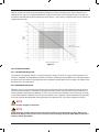
With this analyzer, the sensor (Zirconia element) is heated up to 750˚C, so Equation (2) is valid. At that point, the
relationship as in Figure 2.1 is effected between the oxygen concentration of the measurement gas in contact with
the positive electrode and the electromotive force of the sensor (= cell), where a comparison gas of air is used on the
negative electrode side.
Figure 2.1
2.2 CALIBRATION GASES
2.2.1 CALIBRATION (ZERO) GAS
The calibration gas typically used is 1% oxygen balanced in nitrogen; however, an oxygen mixture between 0.4%
and 8% is acceptable. A compressed gas cylinder is containing certified gas mixtures fitted with a dual stage regulator
should be used. The maximum working pressure of the calibration systems (MC1 & AC1) is 35 psig. The reference gas
should be clean, dry instrument air.
2.2.2 REFERENCE (SPAN) GAS
Reference air is from the same source as the span gas. The reference air flows to the backside of the of the Zirconia
cell, and is used at all times. The calibration units are plumbed to provide a continuous flow rate of the reference, as
well as, calibration gas flow during calibration. A clean, dry air source is recommended, such as instrument air. Install
an inline filter before the calibration unit to remove any moisture or dirt. A regulator must be attached to the instrument
air source to provide the appropriate working pressure for the calibration unit. The maximum pressure is 35 psig.
NOTE
Never use pure nitrogen for calibration.
NOTE
Compressed gas cylinders must have the same CGA connection as the dual stage regulator. Refer to the
Appendix A (Spare Parts section) of this manual for the Dual Stage Regulator (M1132ZX) and the Zero
Pressure Switch (M1133AR).
IM 11M06D03-01E-A