1
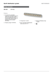
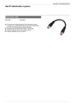
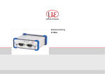
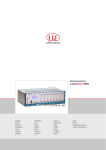
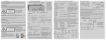
5. 6. Laser Safety The scanCONTROL 26xx/29xx sensors operate with a semiconductor laser having a wavelength of 658 nm (visible/red). The laser operation is indicated visually by the LED on the sensor. Connections, LED Displays 2 1 scanCONTROL 26xx/29xx sensors with a maximum laser power up to 8 mW are classified in Laser Class 2M (IIM). The following information labels are fitted to the sensor housing (front and rear side). If both information labels are hidden in the installed state, the user must ensure that additional labels are fitted at the point of installation. Assembly Instructions scanCONTROL 2600/2650/2900/2950 1 Ethernet port 2 Multifunction port (Power supply, IO) Laser radiation Do not stare into the beam or view directly with optical instruments Class 2M LaserProduct 1. Ethernet Connection, Standard Connection to PC IEC 60825-1: 2008-05 P0 ≤ 8mW, PP ≤ 8mW; H ≤ 52W/m2; = 658nm; F = 0...4kHz, t = 1s...∞ Hazard to the eye via laser radiation! Consciously close your eyes or turn away if the laser radiation impinges on the eye. Lasers of Class 2M are not subject to notification and a laser protection officer is not required. Mark the laser area recognizable and everlasting. Warnings Connect the power supply and the display-/output device in accordance with the safety regulations for electrical equipment. The power supply must not exceed the specified limits. RJ45 connector 8-pin screw connector (sensor side) >> Danger of injury, damage or destruction of the sensor Pin no. Color stranded hook-up wire SC2600/2900-x Pin no. 10BaseT, 100BaseTX 1000BaseT 1 white (orange) 5 Tx+ D1+ Avoid shock and vibration to the sensor. Avoid continuous exposure to dust and spray on the sensor. Avoid exposure to aggressive materials (e. g. washing agent, penetrating liquids or similar) on the sensor. 2 orange 6 Tx- D1- 3 white (green) 8 Rx+ D2+ >> Damage to or destruction of the sensor Read the detailed instruction manual before operating the sensor. You will find this manual on the provided CD or online at www.micro-epsilon.com. Laser Class 3B 4 blue 1 D3+ scanCONTROL 26xx/29xx sensors with a maximum laser power up to 50 mW are classified in Laser Class 3B (IIIB). 5 white (blue) 2 D3- 2. 6 green 7 D2- 7 white (brown) 3 D4+ The following applies to the scanCONTROL 26xx/29xx: EMC Regulation 2004/108/EC The sensor fulfills the specifications according to the following standards 8 brown 4 D4- Injury to the eye or the skin via laser radiation! Consciously close your eyes or turn away if the laser radiation impinges on the eye or the skin. Class 3B (IIIB) laser sensors are notifiable and a laser protection officer is required either. During operation the laser area has to be restricted and marked. The following information label should be fitted to the sensor housing (front and rear side): 1 View on pin side male cable connector Rx- 2 1 8 4 7 6 Laser radiation Avoid exposure to beam Nicht dem Strahl aussetzen ClassLaser 3B Laser KlasseProduct 3B IEC 60825-1: 2008-05 nach PDIN EN 60825-1:2001-11 50 mW; P 50 mW; O P = 658 nm; F = 0...4 kHz, t = 1 µs...∞ Beam attenuator The beam attenuator prevents access to all laser and collateral radiation. The figures show the sensor with closed and open beam attenuator. The beam attenuator must be open during measurement. i Sensors of Laser Class 3B (IIIB) need an external key switch to switch off the laser, see Chap. “Laser switching”. -- DIN EN 55011/ 11.2007 (Group 1, Class B) / Industrial scientific and medical (ISM) equipment / Electromagnetic disturbance characteristics -- DIN EN 61 000-6-2/ 03.2006 / Electromagnetic Compatibility (EMC) / Immunity to interference / industrial area -- DIN EN 61326/ 10.2006 / Electrical equipment View on solder pin side screw connector 3 The sensor fulfills the specifications of the EMC requirements, if the instructions in the manual are followed. 5 -- The sensor supports an automatically, sensor-adapted IP address in the link-local-net (169.254.x.x). No collision detection is implemented. This is also the default setting. -- The sensor supports DHCP. This setting is activated by default and has priority over the retrieval in the link-local-net. -- The sensor scanCONTROL 26xx/29xx supports Power over Ethernet. If the sensor is connected to a network adapter/switch that is capable of POE and if you also use the power supply of the multifunction port, these two power supplies have to be galvanically isolated. >> Damage of the sensor and/or the Ethernet card! -- A fixed IP address can be assigned. Use the program “SensorFinder“ delivered on the CD, to make the above-described sensor settings. Notes on CE Identification 3. Proper Environment 4. Scope of Delivery of scanCONTROL 26xx/29xx ----- -- 1 Sensor scanCONTROL 26xx/29xx with integrated controller -- 1 Multifunction cable PC2600/2900-5, length 5 m; for power supply, trigger and RS422; Escha screw connector and free cable ends -- Sensor acceptance report / assembly instructions -- 2 protective caps -- scanCONTROL Demo-CD with drivers, programs and documentation www.micro-epsilon.com MICRO-EPSILON Messtechnik GmbH & Co. KG Königbacher Str. 15 94496 Ortenburg, Germany, Tel. +49 (0) 85 42/1 68-0 *X9771299-A02* Protection class: IP 65 Operating temperature:0 to +45 °C (+32 to +113 °F), by free circulation of air Storage temperature: -20 to +70 °C ( -4 to +158 °F) Humidity: 5 - 95 % (non condensing) X9771299-A031015HDR Multifunction Port Designation Sensor connector Cable color Pin PC2600/2900-x +Ub 9 red Notes + 11 V - 30 V DC (rated value 24 V); max. 500 mA GND 2 blue +Laser on/off 3 white -Laser on/off 1 brown RS422 12 red-blue /RS422 11 gray-pink In1 6 yellow GND-In1 4 green Ground In1 In2 5 pink Digital Input 2 0V The sensors of the scanCONTROL 26xx-x/SI and scanCONTROL 29xx-x/SI series offer this function. Digital Input I Ground In2 GND-In3 7 black Ground In3 LED “laser on“ Green: Laser on Housing black No galvanic connection to GND LED “state“: Two-color LED (red / green) Green: Measurement Green flashing: Data transmission Red flashing: Error code 12-pin screw connector, view on solder pin side 5 9 8 12 7 GND: galvanically isolated from 1, 2, 3, RS422, Laser on/off 6 If the software shows the error message “No scanCONTROL found” in the status line, please check the Ethernet connection between scanCONTROL and PC. RS422, input respectively output Digital Input 3 11 Now start the scanCONTROL Configuration Tools software. Click on “Display Profiles“ in the main window. C. Further informations in the online documentation gray 4 First Profile B. Installation of software purple 1 9. A. Reading of installation help optional 8 3 Please insert the scanCONTROL Demo CD in the CD-ROM device. Follow the dialog through the installation process. LED Displays 10 2 Install the software. You will find details for the wiring in the instruction manual, Chap. 5.2.6. GND-In2 10 Quick Start: Commissioning, Software Use a serial key switch inside the control circuit to switch off the laser. In3 Shield 8. External Laser Switching Laser on/off: Input galvanically isolated from GND, IN1…3, RS422 IN1, IN2, IN3, RS422: Inputs galvanically isolated from GND and Laser on/off RS422, Synchronization The RS422 connection (Pin 11 and 12 of the multifunction port) can be used with either of the following configurations: -- RS422 (half-duplex): Load user modes and sensor control. -- Synchronization/triggering: Synchronization respectively triggering using switching signals. Trigger, Encoder, Mode Switching The switching inputs of the multifunction port can either be used for encoder input, for trigger input or for loading previously stored user modes. The signal levels are switchable for all switching inputs between LLL (low-voltage-, TTL logic) and HLL (high-voltage-, HTL logic): -- LLL level: Low 0 V … 0.8 V, high 2.4 V … 5 V, internal pull-up 10 kΩ to 5 V -- HLL level: Low 0 V … 3 V, high 11 V … 24 V (permitted to 30 V), internal pull-up 10 kΩ to 24 V -- Pulse duration: ≥ 5 µs Mount the sensor according to the installation instructions. Connect the sensor to the PC via the Ethernet cable. Note: The “state“ LED flashes green, long during active data transmission and short for controller accesses. Connect the sensor to display or monitoring units. Connect the sensor to the power supply. The connectors for Ethernet and the multifunction port are fitted with an Escha screw connector. Die “state” LED indicates different error conditions by flashing. If no flashing occurs for several seconds, no error has occurred. For a detailed description of the error codes, please refer to the instruction manual, Chap. 11. 7. System Requirements scanCONTROL Software -- Windows XP SP2 (32 bit) / Windows Vista (32 bit) / Windows 7 (32 bit and 64 bit) -- Pentium III ≥ 800 MHz / 512 MB RAM -- Screen resolution: 1024 x 768 Loosen the screws before you remove the connector from the socket. i Connect the shield of the power supply cable to the PE protective earth conductor of the main power supply. Close unused connection plugs with the provided protective caps. Switch on the power supply (24 VDC). Only connect the sensor to the peripheral equipment, if it is disconnected from the power supply, i.e. only when the operating voltage is switched off. The sensor needs a warm-up time of typically 20 minutes for high precision measurements. Please wait until the scanCONTROL device is recognized by the PC. This may take a few seconds. Now you can operate the scanCONTROL measurement system with the scanCONTROL software packages. i Operating a scanCONTROL sensor via Ethernet may require a modification of the IP settings of the PC/sensor or a modification of the firewall settings, see Chap. 5.2.5 of instruction manual. On the left side you can adjust the settings for your measurement task, the right side shows the profile data and information about the measurement. 10. How to Access Profile Data Profile data of scanCONTROL can be accessed via: -- GigEVision and GenICam for digital cameras via Ethernet interface -- SDK for fast application integration (C, C++, C# and others) For details how to access profile data refer to the enclosed online manual. 11. Further Information Please refer to -- the enclosed online manual -- the section “Status and Error Messages“ and “Notes“ in the scanCONTROL Configuration Tools manual. You will find details to the separate programs in the respective instruction manuals or in the instruction manual of this sensor, Chap. 6.2. You will find the instruction manuals online or on the provided CD.