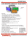
1
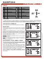
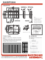
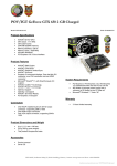
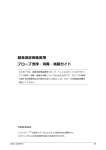
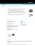
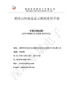
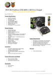
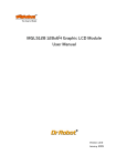
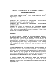
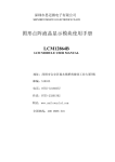
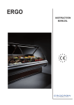
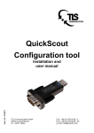
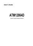
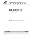
EA DIP128-6
8.2008
LCD-GRAPHIC MODULE 128x64 DOTS
EA DIP128J-6N5LW
EA DIP128J-6N5LE
pins
with
EA D
IP1
28-6
N5L
WT
P
FEATURES
*
*
*
*
*
*
*
*
*
*
*
*
EA DIP128J-6N5LA
75,0 x 45,8 x 10,8 mm
REAL BRIGHT AND CONTRASTY GRAPHIC DISPLAYS
EA DIP128-6N5LW: WHITE DOTS, BLUE BACKGROUND
EA DIP128J-6N5LW: BLACK DOTS, WHITE BACKGROUND
WITH AMBER BACKLIGHT (LONGLIFE)
GREEN VERSION FOR HIGHEST CONTRAST
LOW-POWER LED BACKLIGHT min. 15mA, max. 90mA@+25°C
INTEGRATED CONTROLLER KS0107/108 OR PT6607/08
TEMPERATURE COMPENSATION BUILT-IN
8-BIT BUS INTERFACE
NO MOUNTING REQUIRED: JUST SOLDER INTO PCB
POWER SUPPLY +5V
OPERATING TEMPERATURE RANGE -20°C..+70°C
ACCESSORIES
* MATRIX TOUCH PANEL 5x3, ANTIGLARE AND SCRATCH-PROOF
* HIGH-LEVEL-GRAPHICS-CONTROLLER FOR RS-232: EA IC202-PGH
ORDERING INFORMATION
LCD GRAPHIC MODULE 128x64 DOTS BLUE-WHITE
SAME BUT IN BLACK/WHITE OPTIC
WITH AMBER BACKLIGHT
WITH GREEN BACKLIGHT
ALL WITH TOUCH PANEL, 5x3 FIELDS
SOCKET 4.5mm HEIGHT, 12 PINS (1 pc.)
ZIFF CONNECTOR (SMD) FOR TOUCH PANEL
EA
EA
EA
EA
EA
EA
EA
DIP128-6N5LW
DIP128J-6N5LW
DIP128J-6N5LA
DIP128J-6N5LE
DIP128x-xxxxxTP
B254-12
WF100-10S
LOCHHAMER SCHLAG 17· D- 82166 GRAEFELFING
Phone +49-89-8541991· Fax +49-89-8541721· http://www.lcd-module.de
EA DIP128-6
PINOUT
Pin Symbol Function
Pin Symbol Function
1
VSS
Power Supply 0V (GND)
13
VNEG
neg. voltage output f. contrast
2
VDD
Power Supply +5V
14
NC
not connected
3
ADJ
Contrast adjustment
15
D0
Display Data, LSB
4
RES
L: Reset
16
D1
Display Data
5
6
D/I
R/W
H=Data; L=Command
H=Read, L=Write
17
18
D2
D3
Display Data
Display Data
7
E1
Enable left half of display
19
D4
Display Data
8
E2
Enable right half of display
20
D5
Display Data
9
CS1L
L: Chipselect left, low active
21
D6
Display Data
10
CS1H
H: Chipselect left, high active
22
D7
Display Data, MSB
11
12
CS2L
CS2H
L: Chipselect right, low active
H: Chipselect right, high active
23
24
A
C
LED + (ext. series resistor !)
LED -
CONTRAST
is already adjusted for 5V when shipped out. Once contrast is set to an optimum, internal temperature
compensation circuit provides best contrast allover the whole temperature range of -20..+70°C. An external
contrast adjustment is normally not necessary, but can be done via external potentiometer.
APPLICATION EXAMPLES
On the right hand you can see some application examples.
BACKLIGHT
Example 1: Enable and CS lo-active
Example 2: Enable and CS hi-active
BLACK&WHITE, BLUE, AMBER, GREEN
The blue-white display EA DIP128-6N5LW is best for indoor
use with and without ambient light. Reading the display requires
a minimum of backlight with about 15mA.
Black and white version EA DIP128J-6N5LW and green
version are especially designed for outdoor applications. These
displays do provide best contrast for all ambient illuminations,
even with direct sunlight. No need to say that display can be
read in darkness when LED backlight is switched on.
This is same for the amber backlighted version
EA DIP128J-6N5LA. The greatest advantage here is the long
life backlight.
Example 3: 2x Enable, no CS
Example 4: Enable and left/right selection
2
Specifications may be changed without prior notice. Printing error reserved.
Graphic displays EA DIP128-6 are featured with a low-power
LED-backlight. Brightness can be switched off and adjusted
infinitely.
Driving the LED backlight requires a current source or an
external series resistor for current limiting. Forward voltage is
between 2.2..2.6V (amber), 3.9..3.6V (white), 3.7..4.1V (green).
Maximum supply current is 90mA@+25°C. Please take care of
derating when used at ta >+25°C.
Attention: Do never drive backlight direct to 5V; this may cause
immediately defect !
Note: Blue-white version provide no contrast when backlight is
switched off. Reading the display requires a minimum of
backlight with about 15mA.
EA DIP128-6
BLOCK DIAGRAM
ABSOLUTE MAXIMUM RATING
Parameter
Power supply for logic
Input voltage
Operating temperature
Storage temperature
Symbol
Min Max Unit
VDD-VSS
0
7,0
V
VI
VSS VDD V
Ta
-20 +70 °C
Tstg
-30 +80 °C
ATT
handling
TIMING CHARACTERISTICS
Parameter
Enable cycle time
Enable Puls width
Specifications may be changed without prior notice. Printing error reserved.
Enable raise time
Enable fall time
Set-up time
Data set-up time
Data delay time
Address hold time
Data hold time (Write)
Data hold time (Read)
Symbol
tcyc
tWEH
tWEL
tEr
tEf
tAS
tDSW
tDDR
tAH
tDHW
tDHR
Min Typ
1000
450
450
140
200
10
10
20
-
(T a=-20..+70°C)
Max Unit
ns
ns
ns
25
ns
25
ns
ns
ns
320 ns
ns
ns
ns
INSTRUCTION SET KS0108/PT6608
Instructions
Code
R/W D/I D7 D6 D5 D4 D3 D2 D1 D0
Display ON/OFF
0
0
0
0
1
1
Display start line
0
0
1
1
display start line (0 - 63)
Set page(X address)
0
0
1
0
1
Set address
0
0
0
1
Status Read
1
0
B
U
S
Y
0 ON R
/ E
S
OF E
T
1
1
1
1 1/0
1 Page (0 - 7)
Y address (0 - 63)
0
Write display data
0
1
Write data
Read display data
1
1
Read data
0
0
0
Function
Controls the ON/OFF of display.
RAM data and internal status are
not affected. 1:ON, 0:OFF
Specifies a RAM line displayed at the
top of screen
Sets the page (x address) of RAM
at the page of (x address) register.
Sets the Y address at the
Y address counter
Read the status.
RESET 1:reset
0:normal
ON/OFF 1:display 2:display
OFF
ON
BUSY
1:on the 0:Ready
internal
operation
Writes data D0 to D7
on the data bus into
After access,
display RAM.
Y address is
Reads data D0 to D7
increased by 1.
from the display
RAM to the data bus.
Address Configuration of
Display Data RAM
A complete user manual for these on-board controller you'll find at our web site at "user manual" or direct accessed via:
http://www.lcd-module.de/eng/pdf/zubehoer/ks0108b.pdf and ../pt6608.pdf
3
EA DIP128-6
DIMENSIONS
Hint:
LC-Displays are generally
not suggested for wave
soldering or reflow
soldering. Temperatures
above 90°C may damage
the display immediately.
all dimension are in mm
Accessory: EA B254-12
Socket for 0.46mm pins
TOUCH PANEL
EA WF100-10S
Surface of touch panel is anti-glare and scratchproof.
Technology: resitive Matrix Touch with 5x3 fixed
fields. Readout will be done like for membrane keyswitches: scan for columns and rows.
ZIF connector for the touch panel as
an accessory.
Touch Panel
Electrical Characteristics
Specification
min
On-Resistance
Voltage
Function
1
Column 1
max
Unit
2
Row 1
300
10,000
Ω
3
Row 2
0.5
5
V
Current
10u
10m
A
4
5
Row 3
N.C.
Contact Force
150
200
g
6
N.C.
7
Column 2
8
Column 3
9
10
Column 4
Column 5
Contact Bounce
Temperature range
Lifetime
typ
Pin
10
-30
1,000,000
ms
+75
°C
cycles
LOCHHAMER SCHLAG 17· D-82166 GRAEFELFING
Phone +49-89-8541991· Fax +49-89-8541721· http://www.lcd-module.de