1
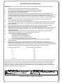
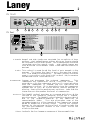
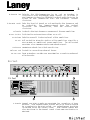
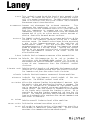
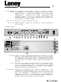
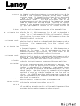
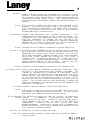
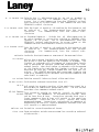
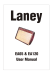
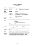
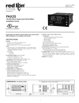
Laney
Richter Bass
Amplification
R1
R2
R3/R3H
R4/R4H
R5
User manual
IMPORTANT SAFETY INSTRUCTIONS
WARNING: When using electric products, basic cautions should always be followed, including the following.
1.
2.
3.
4.
5.
6.
7.
8.
9.
10.
11.
12.
13.
14.
15.
16.
17.
Read all safety and operating instructions before using this product
All safety and operating instructions should be retained for future reference
Obey all cautions in the Operating instructions and on the back of the unit
All operating instructions should be followed
This product should not be used near water, i.e. a bathtub, sink, swimming pool, wet basement, etc.
This product should be located so that its position does not interfere with its proper ventilation. It should not
be placed flat against a wall or placed in a built up enclosure that will impede the flow of cooling air.
This product should not be placed near a source of heat such as stove, radiator, or another heat producing
amplifier.
Connect only to a power supply of the type marked on the unit adjacent to the power supply cord.
Never break off the ground pin on a power supply cord.
Power supply cords should always be handled carefully. Never walk or place equipment on power supply
cords. Periodically check cords for cuts or signs of stress, especially at the plug and the point where the
chord exits the unit.
The power supply cord should be unplugged when the unit is to be unused for long periods of time.
If this product is to be mounted in an equipment rack, rear support should be provided.
Metal parts can be cleaned with a damp cloth. The vinyl covering used on some units can be cleaned with
a damp cloth or ammonia based household cleaner if necessary. Disconnect the unit from the power
supply before cleaning.
Care should be taken so that objects do not fall and liquids are not spilled into the unit through any
ventilation holes or openings. On no account place drinks on the unit.
A qualified service technician should check the unit if:
The power cord has been damaged
Anything has fallen or spilled into the unit
The unit does not appear to operate correctly
The unit has been dropped or the enclosure damaged.
The user should not attempt to service the equipment. All service work is done by a qualified
service technician.
Exposure to extremely high noise levels may cause a permanent hearing loss. Individuals vary
considerably in susceptibility to noise induced hearing loss, but nearly everyone will lose some hearing if
exposed to sufficiently intense noise for a sufficient time. The U.S. Government's Occupational Safety and
Health Administration (OSHA) has specified the following permissible noise level exposure.
Duration Per Day In Hours
Sound Level dBA, slow response
8
90
6
92
4
95
3
97
2
100
1½
102
1
105
½
110
¼ or less
115
According to OSHA, any exposure in excess of the above permissible limits could result in some hearing loss. Ear
plugs or protectors in the ear canals or over the ears must be worn when operating this amplification system in
order to prevent a permanent hearing loss if exposure exceeds the limits set forth above. To ensure against
potentially dangerous exposure to high sound pressure levels it is recommended that all persons exposed to
equipment capable of producing high sound pressure levels such as this amplification system be protected by
hearing protectors while this unit is in operation.
Lightning Bolt Symbol:
Exclamation Mark Symbol:
This symbol is used to alert the user to the presence
of dangerous voltages and the possible risk of
electric shock.
!
This symbol is used to alert the user to make special note of
important operating or maintenance instructions found in the
reference manual.
SAVE THESE INSTRUCTIONS
Laney
1
INTRODUCTION
Congratulations on your decision to purchase a Laney amplifier.
Laney products are designed with ease of operation as a primary objective, however to
ensure you derive the best from your new amplifier, it is important you take time to
read this user manual and to familiarise yourself with the control functions and
facilities available.
BEFORE SWITCHING ON
After unpacking your amplifier check that it is factory fitted with a three pin
'grounded' (or earthed) plug. Before plugging into the power supply ensure you are
connecting to a grounded earth outlet.
If you should wish to change the factory fitted plug yourself, ensure that the wiring
convention applicable to the country where the amplifier is to be used is strictly
conformed to.
As an example in the United Kingdom the cable colour code for
connections are as follows.
EARTH OR GROUND - GREEN/YELLOW
NEUTRAL - BLUE
LIVE - BROWN
This manual has been written for easy access of information. The front and rear
panels of each unit are graphically illustrated, with each control and feature
numbered. For a description of the function of each control feature, simply check
the number with the explanations adjacent to each panel.
Your Laney RICHTER bass amplifier has undergone a thorough two stage, pre-delivery
inspection, involving actual play testing, as well as burn in.
When you first receive your Laney RICHTER bass amp, follow these simple procedures:
(i) Ensure that the amplifier is set at the correct voltage for the country it is to
be used in.
(ii) Connect your instrument with a high quality shielded instrument cable. Use of
cheap cables will compromise the sound of your instrument and your amplifier.
Care of your Laney amplifier will prolong it's life.....and yours!.
Laney
2
R1 front
NORMAL
HIGH
3
4
5
6
4
7
8
2
1
COMP
9
INPUTS
GAIN
1
2
6
9
10
0
ON
- 0+
EQUALISATION
3
4
BASS
4
5
1
- 0+
4
5
5
FREQUENCY
LEVEL
6
7
PARA-MID
4
1
2
2
3 3
4
1K
100
1
2
3
4
5
5
- 0+
1
2
2
ENHANCE
3
350
1
2
8 3
1
ACTIVE
1
7
2
10
0
5
3
3
4
HORN
TREBLE
8
6
7
9
BASS AMPLIFIER
1
9
0
ACTIVE
R1
8
2
1
4
5
5
5
3
0
10
VOLUME
D.I.
10
11
POWER
POWER
R1 Rear
T2A L 115V
WARNING - TO REDUCE THE RISK OF FIRE OR ELECTRIC SHOCK
T1A L ~230V
DO NOT EXPOSE THIS APPLIANCE TO RAIN OR MOISTURE.
FUSE RATING & SUPPLY VOLTAGE. CAUTION - FOR CONTINUED PROTECTION AGAINST RISK OF FIRE
REPLACE ONLY WITH SAME TYPE AND RATED FUSE.
CAUTION - TO REDUCE THE RISK OF ELECTRIC SHOCK DO NOT
REMOVE COVERS.NO USER SERVICEABLE PARTS INSIDE. REFER
SERVICING TO QUALIFIED PERSONNEL ONLY.
WARNING - THIS EQUIPMENT MUST BE EARTHED.
ATTENTION - REMPLACER LE FUSIBLE SEULEMENT PAR LE MEME
TYPE ET LE MEME CALIBRE.
AVIS - RISQUE DE CHOC ELECTRIQUE - NE PAS OUVRIR.
ATTENTION - DEBRANCHER LE CORDON D’ALIMENTATION
MAXIMUM POWER CONSUMPTION AVANT TOUTE INTERVENTION.
120 WATTS ~50/60 HZ
CAUTION
RISK OF ELECTRIC SHOCK DO NOT OPEN
FX Send
Head Phones
TunerOut
!
FX Return
SERIAL
NUMBER
Designed And Assembled in the UK by BLT Industries LTD.
12
13
14
1.Inputs: Normal and High inputs are provided for connection of bass
guitars. High output basses, either Active or Passive should
be connected via the High socket. Low output basses should be
connected using the normal input. High output basses may
also be placed in the Normal input if pre-amp overloading is
desired.
2.Gain: This control is used to set the level of gain present in the
pre-amp. The higher the level of gain, the more the signal
will clip producing distortion. The GAIN control should be
used in conjunction with the VOLUME control (10) to produce
the desired signal characteristics.
3.Compressor: Engages
and disengages the on-board cpmpressor.
This
compresses the input-signal giving a punchier sound.
In
association with the compressor are two LED s,one indicating
that the compressor is engaged and one indicating the
compressor is active. It is possible to have the compressor
engaged but it only be active during certian periods of
playing - typically the most dynamic sections. Note that the
higher the gain the greater the level of compression.
4.Enhance: The ENHANCE control provides an increased definition at the
low-end of the frequency spectrum giving you a tighter,
punchier sound. The ENHANCE control does this by providing a
dip in the frequency-response of the amplifier at
approximately 200hz.
This dip eliminates some of the
secondary-harmonics of the important low-frequencies around
40-80 Hz producing a thicker sound. Turning the control
through to its maximum has the effect of boosting both the
low and high-frequency content of the signal whilst not
effecting the mids.
5.Bass: Controls the low-frequency response of the pre-amplifier.
Laney
3
6.Paramid frq: Selects
the MID-frequencies to be cut or boosted in
conjunction with the PARAMID GAIN control (7). To access LO
mid-frequencies turn the FREQUENCY control anticlockwise, to
access HI mid frequencies turn the FREQUENCY control
clockwise.
7.Paramid Level: Sets the level of boost or cut applied to the frequency set
by control(6).
clockwise. For
clockwise.
For frequency-boost turn the control
frequency-cut, turn the control anti-
8.Treble: Controls the high-frequency response of the pre-amplifier.
9.Horn Switch: Switches the on-board horn either on or off.
10.Volume: Sets the overall listening level of the amplifier.
11.D.I: XLR socket for direct-injection of the amplifier signal to a
mixing-desk or additional power-amplifier. The XLR socket
provides a low-impedance balanced output-signal.
12.Phones: Headphone output for silent practicing.
13.Tuner out: Socket for connecting external tuner.
14.FX Loop: Send and return sockets are provided for connecting external
effects-units.
R2 Front
NORMAL
HIGH
3
4
5
6
7
8
2
1
COMP
9
INPUTS
GAIN
1
2
5
6
3
7
- 0+
2
9
10
0
EQUALISATION
350
1
4
3
ENHANCE
BASS
4
5
4
5
5
LEVEL
PARA-MID
6
- 0+
7
4
1
2
2
3 3
4
1K
100
1
2
3
4
5
5
1
2
3
FREQUENCY
ON
- 0+
1
2
8 3
1
ACTIVE
1
2
10
0
R2 Rear
4
5
6
3
7
8
3 2
4
4
5
5
4
1
LIMITER
PRESENCE
8
9
7
8
1
9
TREBLE
6
2
10
0
5
3
10
BASS AMPLIFIER
1
HORN
9
0
ACTIVE
R2
0
10
VOLUME
11
ACTIVE
12
D.I.
POWER
POWER
13
16
T5A L 115V
WARNING - TO REDUCE THE RISK OF FIRE OR ELECTRIC SHOCK
T2A L ~230V
DO NOT EXPOSE THIS APPLIANCE TO RAIN OR MOISTURE.
FUSE RATING & SUPPLY VOLTAGE.CAUTION - FOR CONTINUED PROTECTION AGAINST RISK OF
FIRE REPLACE ONLY WITH SAME TYPE AND RATED FUSE.
CAUTION - TO REDUCE THE RISK OF ELECTRIC SHOCK DO NOT
REMOVE COVERS.NO USER SERVICEABLE PARTS INSIDE. REFER
SERVICING TO QUALIFIED PERSONNEL ONLY.
WARNING - THIS EQUIPMENT MUST BE EARTHED.
ATTENTION - REMPLACER LE FUSIBLE SEULEMENT PAR LE
MEME TYPE ET LE MEME CALIBRE.
AVIS - RISQUE DE CHOC ELECTRIQUE - NE PAS OUVRIR.
ATTENTION - DEBRANCHER LE CORDON
Extension
’ALIMENTATION AVANT TOUTE INTERVENTION.
Loudspeaker
MAXIMUM POWER CONSUMPTION
240 WATTS ~50/60 HZ
CAUTION
RISK OF ELECTRIC SHOCK DO NOT OPEN
SERIAL
NUMBER
Designed And Assembled in the UK by BLT Industries LTD.
!
FXSend
FXReturn
8 OHM
MINIMUM
IMPEDANCE
REFER TO USER MANUAL
FOR LOUDSPEAKER CONNECTIONS
14
TunerOut
15
1.Inputs: Normal and High inputs are provided for connection of bass
guitars. High output basses, either Active or Passive should
be connected via the High socket. Low output basses should be
connected using the normal input. High output basses may
also be placed in the Normal input if pre-amp overloading is
desired.
Laney
4
2.Gain: This control is used to set the level of gain present in the
pre-amp. The higher the level of gain, the more the signal
will clip producing distortion. The GAIN control should be
used in conjunction with the VOLUME control (10) to produce
the desired signal characteristics.
3.Compressor: Engages
and disengages the on-board comprssor.
This
compresses the input-signal giving a punchier sound.
In
association with the compressor are two LED s,one indicating
that the compressor is engaged and one indicating the
compressor is active. It is possible to have the compressor
engaged but it only be active during certian periods of
playing - typically the most dynamic sections.
4.Enhance: The ENHANCE control provides an increased definition at the
low-end of the frequency spectrum giving you a tighter,
punchier sound. The ENHANCE control does this by providing
a dip in the frequency-response of the amplifier at
approximately 200hz.
This dip eliminates some of the
secondary-harmonics of the important low-frequencies around
40-80 Hz producing a thicker sound. Turning the control
through to its maximum has the effect of boosting both the
low and high-frequency content of the signal whilst not
effecting the mids.
5.Bass: Controls the low-frequency response of the pre-amplifier
6.Paramid frq: Selects
the MID-frequencies to be cut or boosted in
conjunction with the PARAMID GAIN control (7). To access LO
mid-frequencies turn the FREQUENCY control anticlockwise, to
access HI mid frequencies turn the FREQUENCY control
clockwise.
7.Paramid Level: Sets the level of boost or cut applied to the frequency set by
control(6). For frequency-boost turn the control clockwise.
For frequency-cut, turn the control anti-clockwise.
8.Treble: Controls the high-frequency response of the pre-amplifier.
9.Presence: Controls
the high-frequency signal-content of the preamplifier. The PRESENCE control is set at 3K.
10.Limiter: Allows the on-board limiter to be defeated if desired.
With
the switch in the out position the limiter is engaged. The
LIMITER is automatically triggered at high-output levels
and is designed to prevent power-amp distortion at highoutput levels. When the limiter is autpmatically triggered
an LED lights up to indicate the limiter is active. It is
possible to have the limiter engaged but not have the LED
active. The LIMITER monitors both power-amp clipping and
load so it automatically registers the cabinet-impedance and
sets itself accordingly.
11. Volume: Sets the overall listening level of the amplifier.
12.Horn switch: Switches the on-board horn either on or off.
13.D.I: XLR socket for direct-injection of the amplifier signal to a
mixing-desk or additional power-amplifier. The XLR socket
provides a low-impedance balanced output-signal.
Laney
5
14.Ext Speaker This socket should be used to connect an extension-cabinet.
socket: The impedance of the extension-cabinet must not be less
than 8 Ohms.
Connecting cabinets that have a lower
impedance than 8 Ohms will result in the amplifier
overheating .
Continual use in this
manner may cause
permanent damage. Connecting a cabinet with an impedance of
greater than 8 Ohms will cause no damage to the amplifier but
will result in a reduced output.
15.Tuner out: Socket for connecting external tuner.
16.FX Loop: Send and return sockets are provided for connecting external
effects-units..
R3/R3H Front
NORMAL
HIGH
3
4
5
6
4
7
8
2
1
COMP
9
INPUTS
GAIN
1
2
6
3
ON
- 0+
9
1
3
5
1K
100
BASS
4
5
1K5
1
3
5
1
4K
- 0+
4
5
5
LEVEL
FREQUENCY
LO PARA-MID
HI PARA-MID
6
7
8
LEVEL
9
4
1
2
2
3 3
4
400
1
2
3
4
5
- 0+
2
2
4
FREQUENCY
ENHANCE
1
3
4
5
- 0+
2
2
4
10
EQUALISATION
350
1
2
8 3
2
0
ACTIVE
1
7
1
10
0
5
3
3
4
LIMITER
10
7
8
2
ACTIVE
11
R3
BASS AMPLIFIER
1
HORN
9
0
5
TREBLE
6
1
4
5
5
3
0
10
VOLUME
12
ACTIVE
13
D.I.
POWER
POWER
14
R3 Rear
T5A L 115V
WARNING - TO REDUCE THE RISK OF FIRE OR ELECTRIC SHOCK
DO NOT EXPOSE THIS APPLIANCE TO RAIN OR MOISTURE.
T2A L ~230V
CAUTION - FOR CONTINUED PROTECTION AGAINST RISK OF
FUSE RATING & SUPPLY VOLTAGE.FIRE
REPLACE ONLY WITH SAME TYPE AND RATED FUSE.
CAUTION - TO REDUCE THE RISK OF ELECTRIC SHOCK DO NOT
REMOVE COVERS.NO USER SERVICEABLE PARTS INSIDE. REFER
SERVICING TO QUALIFIED PERSONNEL ONLY.
WARNING - THIS EQUIPMENT MUST BE EARTHED.
ATTENTION - REMPLACER LE FUSIBLE SEULEMENT PAR LE
MEME TYPE ET LE MEME CALIBRE.
AVIS - RISQUE DE CHOC ELECTRIQUE - NE PAS OUVRIR.
ATTENTION - DEBRANCHER LE CORDON D’ALIMENTATION
AVANT TOUTE INTERVENTION.
MAXIMUM POWER CONSUMPTION
CAUTION
RISK OF ELECTRIC SHOCK DO NOT OPEN
!
300 WATTS ~50/60 HZ
SERIAL
NUMBER
Designed And Assembled in the UK by BLT Industries LTD.
FXSend
Extension
Loudspeaker
FXReturn
8 OHM
MINIMUM
IMPEDANCE
REFER TO USER MANUAL
FOR LOUDSPEAKER CONNECTIONS
15
1.Inputs: Normal and High inputs are provided for connection of bass
guitars. High output basses, either Active or Passive should
be connected via the High socket. Low output basses should be
connected using the normal input. High output basses may
also be placed in the Normal input if pre-amp overloading is
desired.
2.Gain: This control is used to set the level of gain present in the
pre-amp. The higher the level of gain, the more the signal
will clip producing distortion. The GAIN control should be
used in conjunction with the VOLUME control (12) to produce
the desired signal characteristics.
3.Compressor: Engages
17
and disengages the on-board compressor.
This
compresses the input-signal giving a punchier sound.
In
association with the compressor are two LED s,one indicating
that the compressor is engaged and one indicating the
compressor is active. It is possible to have the compressor
engaged but it only be active during certain periods of
playing - typically the most dynamic sections.
TunerOut
16
Laney
6
4.Enhance: The ENHANCE control provides an increased definition at the
low-end of the frequency spectrum giving you a tighter,
punchier sound. The ENHANCE control does this by providing
a dip in the frequency-response of the amplifier at
approximately 200hz.
This dip eliminates some of the
secondary-harmonics of the important low-frequencies around
40-80 Hz producing a thicker sound. Turning the control
through to its maximum has the effect of boosting both the
low and high-frequency content of the signal whilst not
effecting the mids.
5.Bass: Controls the low-frequency response of the pre-amplifier
6. Lo Paramid frq: Selects the LO MID-frequencies to be cut or boosted in
conjunction with the
LO PARAMID LEVEL control (7). To
access low LO mid-frequencies turn the FREQUENCY control
anticlockwise, to access higher LO MID frequencies turn the
FREQUENCY control clockwise
7.Lo Paramid Level: Sets the level of boost or cut applied to the frequency set by
8. Hi Paramid frq:
9.Lo Paramid Level:
10.Treble:
11.Limiter:
12. Volume:
13.Horn switch:
14.D.I:
control (6).
For frequency-boost turn the control
clockwise.
For frequency-cut, turn the control anticlockwise
Hi Paramid Frequency : Selects the HI MID-frequencies to
be cut or boosted in conjunction with the Hi PARAMID LEVEL
control (9). To access
low Hi mid-frequencies turn the
FREQUENCY control anticlockwise, to access higher Hi MID
frequencies turn the FREQUENCY control clockwise
Sets the level of boost or cut applied to the frequency set by
control 8. For frequency-boost turn the control clockwise.
For frequency-cut, turn the control anti-clockwise
Controls the high-frequency response of the pre-amplifier.
Allows the on-board limiter to be defeated if desired. With
the switch in the out position the limiter is engaged. The
limiter is automatically triggered at high-output levels
and is designed to prevent power-amp distortion at highoutput levels. When the limiter is autpmatically triggered
an LED lights up to indicate the limiter is active. It is
possible to have the limiter engaged but not have the LED
active. The LIMITER monitors both power-amp clipping and
load so it automatically registers the cabinet-impedance and
sets itself accordingly.
Sets the overall listening level of the amplifier.
Switches the on-board horn either on or off.
XLR socket for direct-injection of the amplifier signal to a
mixing-desk or additional power-amplifier. The XLR socket
provides a balanced low-impedance output-signal.
Laney
7
15.Ext Speaker This socket(s) should be used to connect an extensionsocket: cabinet.
The impedance of the extension-cabinet must
not be less thean 8 Ohmsfor the R3, or for the R3H a Minimum 4
Ohms. Connecting cabinets that have a lower impedance than
8 Ohms will result in the amplifier overheating. Continual
use in this manner may cause permanent damage. Connecting
a cabinet with an impedance of greater than 8 Ohms will cause
no damage to the amplifier but will result in a reduced
output.
16.Tuner out:
Socket for connecting external tuner.
17.FX Loop:
Send and return sockets are provided for connecting external
effects-units..
R3H Rear
T5A L 115V
WARNING - TO REDUCE THE RISK OF FIRE OR ELECTRIC SHOCK
T2A L ~230V
DO NOT EXPOSE THIS APPLIANCE TO RAIN OR MOISTURE.
FUSE RATING & SUPPLY VOLTAGE.CAUTION - FOR CONTINUED PROTECTION AGAINST RISK OF
FIRE REPLACE ONLY WITH SAME TYPE AND RATED FUSE.
CAUTION - TO REDUCE THE RISK OF ELECTRIC SHOCK DO NOT
REMOVE COVERS.NO USER SERVICEABLE PARTS INSIDE. REFER
SERVICING TO QUALIFIED PERSONNEL ONLY.
WARNING - THIS EQUIPMENT MUST BE EARTHED.
ATTENTION - REMPLACER LE FUSIBLE SEULEMENT PAR LE
MEME TYPE ET LE MEME CALIBRE.
AVIS - RISQUE DE CHOC ELECTRIQUE - NE PAS OUVRIR.
ATTENTION - DEBRANCHER LE CORDON D’ALIMENTATION
AVANT TOUTE INTERVENTION.
MAXIMUM POWER CONSUMPTION
CAUTION
RISK OF ELECTRIC SHOCK DO NOT OPEN
!
300 WATTS ~50/60 HZ
SERIAL
NUMBER
17
FXSend
Loudspeakers
FXReturn
REFER TO USER MANUAL FOR RECOMMENDED
LOUDSPEAKER CONNECTIONS
TunerOut
Designed And Assembled in the UK by BLT Industries LTD.
4 OHM TOTAL MINIMUM IMPEDANCE
15
16
R4/R4H Front
EQUALISATION
NORMAL
HIGH
3
5
4
6
4
7
8
2
1
9
INPUTS
GAIN
1
2
R4/R4H Rear
6
3
7
ON
- 0+
1
2
9
10
+15
+15
0dB
0dB
3
4
-15
-15
- 0+
2
LIMITER
3
3
40Hz 80Hz 160Hz 400Hz 800Hz 2KHz 6KHz
TREBLE
4
5
6
7
6
3
7
BASS AMPLIFIER
1
9
0
10
0
ACTIVE
R4H
8
1
4
BASS
5
2
5
5
ENHANCE
3
4
1
4
4
5
5
1
2
2
8 3
0
ACTIVE
1
2
1
10
0
T6.3A L 115V
T3.15A L ~230V
COMP
5
VOLUME
D.I.
9
10
8
POWER
POWER
11
LOUDSPEAKERS
FUSE RATING & SUPPLY VOLTAGE. CAUTION - REFER TO
USERS MANUAL FOR
RECOMMENDED
SPEAKER CONNECTIONS.
13
CAUTION
RISK OF ELECTRIC SHOCK DO NOT OPEN
!
Designed And Assembled in the UK by BLT Industries LTD.
A TOTAL LOAD OF NO LESS
THAN 4 OHMS MAY BE
CONNECTED AT ANY
TIME.
MAXIMUM POWER CONSUMPTION CLASS 2 WIRING MAY BE USED
450 WATTS ~50/60 HZ
CAUTION TO REDUCE THE RISK OF ELECTRIC SHOCK DO NOT
REMOVE COVERS. NO USER SERVICEABLE PARTS INSIDE.
REFER SERVICING TO QUALIFIED PERSONNEL ONLY.
WARNING -TO REDUCE THE RISK OF FIRE OR ELECTRIC SHOCK
DO NOT EXPOSE THIS APPLIANCE TO RAIN OR MOISTURE.
CAUTION-FOR CONTINUED PROTECTION AGAINST RISK OF FIRE
REPLACE ONLY WITH SAME TYPE AND RATED FUSE
WARNING - THIS EQUIPMENT MUST BE EARTHED.
ATTENTION - SE REFERER AU MANUEL D’UTILISATION POUR LA CONNECTION
HAUT-PARLEURS.
AVIS - RISQUE DE CHOC ELECTRIQUE NE PAS OUVRIR.
ATTENTION - REMPLACER LE FUSIBLE SEULEMENT PAR LE MEME TYPE ET LE
MEME CALIBRE.
ATTENTION - DEBRANCHER LE CORDON D’ALIMENTATION AVANT TOUTE INTERVENTION.
ATTENTION - REFROIDI PAR VENTILATEUR. NE PAS OBSTRUER LES GRILLES
D’AERATION ET DE VENTILATION.
SERIAL NUMBER
FXSend
FXReturn
TunerOut
CAUTION - FAN COOLED. DO NOT OBSTRUCT THE FAN OR VENT APERTURES.
12
Laney
8
1.Inputs: Normal and High inputs are provided for connection of bass
guitars. High output basses, either Active or Passive should
be connected via the High socket. Low output basses should be
connected using the normal input. High output basses may
also be placed in the Normal input if pre-amp overloading is
desired.
2.Gain: This control is used to set the level of gain present in the
pre-amp. The higher the level of gain, the more the signal
will clip producing distortion. The GAIN control should be
used in conjunction with the VOLUME control (9) to produce
the desired signal characteristics.
3.Compressor: Engages
and disengages the on-board compressor.
This
compresses the input-signal giving a punchier sound.
In
association with the compressor are two LED s,one indicating
that the compressor is engaged and one indicating the
compressor is active. It is possible to have the compressor
engaged but it only be active during certian periods of
playing - typically the most dynamic sections.
5.Bass: Controls the low-frequency response of the pre-amplifier
6.Graphic EQ: The 7-band onboard GRAPHIC-EQ allows extensive tonal-shaping
to be achieved. With the sliders along the centre-line the
GRAPHIC-EQ will exert a flat signal- response it is at this
point that individual frequency-bands can be cut or boosted.
Moving the slider beneath the centre-line will incur a
frequency-cut
conversely, pushing the slider above the
centre-line facilitates frequency-boost. As a general rule,
avoid extreme settings of the sliders:
try to set the
GRAPHIC with as little cut or boost as possible.
7.Treble: Controls the high-frequency response of the pre-amplifier.
8.Limiter Switch: Allows the on-board LIMITER to be defeated if desired.
With
the switch in the out position the limiter is engaged. The
limiter is automatically triggered at high-output levels
and is designed to prevent power-amp distortion at highoutput levels. When the limiter is autpmatically triggered
an LED lights up to indicate the limiter is active. It is
possible to have the limiter engaged but not have the LED
active. The limiter monitors both power-amp clipping and
load so it automatically registers the cabinet-impedance and
sets itself accordingly.
9.Volume: Sets the overall listening level of the amplifier.
10.D.I: XLR socket for direct-injection of the amplifier signal to a
mixing-desk or additional power-amplifier. The XLR socket
provides a low-impedance balanced output-signal.
11.Ext Speaker This socket(s) should be used to connect an extensionsocket: cabinet.
The impedance of the extension-cabinet must
not be less than 8 Ohms. Connecting cabinets that have a
lower impedance than 8 Ohms will result in the amplifier
overheating.
Continual use in this
manner may cause
permanent damage. Connecting a cabinet with an impedance of
greater than 8 Ohms will cause no damage to the amplifier but
will result in a reduced output.
12.Tuner out: Socket for connecting external tuner.
13.FX Loop: Send and return sockets are provided for connecting external
effects-units..
Laney
9
R5 Front
NORMAL
HIGH
3
4
5
6
4
7
8
2
1
COMP
9
INPUTS
GAIN
1
2
ON
- 0+
9
10
EQUALISATION
350
1
2
1
3
4
5
1K
100
BASS
4
5
3
1K5
1
3
5
1
4K
- 0+
4
2
5
5
LEVEL
FREQUENCY
LO PARA-MID
HI PARA-MID
6
7
8
LEVEL
9
3
4
LIMITER
TREBLE
10
7
8
2
ACTIVE
11
BASS AMPLIFIER
1
HORN
9
0
10
0
5
R5
6
3
1
4
5
5
4
1
2
3 3
4
400
1
2
3
4
5
- 0+
2
2
4
FREQUENCY
ENHANCE
1
3
4
5
- 0+
2
2
8 3
2
0
ACTIVE
1
7
R5 Rear
T6.3A L
6
1
10
0
5
3
VOLUME
12
ACTIVE
13
D.I.
POWER
POWER
14
15
17
115V
CAUTION TO REDUCE THE RISK OF ELECTRIC SHOCK DO NOT
T3.15A L ~230V
REMOVE COVERS. NO USER SERVICEABLE PARTS INSIDE.
FUSE RATING & SUPPLY VOLTAGE. REFER SERVICING TO QUALIFIED PERSONNEL ONLY.
WARNING -TO REDUCE THE RISK OF FIRE OR ELECTRIC SHOCK
DO NOT EXPOSE THIS APPLIANCE TO RAIN OR MOISTURE.
C
-F
MAXIMUM POWER CONSUMPTION
450 WATTS ~50/60 HZ
AUTION OR CONTINUED PROTECTION AGAINST RISK OF FIRE
REPLACE ONLY WITH SAME TYPE AND RATED FUSE
WARNING - THIS EQUIPMENT MUST BE EARTHED.
ATTENTION - SE REFERER AU MANUEL D’UTILISATION POUR
LA CONNECTION HAUT-PARLEURS.
AVIS - RISQUE DE CHOC ELECTRIQUE NE PAS OUVRIR.
ATTENTION - REMPLACER LE FUSIBLE SEULEMENT
PAR LE MEME TYPE ET LE MEME CALIBRE.
ATTENTION - DEBRANCHER LE CORDON D’ALIMENTATION AVANT
TOUTE INTERVENTION.
CAUTION
RISK OF ELECTRIC SHOCK DO NOT OPEN
EXTENSION LOUDSPEAKER
!
SERIAL NUMBER
Designed And Assembled in the UK by BLT Industries LTD.
8 OHMS MINIMUM
LOUDSPEAKER IMPEDANCE.
CAUTION - REFER TO USERS
FXSend
MANUAL FOR RECOMMENDED
SPEAKER CONNECTIONS.
CLASS 2 WIRING MAY BE USED
FXReturn
TunerOut
CAUTION - FAN COOLED. DO NOT OBSTRUCT THE FAN OR VENT APERTURES.
17
1.Inputs: Normal and High inputs are provided for connection of bass
guitars. High output basses, either Active or Passive should
be connected via the High socket. Low output basses should be
connected using the normal input. High output basses may
also be placed in the Normal input if pre-amp overloading is
desired.
2.Gain: This control is used to set the level of gain present in the
pre-amp. The higher the level of gain, the more the signal
will clip producing distortion. The GAIN control should be
used in conjunction with the VOLUME control (12) to produce
the desired signal characteristics.
3.Compressor: Engages
and disengages the on-board compressor.
This
compresses the input-signal giving a punchier sound.
In
association with the compressor are two LED s,one indicating
that the compressor is engaged and one indicating the
compressor is active. It is possible to have the compressor
engaged but it only be active during certian periods of
playing - typically the most dynamic sections.
4.Enhance: The ENHANCE control provides an increased definition at the
low-end of the frequency spectrum giving you a tighter,
punchier sound. The ENHANCE control does this by providing
a dip in the frequency-response of the amplifier at
approximately 200hz.
This dip eliminates some of the
secondary-harmonics of the important low-frequencies around
40-80 Hz producing a thicker sound. Turning the control
through to its maximum has the effect of boosting both the
low and high-frequency content of the signal whilst not
effecting the mids.
5.Bass: Controls the low-frequency response of the pre-amplifier
Laney
10
6. Lo Paramid frq: Selects the LO MID-frequencies to be cut or boosted in
conjunction with the
LO PARAMID LEVEL control (7). To
access low LO mid-frequencies turn the FREQUENCY control
anticlockwise, to access higher LO MID frequencies turn the
FREQUENCY control clockwise
7.Lo Paramid Level: Sets the level of boost or cut applied to the frequency set
by control 6.
For frequency-boost turn the control
clockwise.
For frequency-cut, turn the control anticlockwise
8. Hi Paramid frq: Hi Paramid Frequency :
Selects the HI MID-frequencies to
be cut or boosted in conjunction with the Hi PARAMID LEVEL
control (9). To access
low Hi mid-frequencies turn the
FREQUENCY control anticlockwise, to access higher Hi MID
frequencies turn the FREQUENCY control clockwise
9.Lo Paramid Level: Sets the level of boost or cut applied to the frequency set
by control 8.
For frequency-boost turn the control
clockwise.
For frequency-cut, turn the control anticlockwise
10.Treble: Controls the high-frequency response of the pre-amplifier.
11.Limiter: Allows the on-board limiter to be defeated if desired.
With
the switch in the out position the limiter is engaged. The
limiter is automatically triggered at high-output levels
and is designed to prevent power-amp distortion at highoutput levels. When the limiter is autpmatically triggered
an LED lights up to indicate the limiter is active. It is
possible to have the limiter engaged but not have the LED
active. The LIMITER monitors both power-amp clipping and
load so it automatically registers the cabinet-impedance and
sets itself accordingly.
12. Volume: Sets the overall listening level of the amplifier.
13.Horn switch: Switches the on-board horn either on or off.
14.D.I: XLR socket for direct-injection of the amplifier signal to a
mixing-desk or additional power-amplifier.
provides a low-impedance output-signal.
The XLR socket
15.Ext Speaker This socket(s) should be used to connect an extensionsocket: cabinet.
The impedance of the extension-cabinet must
not be less than 8 Ohms. Connecting cabinets that have a
lower impedance than 8 Ohms will result in the amplifier
overheating . Continual use in this
manner may cause
permanent damage. Connecting a cabinet with an impedance of
greater than 8 Ohms will cause no damage to the amplifier but
will result in a reduced output.
16.Tuner out: Socket for connecting external tuner.
17.FX Loop: Send and return sockets are provided for connecting external
effects-units..
Laney
11
R1
R2
R3
R3H
R4
R4H
R5
Power Output
65W
120W
165W
165W
300W
300W
300W
Maximum Power
Consumption
50/60Hz
120W
240W
300W
300W
450W
450W
450W
Input Impedance Normal/Hi
1M Ohm
1M Ohm
1M Ohm
1M Ohm
1M Ohm
1M Ohm
1M Ohm
Input Sensitivity Norma/Hi
20/40mV
10/20mV
12/24mV
12/24mV
12/24mV
12/24mV
12/24mV
FX Loop Level
(Nominal)
700mV
800mV
800mV
800mV
800mV
800mV
800mV
Minimum Ext.Speaker
Impedance
n/a
8 Ohms
8 Ohms
4 Ohms* 8 Ohms
eg 2x8 Ohms
or 1x4 Ohms
4 Ohms*
8 Ohms
eg 2x8 Ohms
or 1x4 Ohms
n/a
60 Watts
80 Watts
165 Watts*
300 Watts*
Recommended
Minimum Extension
Speaker Power Rating
Recommended Richter
Extension Cabinets
150 Watts (4 Ohms) 150 Watts(4 Ohms)
100 watts (8 Ohms) 150 Watts(8 Ohms)
n/a
R115
R410
or R115
R410
R410
& R115
or R115
or 2xR410
R410
R410
& R115
or R115
or 2xR410
Laney Amplification
Newlyn Road, Cradley Heath, West Midlands
B64 6BE
United Kingdom.
WWW.laney.co.uk
In the interest of on going product development Laney reserves the right to amend specifications without prior notification