1
REVISIONS
%Themanualnumberisgivenonthebottom
Print Date
'Manual Number
May, 1990
I6 (NA) 66236-A
May, 1993
Jul.,1993
I6 (NA) 66236-6
IB (NA) 66236-C
I
I
left of the back cover.
Revision
First edition
[
I
1
Addition
Section 3.2.2. 3.2.3. 3.3.4.. 3.7,. 4.2.5
Correction
CONTENTS, Section 2.1, 2.2, 3.2.4,3.2.5,3.3.1, 3.3.2, 3.3.5,3.4.1,3.4.2,3.4.3,
3.6,
4.2.2, 4.2.3, 5.1.1, APP.1
I
I
I
Addition of models
AJ35TBl-l6D, AJ35T62-16D,
AJ35TC1-32D,
AJ35T61-16T,
AJ35T62-16T,
AJ35TC1-32T,AJ35TC1-32DT
Correction
CONTENTS, Section 1, 2.1,2.2,4.2,
4.2.1, 5.1, 5.1.1 t o 5.1.4
Addition
3.8,3.8.1
to 3.8.7, 4.1.3, APP.1-(5) t o (7)
I
I
I
I
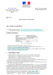
INTRODUCTION
Thank you for choosing the Mitsubishi MELSEC-A Series of General Purpose Programmable
Controllers. Please read this manual carefully so that the equipment is used to its optimum.
A copyofthis
manual should beforwardedtothe
end User.
IB iNLY E623F-A
.
.
1
CONTEYTS
.
. . .
c
.
INTRQDUCrlON ....................................................................................................
.
. .
.
2. NOTES ON SELECTING
UWTS
THEI/O
. .
.
.
..........................................
3.3
3.4
3.5
3.6
3.7
.
;'.................. 2-1-2-8
.
.
3. SPECIFICATIONS..........................................................................................
3.1
3.2
1.1
3-1 -3-27
Specifications Common to the
A2CI/O Units ............................................................
Input Units .........................................................................................................
3.2.1 TypeAXllClOOVACinputunit(32points. 6mA) ...........................................
3.2.2 Type AX21C 2OOVAC input unit (32 points. 5mA) ...........................................
3-1
3-2
3-2
3-3
3.2.3 Type AX31C DC/AC input unit (32 points. 4mA/8.5mA) .................................... 3-4
3.2.4 TypeAX41C 12/24VDC inputunit (sink loading. 32 points. 3mAnmA) ............... 3-5
3.2.5 Type AX81C12/24VDC
inputunit(sinkkource
loading.
32 points. 3mAnmA) .................................................................................
3-6
Output Units....................................................................................................... 3-7
3.3.1 Type AY13C relay output unit (12V DC/llOV AC. 32 points. 0.5A) ...................... 3-7
3.3.2 Type AY23C triac output unit (100-24OV AC. 32 points. 0.3A) ............................ 3-8
3.3.3 Type AY51C transistoroutputunit(sink
loading. 12/24VDC.
32 points. 0.3A) ......................................................................................... 3-9
3.3.4 Type AY61CE transistoroutputunit(source
loading. 5 to 24VDC.
32 points.1.OA) .......................................................................................
3-10
3.3.5 Type AY81C transistor output unit(24V DC. 32 points. 0.5A) ..........................
3-11
I/() Units .......................................................................................................... 3-12
3.4.1 Type AXlOYlOC I/O unit (lOOV AC. input: 16 points. relay output:
16 points) ............................................................................................... 3-12
3.4.2 Type AX40YlOC I/O unit (12/24V DC. input: 16 points. relay output:
16 points) ...............................................................................................
3-13
input: 16 points. output:
triac
3.4.3 Type AX10Y22C I/O unit AC.
( 1OOV
16 points) ........................
....................................................................... 3-1 4
3.4.4 Type AX40Y50C I/O unit ( 12/24VDC. input: 16 points. transistor
output: 16 points) ..................................................................................... 3-15
3.4.5 Type AX80YlOC I/O unit ( 12/24VDC, input: 16 points, relay output:
16 points) ............................................................................................... 3-16
3.4.6 Type AX80Y80C I/O unit (12/24V DC. input: 16 points. transistor
output: 16 points) ....................................................................................
3-17
power SupplyUnit(A66pC) ................................................................................
3-18
DIN Rail Adapter (ASDINlC)................................................................................ 3-20
Common TerminalBlock (AZCCOM-TB) ...............................................................
3-20
c
I
rn
Lu
5.1
5.2
.
APPENDIX
..................................................................................................
APPENDIX 1 EXTERNAL DIMENSION DIAGRAM
......
._._I
.....
.
.
.
_. ...... -
....
APP-1 -APP-7
.......................................................
...
-.
....
-..-.
APP-1
1. INTRODUCTION
/MELSEC
\
1. WTRODUCTION
This manual describes handling instructions and specifications
for
the A2C I/O unit,remoteterminalblock
I/O unit andremote
connector I/O unit (to be referred to as MINI remote I/O in this
manual) to be used with the AZCCPU unit (to be referred to as
A2CCPU inthis manual).
The MINI remote I/O is a simple I/O unit of baseless building block
type which connects itselfto the A2CCPU with twisted pair cables
without a base unit. The maximum length of twisted pair cables
allowed for this connection
is 100 meters (3.28 f?).
The MINI remoteI/O can be mounted easily to the DIN rail usingan
optional DIN railadapter.
The MINIremote I/O can be used as the I/O moduleforthe
MELSECNET/MINI-S3data
link system (to be referred to as
MINK33link in this manual).
2. NOTES ON SELECTING THE I/O UNITS
2. NOTES ON SELECTINGTHE
/MELSEC
I10 UNITS
2.1 Modulesthat can Control the MINI Remote I/O Unit
Modules thatcan control the MINI remote I/O are as shown below.
A2CCPU (C24)
AJ71 PT32-S3 (AJ71PT32)
A1 SJ71PT32-S3
A52GCPU (T21B)
POINT
1
I
Since an A2C It0 unit, remote terminal block I/O unit or
remote connector unit is aremote I10 module for the
twisted pair data link, cable connection can be made only
withtwisted pair
cables.
L
I
IS (NA) €6236C
2. NOTES ON SELECTING THE I/O UNITS
2.2 Notes on Selecting the I10 Units
. ',
3 .
.,
(1) Triac .output- units should be used instead of relay contact
output units when:
0 The outpubs are being switchedveryfrequently.
0 A large inductive load isbeingswitched.
0 Aninductiveloadwith
a lowpower factorisbeing
switched.
The life ofa relay switching any of the above conditions will be
substantially reduced.
,
(2) The ON time and OFF time for any inductive load switched by
an output unit must be more than one second.
43). Bsware of rush-currents whena transistor output unitof which
.mximum Load current is 0.3 Ais used to switch a load
incorporating a DC/DC .converter (e.g. a timer or counter).
Either connect a resistive or inductive load in series with the
load or use an output unit of which maximum load current is
large.
output
unit
!?e?;
L
q
Inductance Load
output
unit
(4) Since overload protection is not provided,
an external fastblow'fuse should be used at each point where fuse protection
isrequired.
The following external fast-blow fuses are recommended.
AC : HP fuse
GP fuse
DC : MP fuse
2. NOTES ON SELECTING THE I/O UNITS
POINT
I
The following versions ace applicable to the I/O modules
in this manual.
I
AX40Y 1OC
I
AX80YlOC
Version J or later
Version C or later
I
Name plate
I
DATE 21OH
-t/
Date ofmanufacture
[Changed contents]
kern
I
Old version
Rated switchingDC 24V
current
lcurrent valueAC 240V
(cos# =1) ola%
(resistance
d:/
per point)
24V DC
simultaneousAC
240V
(cos# =1)
4Ncommon
I
I
200V AC
240V AC 0.3A lcos # =0.7)
200V AC
240V
AC
Max. switching
frequency
New version-
0.5Alpoint,
0.4A
Electrical life
I
2
(cos B =0.35)
3500 timedhour
2-3
200V AC
240V AC
200V AC
240V AC
1.5A
fi lcos # =0.7)
fi
2(cos B =0.35)
3600 timedhour
IB INAI 662368
2. NOTES ON SELECTING THE I/O UNITS
(5) The relay life forrelayoutputunits
is shown below. Relay
outputunitsshould
be selectedwithreference
to these
characteristics and toathe frequency of operation.
200
100
70
50
.-C
c
a
30
20
10
7
5
3
2
0.1
0.2
0.3
0.5 0.7 1.0
2.0
3.0
5.0
Switching current(A)
I
2-4
IB iNA1 662366
~/MELSE
2. NOTES ON SELECTING THE I/O UNITS
( 6 ) The maximum number of input points which may be simulC input unit varies with input
taneously ON in the AX
voltage and ambient temperature as shown below. Select the
number of simultaneous ON points referring to the figures
shownbelow.
r:l
I-
O
10
20
5530 50
40
Ambient temperature ('C)
AX1 1C
60
0
10
20
30
40 55
Ambient temperature
AX2lC
('C)
50
60
79% (26.4V AC)
0
"55
50
Ambienttemperature
AX31C
('C)
60
0
10
20
5530 50
40
Ambient temperature ('C)
AX41 C
60-
2. NOTES ON SELECTING THE I/O UNITS
, *
(7) The!rmaximum number of ; outputpointswhichmay
be
simultdneousty on in the AY I: :. ~
C output unit varies with
output currentand ambient temperature as shownbelow.
8ekd the number of simultaneous on points referring to the
figuresshown below.
Ambient temperature
AY23C
('C)
Ambient temperature
AY81C
('C)
Ambient temperature
AY51C
('C)
*
2.2
NOTES
I/O UNITS
,
NOTESON
ONSELECTING
S€LK&TINGTHE
THE l/O,
(8) The maximum number of output
points
which
may be
simultaneously ON in the AX I: :~
Y I:!
C inputloutput unit
varies with input voltage, outputcurrentperone
point and
ambient temperature as shown below. Select the number of
simultaneous ON points referring to the figures shown below.
4
--s
55%
100% ON
100
Input voltage 11OV AC
80
ints 100%
52%
.-$60
0
ON
ims
60%
34% ON
c
(5 20
Input voltage 132V
AC
ints 100%
0
I
20 10
1
I
30
I
40
Ambienttemperature
AXlOYlOC
1
1
,
50 55 60
s
-
80
.-260
0
1 240
1a
Input vokage 132V AC
n
5
40
n
,--
100
Input voltage 132V AC
n
+
Input voltage 13ZV AC
20
0
D
1
1
10
I
20
3055 50 40
I
60
*
Ambienttemperature('C)
('C)
ON
AXlOY22C
100%
4
100
-s
80
.-260
0
n
+-
240
+-
a 20
0
Ambienttemperature
('C)
10
20
I
30
40 55 50
60
D
Ambienttemperature('C)
AX40YlOC. AX80YlOC
AX40Y50C
100
-s
,E 60
n
80
v1
Input voltage 31.2V
+-
2 40
a
DC
+-
20
0 20 10
3055 50 40
60
Ambienttemperature('C)
AX80Y80C
2-7
IB (NAI 662368
v-Z@x
2. .NOTES
ON SELECTING
THE
I/O I/O
UNITS
-.6Bi S*ELECTING
THE
WTS
A" 2,'
. . .
-
-,-
~ ~ q s - .
~
~
,,-
/M~LSEC
1
,
.
.
(9) Th,e maximum number of input points which may
be simultaneously ON inthe AJ35TB1-16D and AJ35TC1-32D input
units varies according to the input voltage and the ambient
of points
simultaneously
temperature.
Determine
the
number
ON by reference to the diagramsbelow.
AJ35TB1-16D derating curve
I% :
?
AJ35TC1-32D derating curve
'C
100
[with 24 VDC
supply)
90
85%
15%
Nith 24 VDC
supply)
80
[with 26.4
VDC supply)
'0%
Nith 26.4 VDC
supply)
70
60
G
50
I
4c
30
2c
IC
C
55
(TI
Ambient temperature
t
('c)
Ambient temperature ('C)
2-8
IB (NA) 66236c
/MELSEC
3. SPECIFICATIONS
3. SPECIFICATIONS
3.1 Specifications Common to the A2CVO Units
Table 3.1 showsthe specifications common to the input units,
output units and input/output units
of the A2CI/O.
Table 3.1 A2CI/OCommon
I
kern
1
Specifications
Description
Indication
LED per point
Externalconnection
Applicablewire
size
Applicable solderless terminal
3-1
I
50-pointterminal btock connector
(M3.5 X 7 screws)
0.75 to 2mm2 (14 AWG)
(tighteningtorque:7kgcm)
1.25-3
1.25-YS3A
243
2-YS3A
V1.25-3 V1.25-YS3A V2-S3 V2-YS3A
IB iNAI 66238A
3. SPECIFICATIONS
3. SPECIFICATIONS
3.4 I/O Units
3.4.1 Type AXlOYlOC I/O unit (1WV AC, input16 points, relay output:16points)
I
INPUT SPEClFlCAWNS
1
1
OUTPUT SPECIRCATWNS
16 points
Inputpoints
16 points
Insulation system
<
I
1
Ratedinput vdt.gs
Ratedinput current
Operating w
e mgs
I N voltagd0N wmnt
OFF voltag&FF
cumant
Inrush aurent
Input irnpedrnw
Commonterminal
arrangement
Max. sirnub-
ON
G
I
I
8 pointdcomrnon
I
A
,
15.6 to 3 1 . N DC
74rnAorlowor
(at 24V. TYP)
0.66kg (1.451bl
IN
I
OUT
ITerminal No. lSinsl No.
I
CTLG
1
T88
TB9
TBlO
p-++l
m33
TB34
XF
TB16
TB17
TB18
TB19
TB20
TB21
T622
TB23
TB24
Y11
TB37
TB13
COMl
X8
x9
XA
XB
xc
XD
XE
TB48
TUAO
I
I
Y1E
V1F
for driving relay coil.
3-12
I
18 INAI 662366
/MELSEC
3. SPECIFICATIONS
3. SPECMCATIONS
3.4.2 Type AX40YlOC I/O unit (12/24V DC, input16 points, relay output:l6 points)
INPUT S P E C Y I C A ~ S
Photocoupler
Rated input voltage
12v DC
Rated input current
Approx. 3mA
24V
DC
Min. switchina load
5%)
OFF voltagdOFFcurrent
4V
Input resistance
Tvoe of inout
DC
Approx. 3.3kO
Life
OFF
Response
time
ON
-
+
ON
OFF
Pornr;Voltage
w
p
4G
tenninaI1
1-
I
I
Common terminal
arrangement
Current
72mA or lower (at 24V, TYP)
TBl8
I
lZms or less
24V
DC
i
f 1 0 % Ripple voltage 4Vpp or less
DC TYP.
~
92mA(24V
~
~
8 pointdwmmon
,
FG
X9
I
I
__-.I I I
Y19
Y1D
I
[
all points
ON1
~
Not provided
4
15.6 to 31.2V DC
I
~~
Current
~
Surge killer
lOms orless
Voltage
TB6
TB23
TB24
TB25
t
I
~
200VAC1A.24OVAC
0.5A (COS$ =0.35)
100 thousand times or more
24V DC 1A. l00V DC0.1A (bR=7ms)
100 thousand times or more
.UWV
'
200VAC1.5A.24OVAC1A
(COS$=O.7)
100 thousand tmes or more
Electrical
1eq"lrme"l
YO WI.
20 million times or more
At rated switching vokaadcurmnt load
100 thouaana times or more
Em'na'
statim
l l O V DC
3600 timeu'hour
Sink loadina
c
I+24V.
ZWVAC,
Max.switching frequency
Mechanical
or lower/lmA or l o w r
1
Number of arupied
5V DUlmA
Max. switching voltage
8V DC or higherQmA or higher
ON voltagdON current
16 points
Photocoupler
Rated switching
voltage, current
Approx. 7mA
10.2 to 31.2V DC (ripple ratio: within
Operatingvoltagerange
mmMs
OUTPUT
Output points
Insulation system
16 points
Input points
Insulation system
XF
COM2
I
: Power supply for driving relay coil.
TB43
pE--p-j
1
TB46
TB47
TB48
TB49
TB50
Y1C
Y1E
Y1 F
COM4
.
3. SPECIFICATIONS
,
3.4.3 Type1AXl8Y2X~l/Ounit ( Y a e U : X , input:16 .po.hts, *the 0utpUt:16.~pdibts).
W
Input points
Insulation system
T
-no118
Photocoupler
Rated input vdtags
Rated input curwtt
lW--IPOV
AC 5WWM
60Hd
132V AC ~ 5 M C + l z f5%)
Approx. 6mA (1OOV AC,
85 to
I
16 points
Output points
Insulation system
OVrWt
Rated load voltage
Max. load voltage
no^
16 points
Photocoupler
100-240V AC 40 to 70&
264V AC
I
4
yo modulm
-1
1+24V,
8UPPlY
2 6
termnall
TB11
15.6 to31.2V
v d ~ e
Current
!
DC
116mA or lower(at 24V. TYP)
x3
+5v
1-
TB42
: See 5.3.2, Example 4.
I
1
3-14
IB INAI 662368
.
3. SPECIFICATIONS
3.4.4 Type AX40%OC
I/O unit (12/24V DC, input:l6 points, transistor outpLlf:l6 points]
Surge killer
Number of occupied stations
YO module
m
r mPPw
I+24V, 2 4 t
termtnal)
~~
~~
I
4
lat74mA or lower
Current
rarminal No. Signal No.
~~~~~
16 pointdcommon(2terminals)
15.6 to 31.2VDC
Voltage
Weight
Zener diode
Commonterminal
arrangement
24V,
0.65kg fl.431b)
I
~
NP)
Terminal No. 1 SigMl No.
TB26
I SDA
f24V
-1
Y12
CnG
Y10
Y11
TB38
TB39
COM1
TB17
TB20
-1
T832
TB33
T834
TB35
I
XB
I
TB24
3-15
IB INAi €623€-A
A
3. SPECIFICATIONS
3.4.5 Type ~ 8 0 ; Y l O CI/O unit (12/24V DC, input; 16 points/relay output: 16 points)
w
s
P
E
c
t
R
c
A
m
InputInsulation system
Rated input vottage
n.ln.4
.I
1
^
,
.
.
.
e
"
.
;"".d
I
Output points
Photocoupler
Insulation system
SinWsource loading
time
ON
OFF
16 pointdcommon (2 terminals)
Max. simultaneous ON
100% simultaneous ON l26.4V D C )
Life
I
'
Response
time
At rated switching voltagdcurrent load
100 thousand times or more
I
I
~
200VDC1.5A.24OVAC1A
( c o s # =0.7)
100 thousand times or more
+
200V DC 1A. 24OVAC 0.5A (ms =0.35)
100 thousand tlmes or more
24V DC 1A. loOV DC 0.1A lUR7 msec)
100 thousand times or more
OFF
ON
ON
OFF
lOms or less
12ms or less
power supplq
requirement
(CTL+,CTLG terminal)
Number of axupid &
~~~~
~
m WMI
K%W
termdl
I
I
4
1
0.65ko 11.431b)
IN
TBlO
I
X9
A
TB24
TB25
1
I
TBl6h
I
L+tJ
XF
COM2
.
.
..
CTLG
TB24
: Power supply fordrivingrelay
*I: SeeSection 2.2.
I
Photocoupler
C
EG
CTLG
TB15
~~~
OUT
Photocoupler
TB11
Ti31 2
TB23
I
----
76G
TU7
I*-
I
8 pointdcommon
+24V
TB6
~
Not provided
I
72mA or lower (at 24V.TYP)
Current
r e d n i l No. [ Signil No.
T
R
I
I an&
TB18
Surge killer
Common terminal
arrananment
24VDC +10%, Ripple voltage 4Vp-p or less
92mA (24V DC P I P . all points ON)
15.6 to 31.2V DC
Vokags
Weioht
.
l l O V DC
20 million times or more
Electrical
~
~~~
3600 timeshour
t
10ms or (24V
less
DC)
lOms or less 124V D C I
Common terminal
arrangement
25OVAC.
g hsguency
Mechanical
Approx. 3.3kO
ZAlpoint
Wcommon
5v w 1 m A -
Max. switchi nu voltage
Type of input
Response
Photocoupler
24V Dc (resistance load)
AC
24OV
lcos# =1)
Max. switclhing load
4V DC or lower/lmA or lower
--
16 points
-
Rated switching
voltage, current
1
3N voltagdON currant
OFF voltagdOFF cunad
Input resistance
OFF
ON
W SPEClRCAfloNs
O
16 points
I
A
Q
TB50
I
I
TB50
I
C
M4
.O
_
I
I
coil.
.
.,
3-16
IB (NAI 662368
/MELSFC
3. SPECIFICATIONS
3. SPECIFICAWNS
3.4.6 Type AX80Y80C I/O unit (12/24V DC, input: 16 points/transistor output: 16 points)
OUTPUT SPECJFlCATlONS
INPUT SPECIFICATIONS
points Output
Insulation system
16 points
Input points
Insulation system
Photocoupler
0.65kg (1.431b)
..-, .
GFLa
1-
1-
SLD
+24V
TR6
FG
TB12
x4
TRl?.
X9
TB16
16 points
Photocoupler
Rated switchin
Weight
Terminal No. I Signal No.
TU1
I RnA
TB4
TB5
[
IN
I
OUT
Terminal
TB26
1
I
1-
COM1
TB36
TB39
TB40
No. ]Signal No.
I
SDA
I
Y13
Y17
TB43
TB20
TE25
A
TB49
L
TB46
TB47
YlD
TRWI
rnMA
TB23
I
3. SPECIFICATIONS
3.8 Power Sup&
Unit fAeSPC)
.
''
,
kern
Specifhatien
Input voltage
100-120V ACI200-240V AC
(85 to 132V A M 7 0 to 264V AC)
-15 to +lO%E
Input frequency
50160Hz +3Hz
Max. input apparentpower
11OVA or lower
Inrushcurrent
Rated output
current
1
20Apl20Ap orlower
DC
24V
I
I
DC
I
Overvoltaoe
Drotection
24V
Efficiency
Power indicator
Terminal screw size
I
Ihigher
I
1.25A k 2 0 %
(inverted L type suspensioncharacteristic)
DC
35V
f10%
65% or
Power LED display
M3.5 X 7
-,
I
I
I
0
0.3 to 2mm2
,
Applicable solderless terminal
V1.25-3, V1.25-YS3A
V2-S3, V2-YS3A
1
Applicable tightening torque
8.5 (7.36) to 11.5kg.cm (9.961b-inch)
Applicablewire
size
Externaldimensions m m (inch)
Weightkg
i
0 to 0.6A
24VDC
'* Overcurrent
protection
I '3
f5%
(Ib)
Allowable momentan/ power failure
170 (6.70) X 64 (2.52) X 80 (3.15)
0.66(1.45)
20ms max.
I
3-18
IB (NAI €6236-A
3. SPECIFICATIONS
POINT
1
'1: Rated output current varies
ture as shown below.
-a
with ambient tempera-
4
I
1
4-
I
m
a
1
Ambient temperature
45 55
L
r
('C)
*2: Overcurrentprotection
The overcurrent protection device shuts off the 24V
DC circuit and stops the systemif the current flowing
in the circuit exceeds the specified value. When this
device is activated, thepowersupply
unit LED is
switched off. In this case, remove any cause of
overcurrent and start up the system.
"3: Overvoltageprotection
The overvoltage protection device shuts off the 24V
DC circuit and stops the system if 31.5 to 38.5V is
applied to the circuit. When this device is activated,
the power supply unit
LED is switchedoff. In this case,
switch off, then on the input power to restart the
system. Thepower supplyunit must bechanged if the
system is not booted and the
LED remains off.
If voltage setting on the unit does not conform with the
supplied voltage, problems will occur as described below.
Set at IOOV AC
(terminals of Q
j
are shorted)
Set at 2OOV AC
(terminals of Q
are open)
3-19
t
Power Supply Voltage
lOOV AC
200V AC
The power
supply
unit will be broken.
(no problem onCPU)
No problem On the
unit.
The I/O unit does not
I
-
work.
IB lNAl 6623BA
3. SPECIFICATIONS
3.6 DIN Rail Adapter (AGDINlC)
I
I
Item
~~~~~~~~~~~~~~~
~
Applicableunit
External dimensions m m (inch)
I
1
Weight kg (Ib)
Applicable DIN railtype
(*JIS C2812)
I
*JIS : JaDanese IndustrialStandard
3.7 CommonTerminal
I
I
174 (6.85) X 68 (2.68) X 10 (0.39)
0.06 (0.13)
TH35-7.5Fe
TH35-7.5AI
TH35-15Fe
Block (A2CCOM-TB)
ttem
unit
Specification
A2CI/O unit, powersupplyunit
I
Applicable
Specifications
A2C I/O unit
External dimensions m m (inch)
125 (4.92) X 54 (2.13) X 13 (0.51)
Weight kg (Ib)
0.12 (0.26)
[Example of using an A2CCOM-TBI
0Example when installed to the input unitAX1 1C:
I/O terminal block
I
@ Example when installed to the output unit AY13C:
I/O terminal block
0
1
2
3
1
5
6
1
COM 1
I
9
A
0
C
D
E
F
COM2
h.
3. SPECIFICATIONS
3. SPECIFICATIONS
3. SPECIFICATIONS
3. SPECIFICATIONS
3. SPECIFICATIONS
3. SPECIFICATIONS
3. SPECIFICATIONS
4. PART IDENTIFICATION AND INSTALLATION
I
./
4. PART IDENTIFICATION AND INSTALLATION
LED indicators
LED name
I
Indication
~ , ~
I Lights
, when the power to the
unitisturned
1,
ON.
1/0
I
Indicationthe ON/OFF status of
I10 signals X A ' O to F
beingperformednormally.
3
I LED name [ Indication
Flashes while datacornrnunica-
1
I
Indicate the ON/OFF status of I/O
occurs; off during
normal
comsignals
munication.
1 . 1
XA'lO to 1F.
Terminalblock
This terminal block serves to connect the I/O unit power supply, the twisted
data link, andthe I/O signals.
Terminalblock
This terminal block serves t o connectthe
twistedpair data link.
Zonnector
This connectoris
-look for the DIN rail
This hookis
4
I/O unit power supply and the
5
used toconnectthe
I/O signals.
6
7
,
used to installthe
DIN rail.
p:
4. PART IDENTIFICATION AND INSTALLATION
4.2 Imtaltation
Thissectiongivescautionsoninstallationandproceduresof
installation of the MINI remote VO.
4.2.1 Cautions oninstallation
(1)Toprovidegoodventilationandtomakeunitreplacement
easy,
f
i
(See Fig. 4.1.)
(2) Choose a flatsurfaceformountingtheunit.Wavesand
warpage of the mounting surface will
cause printed circuit
boards in the unit to
be strained or twisted, which lead to
malfunction.
(3)Mounttheuniton
aseparate
panelorawayfromlarge
electromagnetic contactors and no-fuse circuit
breakers which
produce vibrations.
(4) To avoidinfluenceofradiationofnoiseor
heat, allow a
clearance of 100mm (3.94inch) or more if the PC faces such
noiseor
heat radiatingdevices(whensuchdevicesare
mounted on the back side of the door). (SeeFig. 4.2.)
Also, allow a clearance of 50mm (1.97inch) or more between
theside face of the MINI remote I/O and other devices.
Panel
Panel ceiling, wiring duct, parts, etc.
Panel bottom,wiring
or
duct, parts, etc.
Fig. 4.2 Clearance between PC and other devices
Fig. 4.1 Installing position of unit
4-5
/MELSEC
4. PART IDENTIFICATION
AND
INSTALLATION
4.2.2 Cautions on handling theDIN
rail adapter
(1) Do not drop or give
intense shocks to the DIN rail adaptersince
it is made of plastic.
(2) DIN railmounting screwintervals
When using a DIN rail adapter, mount a DIN rail according to
the following distance.
(a)Whenmountinga
DIN rail TH35-7.5Fe or TH35-7.5AI
When mounting a DIN rail TH35-7.5Fe or TH35-7.5A1, fix
the position of mounting screws providing a distance of
200 rnm (7.87 inch)or less between each two screws.
Use a distance of 100 m m (3.94 inch) or less to install an
A6DIN3C and to arrangemodulessideby
side.
c
rail mounting screw
P1=100 mm (3.94 inch) orless
P2=200 mm (7.87inch) or less
-
DIN rail
(b)Whenmounting a DIN rail TH35-15Fe
When mounting a DIN rail TH35-15Fe, fix the position of
mounting screws providing a distanceof 200 rnm (7.87
inch)or less between each t w o screws.
Also, use the same intervals to install an A6DIN3C and to
arrangemodulessidebyside.
A6DIN3C
4.2.3 Fixing the unit to the DIN
A6Dlh
rail adapter
P2=200 mm (7.87inch) or less
Fix the A2CI/O and the power supply unit (A66PC) to the DIN rail
adapter as describedbelow.
Tighteningtorqueshouldbe8to
12 k g - c m (6.93 to 10.39
Ib/inches).
Mounting screw (M4X10)
DIN rail adapter (AGDINlC)
A2CVO or powersupplyunit
4-6
IB INAI 662368
4. PART IDENTIFICATION AND INSTALLATION
to
4.2.4 Mounting
DIN rail
I
( 1 ) Mountingprocedure
Afterfixingthe
DIN railadaptertotheunit,mounttheunitto
the DIN rail as follows.
(a) Engage the hook of the adapter with the rail from above
the
it inposition.
(b) Push theunitontotherailandfix
DIN railadapter
\
d
rail.
1
DIN rail
DIN rail
As mounted
(c) When two adapters with unit are mounted to the rail side
by side without leaving a clearance between them, a 4 m m
clearanceis allowedbetweentheunits.
(See Appendix 1, External Dimensions for dimensions of
the DIN adapter.)
(2) Removingprocedure
Remove the unit from the
DIN rail as follows.
(a) Pull downthebottomhookofthe
adapterusing
screwdriver.
(b) Pull the unit away from the rail while pulling down the
bottom hook.
4
t
\
Lr
I
?
a
#
1
DIN rail
4-7
i
IB (NAl 66236-A
4. PART IDENTIFICATION AND INSTALLATION
4.2.5 Installing a commonterminal
block
Install a common terminal block (AZCCOM-TB) between A2C I/O
unitterminal block and A2C I/O unit as shown below.
Tighteningtorqueshould
be 8 to 12 kgmcm (6.93 to 10.39
Ibhnches).
I
ReDlace a cover with an A2CCOM-TB
terminalblockcover.
A X I/O unit terminalblock
-
Commonterminal block(A2CCOM
A2C I/O unit
5. TROUBLESHOOTING
5.TROUBLESHOOTING
5.1 Troubleshooting
This section describes the procedures for solving communication
problems when the MINI remote
I/O is used. For solving problems
concerning
the
PC
CPU
moduleorthe
MINI-S3
link,
read
respective User's Manual.
5.1.1 Problem: Input signals from the MINI remote I10 cannot be received or output signals
sent to the MINI remote I/O cannot be output.
u
Input or output is impossible.
Check the CPU or the MINI43
link following the troubleshooting procedure given in respectivemanual.
SJ71(A1
PT32-S3)
MINI remote
1/0
Replace
AJ71the
PT32-S3
SJ71(A1
PT32-S3) master module of the CPU or the MINI-S3 link and
check.
NO
Section 5.1.2
NO
c Problem: The PWLED of the MINI remote
not ON.
Section 5.1.4
Problem:TheoperationindicationontheMINI
remote 110 doesnotmatchwithoperationof
externaldevices.
match with operation
<
I/O is
lYES
The cables between and after "RDA and RDB" of
the problem station and "SDA and SDB" of the
preceding station may be picking excessive noise.
Move and bind the communication cables away
from power supply cables and AC input cables.
Problem station
I/O)
Preceding
station
(MINI
remote
ERRLED of the
MINIremote 110
tive with details.
1
5-1
Excessivenoiseinfluence
IB INAI 6 6 2 3 K
J
5. TROUBLESHOOTING
5.1.3 Problem: The RD LED of.,the MtNI
T
rem&e IN3,'isno€ ON.
The RD LED is not ON.
. and b e w e n "RDB and
SDB"ofthe
as shown below.
t
.
I
MINI
A
Connectthemcorrectly
i
I
Are the
tive with details.
1
cables
NO
-
Replace thecables.
9
1
5.2 I/O ConnectionTroubleshooting
Thissectionexplainspossible
I/O circuits.
problems with
5.2.1 Input circuit problems andcorrectiveactions
This section describes possibleproblems with the input circuit and
correctiveactions.
5.1 Input Circuit Troubles and Corredib
Tat
Actions (Continue)
Corrective Action
Cause
Condition
I
Leakage current of input switch (such as drive
by non-contact switch).
1
Connectanappropriateresisterwhich
makethevoltageacrossterminalsofinput
module lower than OFF voltagevalue.
-
AC input
ixample 1
AC input
r
Inputsignal
does not turn
Input
unit
Off.
will
SUPPlV
t is recommended to use 0.1 to 0.47 11 F i47 to
20R (1/2W) for the constant of
* Drivebyalimitswitchwithneonlamp.
Example 2
Input signal
does not turn
Same as Example 1.
Or
make
upanotherindependentdisplay
circuit.
AC input
-_
1
I
Off.
unit
Leakage current due to line capacity of wiring
cabte. Line capacity C of twisted pair wire i:
approx. 100 PF/m(39.37inch).
Example 3
Input signal
does not turn
--
AC input
1
Off.
Same as Example 1.
However, leakage currentisnot
generatec
whenpowersupplyislocatedontheinpul
equipment side as shown below.
Drive by switchwith
LED indicator.
Power
SUPPlV
Connect a resistor which will make the
voltagc
COM1 highe
across theinputterminaland
than OFF voltage, as shownbelow.
I
unit
Off.
--
current
Input
Input
unit
cv
DC input (sink
Input signal
does not turn
AC input
;
--
Example L
CR.
- - -----
ZII
DC input(sink)
resistor
Input
unit
iThe calculation example of connected resist0
value is shown in the following
page.
Table 5.1 Input CircuitTroublesand
Condition
Cause
Corrective Action
of twopower
Sneak pathduetotheuse
supplies.
Example 5
Corrective Actions
Use onlyonepowersupply.
Connecta sneak pathpreventiondiode.
(Figurebelow)
DC input
Input signal
does not turn
Off.
unit
E1
>
E2
CalculationexampleforExample4
-.
--
unit
The switch with LED indicator
isconnectedto
AX41C and
there is 4mA leakage current.
The voltage VTBacross terminal and commonis obtained by the
followingexpression:
VTB= 4 [mA] X 3.3 [ k Q 1 = 13.2 [VI (Voltage drop in LED is
ignored.)
Since the voltage does not satisfy the
OFF voltage of 4V or
lower, the input signaldoes not turn OFF. Therefore, connect a
resistor as shownbelow.
rruF:ance
3.ek Q
(I-il)
24V DC
--:
h, Input
i,:: Internal
R
Resistor current of AX41C
(l-il): Currentflowstothe
resistor R
Calculate theresistorvalue R as shown below. Foran input
voltage of 4V or lower, current I must be:
(24 - 4 [VI)
f 3.6
[kQ] = 5.55..-[mA] = 5.56 [mA]
Resistor R must be selected to make currentI 5.56mA or higher.
5-6
IB (NAI €6236A
5. TROUBLESHOOTING
Hence, for resistor R: ' .
(Input voltage [VI of AX41C) f R
4 [VI t R > 5.56 - 1.21 [mA]
4 [VI i 4.35 [mA] > R
919.5 [ a ] > R
>(14)
[mAl
1'
For R = 0.9 [kR] or lower (0.82[kQl), power capacity W must
be :
W = (applied voltage)2/ R
1
'.
(or W = (maximum currentI2 X R )
Resistor R terminal voltage is
3.3 X 0.82
3.3 X 0.82
[
k
R
1
:
3.3 0.82
3.3 0.82
x = 3.7 [VI
+
+
Therefore, the power capacity
i- 3.6 [ k R ] = X : 24 [VI
W of resistor R is:
/ 0.82 [ k Q ] = 0.017 [W]
W = (3.7
Use a safety factor of 3 to 5. Resistor should therefore be rated
a t 0.5 t o 1 [W].
A 0.82 [kR], 0.5 to 1 [W] resistor should therefore be connected
acrossrelevant
the
input
terminal
its
and
COM.
5-7
i
IB INAI E623GA
/
.
I.
,
. I
5. TROUBLESHOOTING
5.2.2 Output circuit problems and corrective actions
,
This section describes possible problems with the output circuit
andcorrectiveactions.
1
i
Tab
Condition
5.2Output Circuit Failures and Corrective Actions (Continue)
Cause
Loadishalf-waverectifiedinside(seenin
somesolenoids).
I
Connect a resistor of several ten kQ to severa
hundred k Q across theload.
t a resistor is used in this way, it dose not post
Output unit
with CR absorber
xample 1
Corrective Action
lroblemto output elementbut may sometime!
,ausethediode,
which is built in the load, tl
leteriorate,resultinginburningetc.
Whenoutput
inoff,
excessive
voltageis
spplied to load.
x,,
Resistor
Whenthepolarityofpowersupplyis
as
C (or capacitivevaristor)
is
shownby
charged. When the polarity isas shown by %',
voltage charged in C (or capacitivevaristor)
plus line voltage are applied across Dl. Max.
voltageisapprox.
2.2E.
Leakage current due to built-in noise suppression
@FSF
Output unit
lxample 2
Loaddoes
not turn off.
(Triacoutput)
I
Connect C and R across theload.
Yhen wiring distance from output card to loadi
ong, there may be a leakage current due to thl
inecapacity.
rc+
t is recommended to use 0.1 to 0.47 ~1 F -k 47 ti
1200(1/2W)fortheconstant
of CR.
JG<
Leakage current due to load noise suppressor
High frequency current
~
fxample 3
Loadturns off
withadelay.
Resistor
Q
8 Remove noise suppessor from both sides c
the load and connect a resistor. When wirinl
distance fromoutputcardtoloadisIon$
there may be aleakage current due to the lin
capacity.
~IGl,
Resistor
qecommendedresistance
At lOOV AC: 5 to 10 k n , 5 to 3W
At 200V AC: 10 to 20 kQ, 15 to 1OW
Reduce the power supplies from two t o on(
Connecta sneak pathpreventiondiode.
Output unit
1
timer
ixample 4
Whenloadis
CR type timer,
timeconstant
fluctuates.
#hen the load is a relay or similar
device, it i
lecessary t o connect reverse-voltage absorbin
jiode to the load. (Shown by the dotted line in th
:igure at left)
+Y-
I
timer
2alculate the CR constant depending on theloac
58
- -.
IB (NAJ66236A
.
..
.
5. TROUBLESHOOTING
Y-
Table 5.2 Output Circuit Failures and Ca active Actions
Condition
Example 5
Cause
Corrective Action
Counter electromotive voltage due t o ON/OFF
operationofexternal
relays.
Triac output
unit with
CR absorber
Contact @Relay
Connect a varistor to both ends of the load or
triac output.
Triac output
unit with
Load turns ON
only for an
instant when
output turns
A
OFF.
When output 0 is ON and o u t p u @ is OFF,
and when contact@ is turned from
ON to OFF,
the counter electromotive voltage producedat
external relay RA1 makes output 0 turn ON
for an instant and external relay R A 2 turn ON
foraninstant.
POINT
Varistor of which element diameter is 7mm or
more and of 430V is recommended.
'Y
1
Specifications recommended for the capacitor and resistor
used in Examples 2 and 4 are as follows.
1)Combination of capacitors and resistors
2) Ratedvoltage of C is 630V DC or 200V AC.
3) Power capacity of R is 1/2W or more.
4) When power consumption of load is 30V A or larger,
use C and R of 0.47p F -I-47R.
5-9
IB INAI 6 6 2 3 6 A
a
,
1
APPENDIX
(2) External dimensions of the A66PC
. .
POWER 0
NP
I.
i
55 (2.17)
64 (2.521
2- # 5 rnwnting hole
(M4 mounting screw)
Unit: mrn (inch)
APPENDIX
(3) External dimensions of the ABDINlC
/
/
J
lo
2-M4
mounting screw
66 (2.60)
2 (0.07)
___.
39
I
I
U
U
r
C
C
Unit: mm (inch)
APP-3
IB INA) 66236A
APPENDIX
(4) External dimensions of the ACCOM-TB
64 (2.52)
n n
1
I
r
26
(0.16)
0
32 (1.26)
Unit : mm (inch)
1