1
SAFETY PRECAUTIONS
(Read these precautions before using this product.)
Before using this product, please read this manual and the relevant manuals carefully and pay full attention
to safety to handle the product correctly.
In this manual, the safety precautions are classified into two levels: "
WARNING" and "
CAUTION".
WARNING
Indicates that incorrect handling may cause hazardous conditions,
resulting in death or severe injury.
CAUTION
Indicates that incorrect handling may cause hazardous conditions,
resulting in minor or moderate injury or property damage.
Under some circumstances, failure to observe the precautions given under "
CAUTION" may lead to
serious consequences. Observe the precautions of both levels because they are important for personal and
system safety.
Make sure that the end users read this manual and then keep the manual in a safe place for future
reference.
A-1
[Design Precautions]
WARNING
● Configure safety circuits external to the programmable controller to ensure that the entire system
operates safely even when a fault occurs in the external power supply or the programmable
controller. Incorrect output or malfunction due to a communication failure may result in an accident.
(1) Emergency stop circuits, protection circuits, and protective interlock circuits for conflicting
operations (such as forward/reverse rotations or upper/lower limit positioning) must be
configured external to the programmable controller.
(2) When the programmable controller detects the following problems, it will stop calculation and
turn off all outputs in the case of (a).
In the case of (b), it will hold or turn off all outputs according to the parameter setting.
Note that the A series module will turn off the output in either of cases (a) and (b).
(a) The power supply module has over current
protection equipment and over voltage
protection equipment.
(b) The programmable controller CPU selfdiagnosis functions, such as the watchdog
timer error, detect problems.
Q series module
A series module
Output OFF
Output OFF
Hold or turn off all output
according to the parameter
setting.
Output OFF
Also, all outputs may be turned on if an error occurs in a part, such as an I/O control part, where
the CPU module cannot detect any error. To ensure safety operation in such a case, provide a
safety mechanism or a fail-safe circuit external to the programmable controller. For a fail-safe
circuit example, refer to the MELSEC-L CPU Module User's Manual (Hardware Design,
Maintenance and Inspection).
(3) Outputs may remain on or off due to a failure of a component such as a transistor in an output
circuit. Configure an external circuit for monitoring output signals that could cause a serious
accident. Configure an external circuit for monitoring output signals that could cause a serious
accident.
A-2
[Design Precautions]
WARNING
● In an output module, when a load current exceeding the rated current or an overcurrent caused by a
load short-circuit flows for a long time, it may cause smoke and fire. To prevent this, configure an
external safety circuit, such as a fuse.
● Configure a circuit so that the programmable controller is turned on first and then the external power
supply.
If the external power supply is turned on first, an accident may occur due to an incorrect output or
malfunction.
● In the case of a communication failure in the network, the status of the error station will be as follows:
Check the communication status information and configure an interlock circuit in the sequence
program to ensure that the entire system will operate safely.
Incorrect output or malfunction due to a communication failure may result in an accident.
(1) All inputs from remote I/O stations are turned off.
(2) All outputs from remote I/O stations are turned off.
● When connecting a peripheral with the CPU module or connecting an external device, such as a
personal computer, with an intelligent function module to modify data of a running programmable
controller, configure an interlock circuit in the program to ensure that the entire system will always
operate safely.
For other forms of control (such as program modification or operating status change) of a running
programmable controller, read the relevant manuals carefully and ensure that the operation is safe
before proceeding.
Especially, when a remote programmable controller is controlled by an external device, immediate
action cannot be taken if a problem occurs in the programmable controller due to a communication
failure.
To prevent this, configure an interlock circuit in the program, and determine corrective actions to be
taken between the external device and CPU module in case of a communication failure.
[Design Precautions]
CAUTION
● Use the programmable controller in an environment that meets the general specifications in a
product manual.
Failure to do so may result in electric shock, fire, malfunction, or damage to or deterioration of the
product.
● Do not install the control lines or communication cables together with the main circuit lines or power
cables.
Keep a distance of 100mm or more between them.
Failure to do so may result in malfunction due to noise.
● During control of an inductive load such as a lamp, heater, or solenoid valve through an output
module, a large current (approximately ten times greater than normal) may flow when the output is
turned from off to on. Therefore, use a module that has a sufficient current rating.
A-3
[Installation Precautions]
CAUTION
● Connectors for external devices must be crimped with the tool specified by the manufacturer, or must
be correctly soldered. Securely connect the connector to the module.
● Use the programmable controller in an environment that meets the general specifications in the
QCPU User's Manual (Hardware Design, Maintenance and Inspection).
Failure to do so may result in electric shock, fire, malfunction, or damage to or deterioration of the
product.
● To mount the module, while pressing the module mounting lever located in the lower part of the
module, fully insert the module fixing projection(s) into the hole(s) in the base unit and press the
module until it snaps into place.
Incorrect interconnection may cause malfunction, failure, or drop of the module.
When using the programmable controller in an environment of frequent vibrations, fix the module
with a screw.
Tighten the screws within the specified torque range.
Undertightening can cause drop of the screw, short circuit, or malfunction.
Overtightening can damage the screw and/or module, resulting in drop, short circuit, or malfunction.
● When using an extension cable, connect it to the extension cable connector of the base unit
securely.
Check the connection for looseness.
Poor contact may cause incorrect input or output.
● Shut off the external power supply (all phases) used in the system before cleaning the module.
Failure to do so may result in damage to the product.
A module can be replaced online (while power is on) on any MELSECNET/H remote I/O station or in
the system where a CPU module supporting the online module change function is used.
Note that there are restrictions on the modules that can be replaced online, and each module has its
predetermined replacement procedure.
For details, refer to the QCPU User's Manual (Hardware Design, Maintenance and Inspection) and
the online module change in the manual for the module corresponding the online module change.
● Do not directly touch any conductive parts of the module.
Doing so can cause malfunction or failure of the module.
[Wiring Precautions]
WARNING
● Shut off the external power supply (all phases) used in the system before wiring.
Failure to do so may result in electric shock or damage to the product.
● After wiring, attach the included terminal cover to the module before turning it on for operation.
Failure to do so may result in electric shock.
A-4
[Wiring Precautions]
CAUTION
● Individually ground the FG terminal of the programmable controller with a ground resistance of 100
or less. Failure to do so may result in electric shock or malfunction.
● Check the rated voltage and terminal layout before wiring to the module, and connect the cables
correctly.
Connecting a power supply with a different voltage rating or incorrect wiring may cause a fire or
failure.
● Connectors for external devices must be crimped or pressed with the tool specified by the
manufacturer, or must be correctly soldered.
Incomplete connections may cause short circuit, fire, or malfunction.
● Tighten the screws within the specified torque range.
Undertightening can cause short circuit, fire, or malfunction.
Overtightening can damage the screw and/or module, resulting in drop, short circuit, or malfunction.
● Tighten any unused terminal screws within the specified torque range (42 to 50N•cm).
Failure to do so may cause a short circuit due to contact with a solderless terminal.
● Use applicable solderless terminals and tighten them within the specified torque range.
If any spade solderless terminal is used, it may be disconnected when a terminal screw comes
loose, resulting in failure.
● Prevent foreign matter such as dust or wire chips from entering the module.
Such foreign matter can cause a fire, failure, or malfunction.
● A protective film is attached to the top of the module to prevent foreign matter, such as wire chips,
from entering the module during wiring.
Do not remove the film during wiring.
Remove it for heat dissipation before system operation.
● Place the cables in a duct or clamp them.
If not, dangling cable may swing or inadvertently be pulled, resulting in damage to the module or
cables or malfunction due to poor contact.
● Do not install the control lines together with the communication cables.
Failure to do so may result in malfunction due to noise.
● When disconnecting the communication cable or power cable from the module, do not pull the cable
by the cable part.
For the cable with connector, hold the connector part of the cable. Loosen the screws of a cable
without a connector before disconnecting the cable. Failure to do so may result in damage to the
module or cable or malfunction due to poor contact.
A-5
[Startup and Maintenance Precautions]
WARNING
● Do not touch any terminal or connector while power is on.
Failure to do so may result in electric shock.
● Shut off the external power supply (all phases) used in the system before cleaning the module or
retightening the terminal screws or module fixing screws.
Failure to do so may result in electric shock.
Undertightening can cause drop of the screw, short circuit, or malfunction.
Overtightening can damage the screw and/or module, resulting in drop, short circuit, or malfunction.
[Startup and Maintenance Precautions]
CAUTION
● Before performing online operations (especially, program modification, forced output, and operating
status change) for the running CPU module from the peripheral device connected, read relevant
manuals carefully and ensure the safety.
Improper operation may damage machines or cause accidents.
● Do not disassemble or modify the module.
Doing so may cause failure, malfunction, injury, or a fire.
● Use any radio communication device such as a cellular phone or PHS (Personal Handy-phone
System) more than 25cm away in all directions from the programmable controller.
Failure to do so may cause malfunction.
● Do not drop or apply strong shock to the module.
Doing so may damage the module.
● Shut off the external power supply (all phases) used in the system before mounting or removing a
module.
Failure to do so may cause the module to fail or malfunction.
● After the first use of the product, do not mount/remove the module to/from the base unit more than
50 times (IEC 61131-2 compliant) respectively.
Exceeding the limit may cause malfunction.
● Before handling the module, touch a conducting object such as a grounded metal to discharge the
static electricity from the human body.
Failure to do so may cause the module to fail or malfunction.
[Disposal Precautions]
CAUTION
● When disposing of this product, treat it as industrial waste.
A-6
CONDITIONS OF USE FOR THE PRODUCT
(1) Mitsubishi programmable controller ("the PRODUCT") shall be used in conditions;
i) where any problem, fault or failure occurring in the PRODUCT, if any, shall not lead to any major
or serious accident; and
ii) where the backup and fail-safe function are systematically or automatically provided outside of
the PRODUCT for the case of any problem, fault or failure occurring in the PRODUCT.
(2) The PRODUCT has been designed and manufactured for the purpose of being used in general
industries.
MITSUBISHI SHALL HAVE NO RESPONSIBILITY OR LIABILITY (INCLUDING, BUT NOT
LIMITED TO ANY AND ALL RESPONSIBILITY OR LIABILITY BASED ON CONTRACT,
WARRANTY, TORT, PRODUCT LIABILITY) FOR ANY INJURY OR DEATH TO PERSONS OR
LOSS OR DAMAGE TO PROPERTY CAUSED BY the PRODUCT THAT ARE OPERATED OR
USED IN APPLICATION NOT INTENDED OR EXCLUDED BY INSTRUCTIONS, PRECAUTIONS,
OR WARNING CONTAINED IN MITSUBISHI'S USER, INSTRUCTION AND/OR SAFETY
MANUALS, TECHNICAL BULLETINS AND GUIDELINES FOR the PRODUCT.
("Prohibited Application")
Prohibited Applications include, but not limited to, the use of the PRODUCT in;
• Nuclear Power Plants and any other power plants operated by Power companies, and/or any
other cases in which the public could be affected if any problem or fault occurs in the PRODUCT.
• Railway companies or Public service purposes, and/or any other cases in which establishment of
a special quality assurance system is required by the Purchaser or End User.
• Aircraft or Aerospace, Medical applications, Train equipment, transport equipment such as
Elevator and Escalator, Incineration and Fuel devices, Vehicles, Manned transportation,
Equipment for Recreation and Amusement, and Safety devices, handling of Nuclear or
Hazardous Materials or Chemicals, Mining and Drilling, and/or other applications where there is a
significant risk of injury to the public or property.
Notwithstanding the above, restrictions Mitsubishi may in its sole discretion, authorize use of the
PRODUCT in one or more of the Prohibited Applications, provided that the usage of the PRODUCT
is limited only for the specific applications agreed to by Mitsubishi and provided further that no
special quality assurance or fail-safe, redundant or other safety features which exceed the general
specifications of the PRODUCTs are required. For details, please contact the Mitsubishi
representative in your region.
A-7
REVISIONS
* The handbook number is given on the bottom left of the back cover.
Print Date
* Handbook Number
Dec., 2005
L(NA)-08061ENG-A
Aug., 2007
L(NA)-08061ENG-B
Revision
First edition
Model addition
Addition of modules to be replaced
AJ65DBTB1-32D, AJ65BTB1-16D, AJ65BTB2-16D, AJ65DBTB1-32R,
AJ65DBTB1-32T1, AJ65BTB1-16T, AJ65DBTB1-32DR, AJ65DBTB1-32DT1,
AJ65BT-R2N, A6ADP-1MC16D, A6ADP-1MC16T, A6ADP-2MC16D
Partial correction
SAFETY PRECAUTIONS, Section 1.1, Section 1.2, Section 5.1, Section 5.2.1,
Section 5.2.2, Section 5.2.3, Section 5.3, Chapter 8, Section 9.2, Appendix 1.3
Mar., 2008
L(NA)-08061ENG-C
Model addition
Renewal tool for A0J2
Partial correction
Section 1.1, Section 1.2 to Section 1.4
Section 1.3 to Section 1.5,
Section 1.3, Section 5.1, Section 5.2.1 to Section 5.2.3, Section 8.2,
Appendix 1
Mar., 2013
L(NA)-08061ENG-D
Appendix 2, Appendix 2.1, Appendix 2.4, Appendix 2.5
Deletion of the AJ65BT-R2 from the alternative models
Addition
CONDITIONS OF USE FOR THE PRODUCT, GENERIC TERMS AND
ABBREVIATIONS, Specifications comparison between AX80Y10C and
AJ65DBTB1-32DR
Partial correction
SAFETY PRECAUTIONS, Section 1.3.2, Section 1.5, Section 2.1, Section 2.2.1,
Section 2.2.2, Section 8.1, Section 8.2, Section 9.2, Appendix 2, WARRANTY
Japanese Handbook Version L-08057-F
This handbook confers no industrial property rights or any rights of any other kind, nor does it confer any patent licenses.
Mitsubishi Electric Corporation cannot be held responsible for any problems involving industrial property rights which may
occur as a result of using the contents noted in this handbook.
© 2005 MITSUBISHI ELECTRIC CORPORATION
A-8
CONTENTS
SAFETY PRECAUTIONS•••••••••••••••••••••••••••••••••••••••••••••••••••••••••••••••••••••••••••••••••••••••••••••••••••••• A - 1
CONDITIONS OF USE FOR THE PRODUCT••••••••••••••••••••••••••••••••••••••••••••••••••••••••••••••••••••••••••••• A - 7
REVISIONS••••••••••••••••••••••••••••••••••••••••••••••••••••••••••••••••••••••••••••••••••••••••••••••••••••••••••••••••••••••• A - 8
CONTENTS••••••••••••••••••••••••••••••••••••••••••••••••••••••••••••••••••••••••••••••••••••••••••••••••••••••••••••••••••••••• A - 9
GENERIC TERMS AND ABBREVIATIONS ••••••••••••••••••••••••••••••••••••••••••••••••••••••••••••••••••••••••••••••• A - 12
CHAPTER 1
INTRODUCTION
1 - 1 to 1 - 6
1.1
Replacing with Q series •••••••••••••••••••••••••••••••••••••••••••••••••••••••••••••••••••••••••••••••••••••••••••• 1 - 1
1.2
Suggestions for Replacement with the Remote I/O Module of CC-Link System •••••••••••••••••••••••• 1 - 2
1.3
Suggestions for Replacement with Renewal tool for A0J2 •••••••••••••••••••••••••••••••••••••••••••••••••• 1 - 3
1.3.1
1.3.2
Advantages of using renewal tool for A0J2
(manufactured by Mitsubishi Electric System & Service Co., Ltd.) ••••••••••••••••••••••••••••••••••• 1 - 3
Proposal of replacement with renewal tool for A0J2 •••••••••••••••••••••••••••••••••••••••••••••••••••• 1 - 5
1.4
Precautions for Replacement ••••••••••••••••••••••••••••••••••••••••••••••••••••••••••••••••••••••••••••••••••••• 1 - 6
1.5
Contact of the Relevant Products •••••••••••••••••••••••••••••••••••••••••••••••••••••••••••••••••••••••••••••••• 1 - 6
CHAPTER 2
PERFORMANCE SPECIFICATIONS COMPARISONS
2 - 1 to 2 - 6
2.1
Performance Specifications Comparisons between MELSECNET/MINI-S3 and CC-Link •••••••••••• 2 - 1
2.2
Wiring in CC-Link •••••••••••••••••••••••••••••••••••••••••••••••••••••••••••••••••••••••••••••••••••••••••••••••••••• 2 - 3
2.2.1
2.2.2
CC-Link Ver.1.00 cable specifications ••••••••••••••••••••••••••••••••••••••••••••••••••••••••••••••••••••• 2 - 3
CC-Link Ver.1.10 cable specifications ••••••••••••••••••••••••••••••••••••••••••••••••••••••••••••••••••••• 2 - 6
CHAPTER 3
3.1
REPLACING MASTER MODULE/REMOTE MODULE
4 - 1 to 4 - 2
Replacing Master Module •••••••••••••••••••••••••••••••••••••••••••••••••••••••••••••••••••••••••••••••••••••••••• 4 - 1
4.1.1
4.2
3 - 1 to 3 - 1
Functional Comparisons between MELSECNET/MINI-S3 and CC-Link•••••••••••••••••••••••••••••••••• 3 - 1
CHAPTER 4
4.1
FUNCTIONAL COMPARISONS
List of alternative master module models ••••••••••••••••••••••••••••••••••••••••••••••••••••••••••••••••• 4 - 1
Replacing Remote Module••••••••••••••••••••••••••••••••••••••••••••••••••••••••••••••••••••••••••••••••••••••••• 4 - 2
4.2.1
List of alternative remote module models ••••••••••••••••••••••••••••••••••••••••••••••••••••••••••••••••• 4 - 2
CHAPTER 5
REPLACING I/O MODULE
5 - 1 to 5 - 101
5.1
List of Aternative I/O Module Models •••••••••••••••••••••••••••••••••••••••••••••••••••••••••••••••••••••••••••• 5 - 1
5.2
I/O Module Specifications Comparison•••••••••••••••••••••••••••••••••••••••••••••••••••••••••••••••••••••••• 5 - 18
5.2.1
5.2.2
5.2.3
5.3
Input module specifications comparison••••••••••••••••••••••••••••••••••••••••••••••••••••••••••••••••• 5 - 18
Output module specifications comparisons ••••••••••••••••••••••••••••••••••••••••••••••••••••••••••••• 5 - 32
I/O Module Specifications Comparison •••••••••••••••••••••••••••••••••••••••••••••••••••••••••••••••••• 5 - 56
Precautions for Replacement of I/O Module•••••••••••••••••••••••••••••••••••••••••••••••••••••••••••••••••5 - 100
A-9
CHAPTER 6
REPLACING ANALOG I/O MODULE
6 - 1 to 6 - 48
6.1
List of Alternative Analog I/O Module Models ••••••••••••••••••••••••••••••••••••••••••••••••••••••••••••••••••6 - 1
6.2
List of Alternative Master Module Models•••••••••••••••••••••••••••••••••••••••••••••••••••••••••••••••••••••••6 - 4
6.2.1
6.2.2
6.2.3
Comparisons of analog input module ••••••••••••••••••••••••••••••••••••••••••••••••••••••••••••••••••••••6 - 4
Analog output module comparison ••••••••••••••••••••••••••••••••••••••••••••••••••••••••••••••••••••••• 6 - 18
Comparison of temperature input module••••••••••••••••••••••••••••••••••••••••••••••••••••••••••••••• 6 - 41
CHAPTER 7
REPLACING THE HIGH-SPEED COUNTER MODULE
7 - 1 to 7 - 9
7.1
List of Alternative High-speed Counter Module Models ••••••••••••••••••••••••••••••••••••••••••••••••••••••7 - 1
7.2
High-speed Counter Module Comparison ••••••••••••••••••••••••••••••••••••••••••••••••••••••••••••••••••••••7 - 2
CHAPTER 8
REPLACING THE COMMUNICATION MODULES
8 - 1 to 8 - 7
8.1
List of Alternative Communication Module Models••••••••••••••••••••••••••••••••••••••••••••••••••••••••••••8 - 1
8.2
Serial Communication Module Comparisons•••••••••••••••••••••••••••••••••••••••••••••••••••••••••••••••••••8 - 2
CHAPTER 9
EXTERNAL DIMENSIONS
9 - 1 to 9 - 57
9.1
External Dimensions of MELSECNET/MINI-S3, A2C (I/O) ••••••••••••••••••••••••••••••••••••••••••••••••••9 - 1
9.2
CC-Link External Dimensions ••••••••••••••••••••••••••••••••••••••••••••••••••••••••••••••••••••••••••••••••••• 9 - 18
APPENDICES
App - 1 to App - 18
Appendix 1 Performance Specifications Comparison between MELSECNET/MINI-S3 I/O Module and
Renewal Tool for A0J2 ••••••••••••••••••••••••••••••••••••••••••••••••••••••••••••••••••••••••••••••••• App - 1
Appendix 2 Related Manuals ••••••••••••••••••••••••••••••••••••••••••••••••••••••••••••••••••••••••••••••••••••••••App - 16
Appendix 2.1 Replacement handbooks •••••••••••••••••••••••••••••••••••••••••••••••••••••••••••••••••••••••App - 16
Appendix 2.2 MELSECNET/MINI-S3 ••••••••••••••••••••••••••••••••••••••••••••••••••••••••••••••••••••••••••App - 17
Appendix 2.3 CC-Link•••••••••••••••••••••••••••••••••••••••••••••••••••••••••••••••••••••••••••••••••••••••••••••App - 18
Appendix 2.4 Products manufactured by Mitsubishi Electric Engineering Co., Ltd. •••••••••••••••••••App - 18
Appendix 2.5 Products manufactured by Mitsubishi Electric System & Service Co., Ltd.••••••••••••App - 18
A - 10
● For the products shown in handbooks for transition, catalogues, and transition examples, refer to the
manuals for the relevant products and check the detailed specifications, precautions for use, and
restrictions before replacement.
For the products manufactured by Mitsubishi Electric Engineering Co., Ltd., Mitsubishi Electric System
& Service Co., Ltd., and other companies, refer to the catalogue for each product and check the
detailed specifications, precautions for use, and restrictions before use.
The manuals and catalogues for our products, products manufactured by Mitsubishi Electric
Engineering Co., Ltd., and Mitsubishi Electric System & Service Co., Ltd. are shown in Appendix of
each handbook for transition.
● Products shown in this handbook are subject to change without notice.
A - 11
GENERIC TERMS AND ABBREVIATIONS
Unless otherwise specified, this handbook uses the following generic terms and abbreviations.
Generic term/abbreviation
Series
A series
AnS series
A/AnS series
QnA series
QnAS series
QnA/QnAS series
A/AnS/QnA/QnAS series
Q series
CPU module type
CPU module
Basic model QCPU
High Performance model QCPU
Process CPU
Redundant CPU
Description
The abbreviation for large types of Mitsubishi MELSEC-A series programmable
controllers
The abbreviation for compact types of Mitsubishi MELSEC-A series programmable
controllers
A generic term for A series and AnS series
The abbreviation for large types of Mitsubishi MELSEC-QnA series programmable
controllers
The abbreviation for compact types of Mitsubishi MELSEC-QnA series programmable
controllers
A generic term for QnA series and QnAS series
A generic term for A series, AnS series, QnA series, and QnAS series
The abbreviation for Mitsubishi MELSEC-Q series programmable controllers
A generic term for A series, AnS series, QnA series, QnAS series, Q series, and L
series CPU modules
A generic term for the Q00JCPU, Q00CPU, and Q01CPU
A generic term for the Q02CPU, Q02HCPU, Q06HCPU, Q12HCPU, and Q25HCPU
* This handbook mainly explains the Q02CPU, Q02HCPU, Q06HCPU, and
Q12HCPU.
A generic term for the Q02PHCPU, Q06PHCPU, Q12PHCPU, and Q25PHCPU
A generic term for the Q12PRHCPU and Q25PRHCPU
A generic term for the Q00UJCPU, Q00UCPU, Q01UCPU, Q02UCPU, Q03UDCPU,
Q04UDHCPU, Q06UDHCPU, Q10UDHCPU, Q13UDHCPU, Q20UDHCPU,
Q26UDHCPU, Q03UDECPU, Q04UDEHCPU, Q06UDEHCPU, Q10UDEHCPU,
Q13UDEHCPU, Q20UDEHCPU, Q26UDEHCPU, Q50UDEHCPU, and
Q100UDEHCPU
Universal model QCPU
* This handbook mainly explains about the Q00UJCPU, Q00UCPU, Q01UCPU,
Q02UCPU, Q03UDCPU, Q04UDHCPU, and Q06UDHCPU, which can replace the
AnS/QnAS series.
The specifications and functions of the Q10UDEHCPU to Q100UDEHCPU are the
same as those of the modules described above, although the program and memory
LCPU
CPU module model
ACPU
AnSCPU
AnNCPU
AnACPU
AnUCPU
AnUS(H)CPU
A/AnSCPU
AnN/AnACPU
AnN/AnA/AnSCPU
QnACPU
QnASCPU
A - 12
capacities increase.
A generic term for the L02CPU, L02CPU-P, L26CPU-BT, and L26CPU-PBT
A generic term for MELSEC-A series CPU modules
A generic term for MELSEC-AnS series CPU modules
A generic term for the A1NCPU, A1NCPUP21/R21, A1NCPUP21-S3, A2NCPU,
A2NCPU-S1, A2NCPUP21/R21, A2NCPUP21/R21-S1, A2NCPUP21-S3(S4),
A3NCPU, A3NCPUP21/R21, and A3NCPUP21-S3
A generic term for the A2ACPU, A2ACPU-S1, A3ACPU, A2ACPUP21/R21,
A2ACPUP21/R21-S1, and A3ACPUP21/R21
A generic term for the A2UCPU, A2UCPU-S1, A3UCPU, and A4UCPU
A generic term for the A2USCPU, A2USCPU-S1, A2USHCPU-S1
A generic term for MELSEC-A series and -AnS series CPU modules
A generic term for the AnNCPU and AnACPU
A generic term for the AnNCPU, AnACPU, and AnSCPU
A generic term for MELSEC-QnA series CPU modules
A generic term for MELSEC-QnAS series CPU modules
Generic term/abbreviation
QnA/QnASCPU
A/AnS/QnA/QnASCPU
QCPU
LCPU
Description
A generic term for MELSEC-QnA series and -QnAS series CPU modules
A generic term for MELSEC-A series, -AnS series, -QnA series, and -QnAS series CPU
modules
A generic term for MELSEC-Q series CPU modules
A generic term for MELSEC-L series CPU modules
A - 13
1 INTRODUCTION
1
INTRODUCTION
1
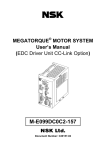
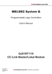
1.1 Replacing with Q series
The Q series does not have a MELSECNET/MINI-S3 master module. For this reason, it is
recommended to use the CC-Link system when replacing the MELSECNET/MINI-S3 system with the Q
series.
(Before replacement)
A/QnA series CPU module
MELSECNET/MINI-S3 master module
MELSECNET/MINI-S3
(After replacement)
Q series CPU module
CC-Link master module
CC-Link
1-1
1 INTRODUCTION
1.2 Suggestions for Replacement with the Remote I/O Module of CCLink System
Module before
replacement
(current status)
MELSECNET/MINI-S3compatible module
(AJ35 - )
Module after replacement
Type
Outline
CC-Link system
compact type remote
I/O module
• Reconfiguration of the system is easy.
Selecting the best match model from the wide
selection of modules for a module before replacement
is possible.
CC-Link system remote
I/O module
(A2C shape)
• Module mounting size is the same.
This A2C shape CC-Link I/O module has the same
shape (same mounting dimensions) with A2C (I/O)
module. No processing for mounting holes is required
when replacing the module.
• I/O signal wiring is the same.
Since the terminal block of the same shape is used,
I/O signal wiring is the same.*1
• Optional products are available.
The A6DIN1C and A2CCOM-TB (sold separately) are
available. If the A2C (I/O) is used before replacement,
it can be utilized.
A2C (I/O) module
(A C)
CC-Link system remote
I/O module
• Change in wiring is unnecessary.
By using a wiring conversion adapter, terminal block of
the module before replacement can be utilized to the
module after replacement *2 (regarding communication
cable and power cable, wiring change is required).
Corresponding module
(before replacement
after
replacement)
(All models)
AX41C/AX81C
AJ65DBTB1-32D
AY51C
AJ65DBTB1-32T1
AX40Y50C
AJ65DBTB1-32DT1
AY13C
AJ65DBTB1-32R
AX40Y10C
AJ65DBTB1-32DR
AJ35TB1-16D
AJ65BTB1-16D
AJ35TB2-16D
AJ65BTB2-16D
AJ35TB1-16T
AJ65BTB1-16T
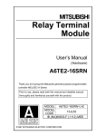
*1 Man-hour taken for wiring change can be reduced since wiring to the external device can also be used by partially
changing the wiring of power cable and communication cable.
After replacing the module,
mount the wiring terminal block.
Remove the wiring
terminal block from
existing I/O module.
Wiring of communication cable and
power cable needs to be changed.
*2 Image figure of replacement using wiring conversion adapter
CC-Link remote I/O module
MINI-S3 module
A6ADP
MINI-S3
terminal block
MINI-S3
terminal block
1-2
1 INTRODUCTION
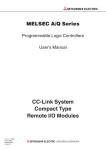
1.3 Suggestions for Replacement with Renewal tool for A0J2
1.3.1 Advantages of using renewal tool for A0J2 (manufactured by Mitsubishi Electric
System & Service Co., Ltd.)
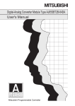
(1) The MELSECNET/MINI-S3 system can be replaced with CC-Link without changing
existing wiring.
Although the CPU module, A/QnA series is replaced with the Q series, the external wiring terminal block
attached to the existing MELSECNET/MINI-S3 I/O module*1 can be utilized to the interface module. It
allows to replace the modules without external wiring change. (The module is replaced with FCN
connector type DC input/output module of CC-Link.)
Also, new wiring is unnecessary since the CC-Link I/O module is connected to the interface module with
dedicated cable.
*1: The MELSECNET/MINI-S3 compact type remote I/O module is the target module.
(Before replacement)
A/QnA series CPU module
MELSECNET/MINI-S3 master module
MELSECNET/MINI-S3
(After replacement)
Q series CPU module
CC-Link master module
Building-up
type
CC-Link
Horizontal
type
Separate
type
1-3
1 INTRODUCTION
POINT
For specifications comparison and functional comparison between the existing MELSECNET/MINI-S3
compact type remote I/O module and the renewal tool for A0J2 after replacement, refer to
APPENDICES.
(2) Processing the mounting holes is unnecessary.
Mounting dimensions of the base adapter included with renewal tool for A0J2 is the same with
dimensions of existing A0J2 I/O module. Replacement without processing the mounting holes is
possible.
(3) I/O address change is unnecessary.
By replacing the MELSECNET/MINI-S3 compact type remote I/O module with FCN connector type DC
input/output module of CC-Link, the I/O address assignment of the MELSECNET/MINI-S3 compact type
remote I/O module can be utilized.
It eliminates I/O address change and allows substantial reduction of program correction.
POINT
1) Renewal tool for A0J2
This tool is used for the following replacement.
• Replacing the A0J2 (H) system with Q series
• Replacing the A0J2 (H) system with AnS series
• Replacing the MELSECNET/MINI-S3 compact type remote I/O module with FCN connector
type DC input/output module of CC-Link
It is composed of interface module to which wiring terminal block of existing I/O module can be
attached and base adapter for utilizing the existing mounting hole, etc.
Installation method can be selected according to the installation space.
2) Interface module
This module has the conversion function that converts DC output into relay output or AC input into
DC input. Therefore, it can be replaced in combination with FCN connector type DC input/output
module of CC-Link.
Wire between the interface module and the CC-Link I/O module with dedicated connection cable.
(List of models supporting interface module)
Discontinued modules (MELSECNET/MINI(-S3))
Product name
Output module
I/O module
Model name
Alternative modules (CC-Link)
Alternative programmable controller I/O module
Interface module
AJ35PTF-24R
AJ65SBTCF1-32T
SC-A0JQIF24R
AJ35PTF-28DR
AJ65SBTCF1-32D, AJ65SBTCF1-32T
SC-A0JQIF28DR
AJ35PTF-28DT
AJ65SBTCF1-32D, AJ65SBTCF1-32T
SC-A0JQIF28DT
AJ35PTF-56AR
AJ65SBTCF1-32D, AJ65SBTCF1-32T
SC-A0JQIF56AR
AJ35PTF-56DR
AJ65SBTCF1-32D, AJ65SBTCF1-32T
SC-A0JQIF56DR
AJ35PTF-56DT
AJ65SBTCF1-32D, AJ65SBTCF1-32T
SC-A0JQIF56DT
1-4
1 INTRODUCTION
1.3.2 Proposal of replacement with renewal tool for A0J2
(1) Building-up type
The CC-Link I/O module can be built up to the existing panel if there is room for depth in front of
existing module, and can be installed on the installation surface of the existing panel.
(After replacement)*1
(Before replacement)
*1: Up to two interface modules can be used for each renewal tool for A0J2.
(2) Horizontal type
The CC-Link I/O module can be installed horizontally, if there is room above the existing module.
(Before replacement)
(After replacement)
*1
*1: Up to two interface modules can be used for each renewal tool for A0J2.
(3) Separate type
Only the CC-Link I/O module can be installed separately (Only this method is available for the AnS
series).
(Before replacement)
(After replacement)
Remark
Other than CC-Link, replacement to the QCPU or AnSCPU is possible.
For details, contact your local Mitsubishi sales representative. (refer to Section 1.5).
1-5
1 INTRODUCTION
1.4 Precautions for Replacement
(a) Before replacing MELSECNET/MINI-S3 with CC-Link, be sure to refer to the manuals for
each of the CC-Link modules, and confirm the functions, specifications and methods of
use of the modules.
(b) For replacement using renewal tool for A0J2, always refer to the following manual.
Select correct products after checking the functions, specifications, and usage.
(Reference manual)
• Renewal tool for A0J2 series transition from MELSEC-A0J2(H) series to renewal system using
renewal tool (Refer to Appendix 2.5.)
(c) When stations installing a MELSECNET/MINI-S3 - CC-Link module wiring conversion
adapter to the CC-Link remote I/O module (AJ65BTB1-16D, AJ65BTB2-16D or AJ65BTB116T) is mixed, the maximum number of connected modules is 32 with the use of a
version 1.10 compatible CC-Link dedicated cable.
(No restrictions when using cables other than a version 1.10 compatible CC-Link
dedicated cable.)
(d) After replacing MELSECNET/MINI-S3 with CC-Link, be sure to check operation of the
entire system before starting actual operation.
1.5 Contact of the Relevant Products
Renewal tool manufactured by Mitsubishi Electric Engineering Co., Ltd.
For products manufactured by Mitsubishi Electric Engineering Co., Ltd., contact your local sales
representative.
Introduction of "replacement of MELSEC-A series, system renewal service, and renewal tool for
A0J2"
For replacement of MELSEC-A series and system renewal service, contact your local sales
representative.
1-6
2 PERFORMANCE SPECIFICATIONS COMPARISONS
2
PERFORMANCE SPECIFICATIONS
COMPARISONS
2
2.1 Performance Specifications Comparisons between
MELSECNET/MINI-S3 and CC-Link
: Compatible,
Item
Specifications
MELSECNET/MINI-S3
CC-Link
64 stations (8 points/station)
64 stations (32 points/station)
1024 points *1
4096 points + 512 words
: Partial change required,
: Not compatible
CompatiPrecautions for replacement
bility
Per master station
Max.
number of
link
stations
Maximum
control I/O
points
When setting parameters with GX
Number of master
modules mounted
Max. 64 modules
(according to the specifications for the
CPU module used.)
Developer: 8 modules *2*3*4
When setting parameters with dedicated
instructions: Max. 64 modules
(according to the specifications for the
CPU module used.)
Communication
speed
Transmission
method
1.5Mbps
156k/625k/2.5M/5M/10Mbps
Ring
Bus
New cable must be laid.
When the transmission
Overall cable
distance
No restriction
1200m (at 156kbps)
distance exceeds 1200m,
use a CC-Link repeater
module.
Max. transmission
distance between
stations
Number of
occupied I/O points
per stations
2-1
Optical data link: 50m
(35m)*5
Twisted pair data link: 100m (50m)*6
In I/O dedicated mode: 32 points
In extended mode: 48 points
1200m (at 156kbps)
32 points
2 PERFORMANCE SPECIFICATIONS COMPARISONS
*1: When 16 separate refresh type remote I/O modules AJ35PTF-128DT (number of occupied stations: 4) are connected,
1024 I/O points each can be controlled.
*2: The following CPU modules have the restriction of the number of modules mounted.
• Q00J/Q00/Q01CPU: 2
• Q00UJ/Q00U/Q01UCPU: 2
• Q02UCPU: 4
*3: When more than 4 modules are used by the parameter setting in GX Developer, refer to the following to check the version for
the CPU module and GX Developer.
• MELSEC-Q CC-Link System Master/Local Module User's Manual
*4: Total number of CC-Link master stations and local stations.
*5: When a 2VTPE-1 optical combined vinyl-insulated sheath cable (manufactured by Mitsubishi Cable Industries, Ltd.) is used,
the max. transmission distance between stations is 35m.
*6: The max. transmission distance between stations varies according to the size of the twisted pair cable.
0.2mm2 or more to less than 0.5mm2 ... 50m,
0.5mm2 or more ... 100m
2-2
2 PERFORMANCE SPECIFICATIONS COMPARISONS
2.2 Wiring in CC-Link
New cables must be laid when replacing MELSECNET/MINI-S3 with CC-Link as the two systems differ
in the applicable cable types.
2.2.1 CC-Link Ver.1.00 cable specifications
(1) Connection method
Master module
(Blue)
DA
Terminating
(White)
resistor
DB
(Yellow)
DG
SLD
FG
CC-Link
compatible cable
Remote module
(Blue)
(Blue)
DA
(White)
(White)
DB
(Yellow)
(Yellow)
DG
SLD
FG
Local module
(Blue)
DA
Terminating
(White)
resistor
DB
(Yellow)
DG
CC-Link
compatible cable
SLD
FG
In the CC-Link system, the terminal resistor to be connected varies according to the cable to be used.
Cable type
2-3
Terminal resistor
CC-Link dedicated cable
110
1/2 W (brown/brown/brown)
CC-Link dedicated high-performance cable
130
1/2 W (brown/orange/brown)
2 PERFORMANCE SPECIFICATIONS COMPARISONS
(2) Cable length between stations, max. overall cable length
1) When the system is composed of only remote I/O stations and remote device stations
Remote I/O station
or
remote device station
Remote I/O station
or
remote device station
Master station
*2
*2
Remote I/O station
or
remote device station
*1
Remote I/O station
or
remote device station
*1
Max. overall cable length
*1: Cable length between remote I/O stations or remote device stations
*2: Cable length between master station and next stations
CC-Link dedicated cable (110
used as terminal resistor)
Cable length between stations
Transmission speed
*1
Max. overall cable length
*2
156kbps
1200m
625kbps
30cm or more
600m
2.5Mbps
200m
30cm to 59cm*
5Mbps
60cm or more
1m or more
30cm to 59cm*
10Mbps
50m
60cm to 99cm*
80m
1m or more
100m
CC-Link dedicated high-performance cable (130
Transmission speed
110m
150m
used as terminal resistor)
Cable length between stations
*1
*2
Max. overall cable length
156kbps
1200m
625kbps
900m
2.5Mbps
400m
5Mbps
Number of
150m
30cm or more
connected
100m
modules
:1 to 32
Number of
10Mbps
30cm to 39cm*
1m or more
80m
connected
modules
40cm or more
100m
Number of
30cm to 39cm*
20m
connected
40cm to 69cm*
30m
70cm or more
100m
:33 to 48
modules
:49 to 64
*
When an actual cable length between remote I/O stations or remote device stations is in this range at even one location,
the above max. overall cable length applies.
2-4
2 PERFORMANCE SPECIFICATIONS COMPARISONS
2) When the system is composed of remote I/O stations, remote device stations, local stations,
and intelligent device stations
Remote I/O station
or
remote device station
Master station
*2
*1
Local station
or
intelligent
device station
Local station
or
intelligent
device station
Remote I/O station
or
remote device station
*2
*2
Max. overall cable length
*1: Cable length between remote I/O stations or remote device stations
*2: Cable length between master/local stations or intelligent device stations and next stations
CC-Link dedicated cable (110
Transmission speed
used as terminal resistor)
Cable length between stations
*1
Max. overall cable length
*2
156kbps
625kbps
1200m
30cm or more
600m
2.5Mbps
5Mbps
200m
30cm to 59cm*
60cm or more
2m or more
30cm to 59cm*
10Mbps
50m
60cm to 99cm*
80m
1m or more
100m
CC-Link dedicated high-performance cable (130
Transmission speed
used as terminal resistor)
Cable length between stations
*1
*2
156kbps
625kbps
10Mbps
*
600m
200m
30cm to 59cm*
2m or more
110m
60cm or more
150m
70cm to 99cm*
50m
1m or more
80m
When an actual cable length between remote I/O stations or remote device stations is in this range at even one location,
the above max. overall cable length applies.
2-5
Max. overall cable length
1200m
30cm or more
2.5Mbps
5Mbps
110m
150m
2 PERFORMANCE SPECIFICATIONS COMPARISONS
2.2.2 CC-Link Ver.1.10 cable specifications
(1) Connection method
Remote module
(Blue)
(Blue)
DA
(White)
(White)
DB
(Yellow)
(Yellow)
DG
Master module
(Blue)
DA
Terminating
(White)
resistor
DB
(Yellow)
DG
SLD
FG
SLD
CC-Link
compatible cable
Local module
(Blue)
DA
Terminating
(White)
resistor
DB
(Yellow)
DG
SLD
CC-Link
compatible cable
FG
Cable type
FG
Terminal resistor
Ver1.10-compatible CC-Link dedicated cable
110
1/2 W (brown/brown/brown)
(2) Cable length between stations, max. overall cable length
Master station
Remote I/O station
or
remote device station
Remote I/O station
or
remote device station
Local station
or
intelligent
device station
Local station
or
intelligent
device station
Cable length between stations
Max. overall cable length
Ver.1.10-compatible CC-Link dedicated cable (110
Transmission speed
Cable length between stations
156kbps
Max. overall cable length
1200m
625kbps
2.5Mbps
used as terminal resistor)
900m
20cm or more
400m
5Mbps
160m
10Mbps
100m
2-6
3 FUNCTIONAL COMPARISONS
3
FUNCTIONAL COMPARISONS
3
3.1 Functional Comparisons between MELSECNET/MINI-S3 and
CC-Link
: Compatible,
Specifications
Item
MELSECNET/MINI-S3
Communication
with remote
Others
3-1
Communication /
line error detection
Line check
RAS function
station
CC-Link
Communication with batch refresh type
Communication with remote I/O
remote I/O modules, separate refresh
stations, remote device stations, local
type remote I/O modules and remote
stations, and intelligent device stations
terminal modules is possible.
is possible.
Communications with all stations
Only the faulty station is disconnected,
sometimes is discontinued when an
and communication with other stations
error occurs on even one station.
is continued normally.
The faulty station is detected on the
The faulty station is detected on the
master station and is stored to buffer
master station and is stored to buffer
memory.
memory.
Breakage of the optical cables and
twisted pair cables can be checked by
changing the operation mode of the
master station.
Monitor
The I/O status of the remote I/O module
station
can be monitored by the LEDs on the
function
master station.
: Partial change required,
: Not compatible
CompatiPrecautions for replacement
bility
Create new programs as the
two systems are not
compatible in the program.
The method of confirmation
is different. Review the
program.
Breakage of twisted pair cables can be
checked by changing the operation
mode of the master station.
Connect the programming
None
tool and check by the device
monitor.
4 REPLACING MASTER MODULE/REMOTE MODULE
4
REPLACING MASTER MODULE/REMOTE
MODULE
4
4.1 Replacing Master Module
4.1.1 List of alternative master module models
MELSECNET/MINI-S3 models to be
Alternative model for CC-Link
discontinued
Product name
Model name
Model name
AJ71PT32-S3
Master module
AJ71T32-S3
A1SJ71PT32-S3
A1SJ71T32-S3
Remarks (restrictions)
Examine replacement with CC-Link.
QJ61BT11N
For details, refer to the User's Manual for the respective
module.
4-1
4 REPLACING MASTER MODULE/REMOTE MODULE
4.2 Replacing Remote Module
CC-Link does not have a remote module that uses a building block type I/O module. When changing the
remote module, it is recommended to replace with the respective remote modules or a local station
(QCPU+QJ61BT11N) of CC-Link.
4.2.1 List of alternative remote module models
MELSECNET/MINI-S3 models to be
Alternative models for CC-Link
discontinued
Product name
Remote module
*1:
Model name
Model name
AJ72PT35
None
AJ72T35
None
Remarks (restrictions)
It is recommended to replace with the respective remote
module or a local station*1 (QCPU+QJ61BT11N) of CCLink.
A program is required for local station QJ61BT11N as it cannot directly control I/O modules.
CC-Link local station
MELSECNET/MINI-S3 remote station
4-2
I/O module
I/O module
I/O module
I/O module
QJ61BT11N
Qn(H)CPU
Power supply module
I/O module
I/O module
I/O module
I/O module
AJ72PT35
Power supply module
For this reason, the following system changes are required.
5 REPLACING I/O MODULE
5
5
REPLACING I/O MODULE
5.1 List of Aternative I/O Module Models
MELSECNET/MINI-S3, A2C models
to be discontinued
Product name
Model name
Alternative model for CC-Link
Model name
Remarks (restrictions)
1) Change in external wiring: Required
2) Change in number of modules (2 modules necessary)
3) Change in program
Change in number of occupied I/O points: Required
4) Change in specifications
AX11C
AJ65SBTB2N-16A
Change in rated input voltage: Not required
Change in rated input current: Required
Change in ON voltage/ON current: Not required
Change in OFF voltage/OFF current: Required
Change in input resistance: Required
AX21C
None
5) Change in functions: Required (2-wire type for inputs)
No alternative model
1) Change in external wiring: Required
2) Change in number of modules: Not required
3) Change in program
Change in number of occupied I/O points: Not required
4) Change in specifications
Change in rated input voltage: Required (12/24VAC,
12VDC not allowed)
AX31C
AJ65SBTB1-32D
Change in rated input current: Not required
Change in ON voltage/ON current: Required
Input module
Change in OFF voltage/OFF current: Required
Change in input resistance: Required
Change in input response time: Required
(35/30ms
1.5ms)
5) Change in functions: Required (12/24VAC, 12VDC not
allowed)
1) Change in external wiring: Required
2) Change in number of modules: Not required
3) Change in program
Change in number of occupied I/O points: Not required
4) Change in specifications
Change in rated input voltage: Required (12VDC not
AX41C
AJ65SBTB1-32D
allowed)
Change in rated input current: Not required
Change in ON voltage/ON current: Required
Change in OFF voltage/OFF current: Required
Change in input resistance: Not required
Change in input response time: Required
(10ms
1.5ms)
5) Change in functions: Required (12VDC not allowed)
5-1
5 REPLACING I/O MODULE
MELSECNET/MINI-S3, A2C models to be
Alternative models for CC-Link
discontinued
Product name
Model name
Model name
Remarks (restrictions)
1) Change in external wiring: Required (Communication
cable and power cable only)
2) Change in number of modules: Not required
3) Change in program
Change in number of occupied I/O points: Not
required
4) Change in specifications
AX41C
AJ65DBTB1-32D
Change in rated input voltage: Required (12VDC not
allowed)
Change in rated input current: Required
Change in ON voltage/ON current: Required
Change in OFF voltage/OFF current: Required
Change in input resistance: Required
Change in input response time: Not required
5) Change in functions: Required (12VDC not allowed)
1) Change in external wiring: Required
2) Change in number of modules: Not required
3) Change in program
Change in number of occupied I/O points: Not
required
4) Change in specifications
Change in rated input voltage: Required
Input module
AJ65SBTB1-32D
(12VDC not allowed)
Change in rated input current: Not required
Change in ON voltage/ON current: Required
Change in OFF voltage/OFF current: Required
Change in input resistance: Not required
Change in input response time: Required
(10ms
1.5ms)
5) Change in functions: Required (12VDC not allowed)
AX81C
1) Change in external wiring: Required (Communication
cable and power cable only)
2) Change in number of modules: Not required
3) Change in program
Change in number of occupied I/O points: Not
required
4) Change in specifications
AJ65DBTB1-32D
Change in rated input voltage: Required (12VDC not
allowed)
Change in rated input current: Required
Change in ON voltage/ON current: Required
Change in OFF voltage/OFF current: Required
Change in input resistance: Required
Change in input response time: Not required
5) Change in functions: Required (12VDC not allowed)
5-2
5 REPLACING I/O MODULE
MELSECNET/MINI-S3, A2C models to be
Alternative models for CC-Link
discontinued
Product name
Model name
Model name
Remarks (restrictions)
1) Change in external wiring: Required
2) Change in number of modules: Not required
3) Change in program
Change in number of occupied I/O points: Not
required
4) Change in specifications
Change in rated input voltage: Required
AJ35PTF-32D
AJ65SBTB1-32D
(12VDC not allowed)
Change in rated input current: Required
Change in ON voltage/ON current: Required
Change in OFF voltage/OFF current: Required
Change in input resistance: Not required
Change in input response time: Required
(10ms
1.5ms)
5) Change in functions: Required
(12VDC not allowed, no optics)
1) Change in external wiring: Required
2) Change in number of modules: Not required
3) Change in program
Change in number of occupied I/O points: Required
4) Change in specifications
AJ35TB1-16A
AJ65SBTB2N-16A
Change in rated input voltage: Not required
Change in rated input current: Required
Change in ON voltage/ON current: Not required
Change in OFF voltage/OFF current: Required
Change in input resistance: Required
Input module
5) Change in functions: Required (2-wire type for inputs)
1) Change in external wiring: Required
2) Change in number of modules: Not required
3) Change in program
Change in number of occupied I/O points: Required
4) Change in specifications
Change in rated input voltage: Not required
AJ35TB3-8D
AJ65SBTB3-8D
Change in rated input current: Not required
Change in ON voltage/ON current: Not required
Change in OFF voltage/OFF current: Not required
Change in input resistance: Not required
Change in input response time: Required
(10ms
1.5ms)
5) Change in functions: Not required
1) Change in external wiring: Required
2) Change in number of modules: Not required
3) Change in program
Change in number of occupied I/O points: Required
4) Change in specifications
Change in rated input voltage: Not required
AJ35TB1-16D
AJ65SBTB1-16D
Change in rated input current: Not required
Change in ON voltage/ON current: Not required
Change in OFF voltage/OFF current: Not required
Change in input resistance: Not required
Change in input response time: Required
(10ms
1.5ms)
5) Change in functions: Not required
5-3
5 REPLACING I/O MODULE
MELSECNET/MINI-S3, A2C models
Alternative models for CC-Link
to be discontinued
Product name
Model name
Model name
Remarks (restrictions)
1) Change in external wiring: Required
2) Change in number of modules: Not required
3) Change in program
Change in number of occupied I/O points: Required
4) Change in specifications
AJ35TB1-16D
AJ65BTB1-16D
Change in rated input voltage: Not required
Change in rated input current: Not required
Change in ON voltage/ON current: Not required
Change in OFF voltage/OFF current: Not required
Change in input resistance: Not required
Change in input response time: Not required
5) Change in functions: Not required
1) Change in external wiring: Required
2) Change in number of modules: Not required
3) Change in program
Change in number of occupied I/O points: Required
4) Change in specifications
Change in rated input voltage: Not required
AJ65SBTB3-16D
Change in rated input current: Not required
Change in ON voltage/ON current: Not required
Change in OFF voltage/OFF current: Not required
Change in input resistance: Not required
Change in input response time: Required
(10ms
1.5ms)
5) Change in functions: Required
AJ35TB2-16D
(2-wire type
Input module
3-wire type)
1) Change in external wiring: Required
2) Change in number of modules: Not required
3) Change in program
Change in number of occupied I/O points: Required
4) Change in specifications
AJ65BTB2-16D
Change in rated input voltage: Not required
Change in rated input current: Not required
Change in ON voltage/ON current: Not required
Change in OFF voltage/OFF current: Not required
Change in input resistance: Not required
Change in input response time: Not required
5) Change in functions: Not required
1) Change in external wiring: Required
2) Change in number of modules: Not required
3) Change in program
Change in number of occupied I/O points: Not
required
4) Change in specifications
AJ35TC1-32D
AJ65SBTCF1-32D
Change in rated input voltage: Not required
Change in rated input current: Not required
Change in ON voltage/ON current: Required
Change in OFF voltage/OFF current: Not required
Change in input resistance: Not required
Change in input response time: Required
(10ms
1.5ms)
5) Change in functions: Not required
5-4
5 REPLACING I/O MODULE
MELSECNET/MINI-S3, A2C models
Alternative models for CC-Link
to be discontinued
Product name
Model name
Model name
Remarks (restrictions)
1) Change in external wiring: Required
2) Change in number of modules (2 modules necessary)
3) Change in program
Change in number of occupied I/O points: Required
AJ65SBTB2N-16R
4) Change in specifications
Change in rated output voltage: Not required
Change in rated output current: Not required
5) Change in functions: Required
(2-wire type for outputs)
AY13C
1) Change in external wiring: Required (Communication
cable and power cable only)
2) Change in number of modules: Not required
3) Change in program
AJ65DBTB1-32R
Change in number of occupied I/O points: Not
required
4) Change in specifications
Change in rated output voltage: Not required
Change in rated output current: Not required
5) Change in functions: Not required
1) Change in external wiring: Required
2) Change in number of modules (2 modules necessary)
3) Change in program
Change in number of occupied I/O points: Required
AJ65SBTB2N-16R
4) Change in specifications
Change in rated output voltage: Not required
Change in rated output current: Not required
(Note that a connect life is half.)
Output module
5) Change in functions: Required
AY15CEU
(2-wire type for outputs)
1) Change in external wiring: Required
2) Change in number of modules: Not required
3) Change in program
Change in number of occupied I/O points: : Not
AJ65DBTB1-32R
required
4) Change in specifications
Change in rated output voltage: Not required
Change in rated output current: Not required
5) Change in functions: Not required
1) Change in external wiring: Required
2) Change in number of modules (2 modules necessary)
3) Change in program
Change in number of occupied I/O points: Required
AY23C
AJ65SBTB2N-16S
4) Change in specifications
Change in rated output voltage: Not required
Change in rated output current: Required
5) Change in functions: Required
(2-wire type for outputs)
1) Change in external wiring: Required
2) Change in number of modules: Not required
3) Change in program
Change in number of occupied I/O points: Not
AY51C
AJ65SBTB1-32T1
required
4) Change in specifications
Change in rated output voltage: Not required
Change in rated output current: Required
5) Change in functions: Not required
5-5
5 REPLACING I/O MODULE
MELSECNET/MINI-S3, A2C models
Alternative models for CC-Link
to be discontinued
Product name
Model name
Model name
Remarks (restrictions)
1) Change in external wiring: Required (Communication
cable and power cable only)
2) Change in number of modules: Not required
3) Change in program
AY51C
AJ65DBTB1-32T1
Change in number of occupied I/O points: Not
required
4) Change in specifications
Change in rated output voltage: Not required
Change in rated output current: Required
5) Change in functions: Not required
1) Change in external wiring: Required
2) Change in number of modules (2 modules necessary)
3) Change in program
Change in number of occupied I/O points: Required
AJ65SBTB1-16TE
4) Change in specifications
Change in rated output voltage: Required
(5VDC not allowed)
Change in rated output current: Required (2A
0.1A)
5) Change in functions: Required (5VDC not allowed)
AY61CE
1) Change in external wiring: Required
2) Change in number of modules: Not required
3) Change in program
Change in number of occupied I/O points: Not
AJ65SBTB1-32TE1
required
4) Change in specifications
Change in rated output voltage: Required (5VDC not
allowed)
Change in rated output current: Required (2A
Output module
0.5A)
5) Change in functions: Required (5VDC not allowed)
1) Change in external wiring: Required
2) Change in number of modules (2 modules necessary)
3) Change in program
Change in number of occupied I/O points: Required
AJ65SBTB1-16TE
4) Change in specifications
Change in rated output voltage: Required
Change in rated output current: Required
(0.5A
0.1A)
5) Change in functions: Not required
AY81C
1) Change in external wiring: Required
2) Change in number of modules: Not required
3) Change in program
Change in number of occupied I/O points: : Not
AJ65SBTB1-32TE1
required
4) Change in specifications
Change in rated output voltage: Not required
Change in rated output current: Not required
5) Change in functions: Not required
1) Change in external wiring: Required
2) Change in number of modules (2 modules necessary)
3) Change in program
Change in number of occupied I/O points: Required
AJ35PTF-24S
AJ65SBTB2N-16S
4) Change in specifications
Change in rated output voltage: Not required
Change in rated output current: Not required
5) Change in functions: Required
(2-wire type for outputs, no high-speed type fuse , no
optics)
5-6
5 REPLACING I/O MODULE
MELSECNET/MINI-S3, A2C models
Alternative models for CC-Link
to be discontinued
Product name
Model name
Model name
Remarks (restrictions)
1) Change in external wiring: Required
2) Change in number of modules: Not required
3) Change in program
AJ35PTF-24T
AJ65SBTB1-32T1
Change in number of occupied I/O points: Required
4) Change in specifications
Change in rated output voltage: Not required
Change in rated output current: Not required
5) Change in functions: Required (no optics)
1) Change in external wiring: Required
2) Change in number of modules: Not required
3) Change in program
Change in number of occupied I/O points: Required
AJ35TB1A-8R
AJ65SBTB2N-8R
4) Change in specifications
Change in rated output voltage: Not required
Change in rated output current: Not required
5) Change in functions: Required
(Change to 16 points per common (2-wire type))
1) Change in external wiring: Required
2) Change in number of modules: Not required
3) Change in program
AJ35TB2-8R
AJ65SBTB2N-8R
Change in number of occupied I/O points: Required
4) Change in specifications
Change in rated output voltage: Not required
Change in rated output current: Not required
5) Change in functions: Not required
1) Change in external wiring: Required
Output module
2) Change in number of modules: Not required
3) Change in program
Change in number of occupied I/O points: Required
AJ35TB1-16R
AJ65SBTB2N-16R
4) Change in specifications
Change in rated output voltage: Not required
Change in rated output current: Not required
5) Change in functions: Required
(2-wire type for outputs)
1) Change in external wiring: Required
2) Change in number of modules: Not required
3) Change in program
Change in number of occupied I/O points: Required
AJ35TB1A-8T
AJ65SBTB1-8T1
4) Change in specifications
Change in rated output voltage: Required
Change in rated output current: Required
5) Change in functions: Required
(Change to 16 points per common (2-wire type) )
1) Change in external wiring: Required
2) Change in number of modules: Not required
3) Change in program
Change in number of occupied I/O points: Required
AJ35TB2-8T
AJ65SBTB2-8T1
4) Change in specifications
Change in rated input voltage: Required
(5VDC not allowed)
Change in rated output current: Not required
5) Change in functions: Required (5VDC not allowed)
5-7
5 REPLACING I/O MODULE
MELSECNET/MINI-S3, A2C models
Alternative model for CC-Link
to be discontinued
Product name
Model name
Model name
Remarks (restrictions)
1) Change in external wiring: Required
2) Change in number of modules: Not required
3) Change in program
AJ65SBTB1-16T1
Change in number of occupied I/O points: Required
4) Change in specifications
Change in rated output voltage: Required
Change in rated output current: Required
5) Change in functions: Not required
AJ35TB1-16T
1) Change in external wiring: Required
2) Change in number of modules: Not required
3) Change in program
AJ65BTB1-16T
Change in number of occupied I/O points: Required
4) Change in specifications
Change in rated output voltage: Not required
Change in rated output current: Not required
5) Change in functions: Not required
1) Change in external wiring: Required
2) Change in number of modules: Not required
3) Change in program
AJ35TB2-16T
AJ65SBTB2-16T1
Change in number of occupied I/O points: Required
4) Change in specifications
Change in rated output voltage: Required
Output module
Change in rated output current: Required
5) Change in functions: Not required
1) Change in external wiring: Required
2) Change in number of modules: Not required
3) Change in program
Change in number of occupied I/O points: Not
AJ35TC1-32T
AJ65SBTCF1-32T
required
4) Change in specifications
Change in rated output voltage: Required
Change in rated output current: Not required
5) Change in functions: Not required
6) Others: External wiring connectors not attached
1) Change in external wiring: Required
2) Change in number of modules: Required (2 modules
necessary)
3) Change in program
AJ35PTF-24R*1
AJ65SBTB2N-16R
Change in number of occupied I/O points: Required
4) Change in specifications
Change in rated output voltage: Not required
Change in rated output current: Not required
5) Change in functions: Required (2-wire type for
outputs, no optics)
*1: Replacement using renewal tool for A0J2 is possible (refer to Appendix 1).
5-8
5 REPLACING I/O MODULE
MELSECNET/MINI-S3, A2C models
Alternative model for CC-Link
to be discontinued
Product name
Model name
Model name
Remarks (restrictions)
1) Change in external wiring: Required
2) Change in number of modules (2 modules necessary)
3) Change in program
Change in number of occupied I/O points: Required
4) Change in specifications
AJ65SBTB2N-16A
AX10Y10C
+
AJ65SBTB2N-16R
Change in rated input voltage: Not required
Change in rated input current: Required
Change in ON voltage/ON current: Not required
Change in OFF voltage/OFF current: Required
Change in input resistance: Required
Change in rated output voltage: Not required
Change in rated output current: Not required
5) Change in functions: Required (2-wire type for I/Os)
I/O module
1) Change in external wiring: Required
2) Change in number of modules (2 modules necessary)
3) Change in program
Change in number of occupied I/O points: Required
4) Change in specifications
AJ65SBTB2N-16A
AX10Y22C
+
AJ65SBTB2N-16S
Change in rated input voltage: Not required
Change in rated input current: Required
Change in ON voltage/ON current: Not required
Change in OFF voltage/OFF current: Required
Change in input resistance: Required
Change in rated output voltage: Not required
Change in rated output current: Required
5) Change in functions: Required (2-wire type for I/Os)
5-9
5 REPLACING I/O MODULE
MELSECNET/MINI-S3, A2C models
Alternative models for CC-Link
to be discontinued
Product name
Model name
Model name
Remarks (restrictions)
1) Change in external wiring: Required
2) Change in number of modules (2 modules necessary)
3) Change in program
Change in number of occupied I/O points: Required
4) Change in specifications
Change in rated input voltage: Required
(12VDC not allowed)
AJ65SBTB1-16D
+
AJ65SBTB2N-16R
Change in rated input current: Required
Change in ON voltage/ON current: Required
Change in OFF voltage/OFF current: Required
Change in input resistance: Not required
Change in input response time: Required
(10ms
1.5ms)
Change in rated output voltage: Not required
Change in rated output current: Not required
5) Change in functions: Required
AX40Y10C
(2-wire type for outputs, 12VDC not allowed)
1) Change in external wiring: Required
2) Change in number of modules: Required (2 modules
necessary)
3) Change in program
Change in number of occupied I/O points: Required
4) Change in specifications
Change in rated input voltage: Required
I/O module
AJ65SBTB32-16DR
(12VDC not allowed)
Change in rated input current: Required
Change in ON voltage/ON current: Required
Change in OFF voltage/OFF current: Required
Change in input resistance: Not required
Change in rated output voltage: Not required
Change in rated output current: Not required
5) Change in functions: Required (12VDC not allowed)
1) Change in external wiring: Required (Communication
cable and power cable only)
2) Change in number of modules: Not required
3) Change in program
Change in number of occupied I/O points: Not
required
4) Change in specifications
AX40Y10C
AJ65DBTB1-32DR
Change in rated input voltage: Required
(12VDC not allowed)
Change in rated input current: Required
Change in ON voltage/ON current: Required
Change in OFF voltage/OFF current: Required
Change in input resistance: Required
Change in rated output voltage: Not required
Change in rated output current: Not required
5) Change in functions: Required (12VDC not allowed)
5 - 10
5 REPLACING I/O MODULE
MELSECNET/MINI-S3, A2C models
Alternative models for CC-Link
to be discontinued
Product name
Model name
Model name
Remarks (restrictions)
1) Change in external wiring: Required
2) Change in number of modules: Not required
3) Change in program
Change in number of occupied I/O points: Not
required
4) Change in specifications
Change in rated input voltage: Required
(12VDC not allowed)
AJ65SBTB1-32DT2
Change in rated input current: Required
Change in ON voltage/ON current: Required
Change in OFF voltage/OFF current: Required
Change in input resistance: Not required
Change in input response time: Required
(10ms
1.5ms)
Change in rated output voltage: Required
(12VDC not allowed)
Change in rated output current: Required
I/O module
AX40Y50C
5) Change in functions: Required (12VDC not allowed)
1) Change in external wiring: Required (Communication
cable and power cable only)
2) Change in number of modules: Not required
3) Change in program
Change in number of occupied I/O points: Not
required
4) Change in specifications
Change in rated input voltage: Required
AJ65DBTB1-32DT1
(12VDC not allowed)
Change in rated input current: Required
Change in ON voltage/ON current: Required
Change in OFF voltage/OFF current: Required
Change in input resistance: Required
Change in input response time: Not required
Change in rated output voltage: Not required
Change in rated output current: Required
5) Change in functions: Required (12VDC not allowed)
5 - 11
5 REPLACING I/O MODULE
MELSECNET/MINI-S3, A2C models
Alternative models for CC-Link
to be discontinued
Product name
Model name
Model name
Remarks (restrictions)
1) Change in external wiring: Required
2) Change in number of modules (2 modules necessary)
3) Change in program
Change in number of occupied I/O points: Required
4) Change in specifications
Change in rated input voltage: Required
(12VDC not allowed)
AJ65SBTB1-16D
+
AJ65SBTB2N-16R
Change in rated input current: Required
Change in ON voltage/ON current: Required
Change in OFF voltage/OFF current: Required
Change in input resistance: Not required
Change in input response time: Required
(10ms
1.5ms)
Change in rated output voltage: Not required
Change in rated output current: Not required
5) Change in functions: Required
AX80Y10C
(2-wire type for outputs, 12VDC not allowed)
1) Change in external wiring: Required (Communication
cable and power cable only)
2) Change in number of modules: Not required
3) Change in program
Change in number of occupied I/O points: Not
required
4) Change in specifications
I/O module
AJ65DBTB1-32DR
Change in rated input voltage: Required
(12VDC not allowed)
Change in rated input current: Required
Change in ON voltage/ON current: Required
Change in OFF voltage/OFF current: Required
Change in input resistance: Required
Change in rated output voltage: Not required
Change in rated output current: Not required
5) Change in functions: Required (12VDC not allowed)
1) Change in external wiring: Required
2) Change in number of modules (2 modules necessary)
3) Change in program
Change in number of occupied I/O points: Required
4) Change in specifications
Change in rated input voltage: Required
AJ65SBTB1-16D
AX80Y14CEU
+
AJ65SBTB2N-16R
(12VDC not allowed)
Change in rated input current: Required
Change in ON voltage/ON current: Required
Change in OFF voltage/OFF current: Required
Change in input resistance: Not required
Change in rated output voltage: Not required
Change in rated output current: Not required
(Note that a connect life is half.)
5) Change in functions: Required
(2-wire type for outputs, 12VDC not allowed)
5 - 12
5 REPLACING I/O MODULE
MELSECNET/MINI-S3, A2C models
Alternative models for CC-Link
to be discontinued
Product name
Model name
Model name
Remarks (restrictions)
1) Change in external wiring: Required
2) Change in number of modules (2 modules necessary)
3) Change in program
Change in number of occupied I/O points: Required
4) Change in specifications
Change in rated input voltage: Required
(12VDC not allowed)
AJ65SBTB1-16D
AX80Y80C
+
AJ65SBTB1-16TE
Change in rated input current: Required
Change in ON voltage/ON current: Required
Change in OFF voltage/OFF current: Required
Change in input resistance: Not required
Change in input response time: Required
(10ms
1.5ms)
Change in rated output voltage: Required
Change in rated output current: Required
(0.5A
0.1A)
5) Change in functions: Required (12VDC not allowed)
1) Change in external wiring: Required
2) Change in number of modules: Not required
3) Change in program
Change in number of occupied I/O points: Not
required
4) Change in specifications
Change in rated input voltage: Required
(12VDC not allowed)
I/O module
AX80Y80C
AJ65SBTB1-32DTE1
Change in rated input current: Required
Change in ON voltage/ON current: Required
Change in OFF voltage/OFF current: Required
Change in input resistance: Not required
Change in input response time: Required
(10ms
1.5ms)
Change in rated output voltage: Not required
Change in rated output current: Not required
5) Change in functions: Required (12VDC not allowed)
1) Change in external wiring: Required
2) Change in number of modules: Required
(4 modules necessary: AJ65SBTB2N-16A
2 modules
AJ65SBTB2N-16R
2 modules)
3) Change in program
Change in number of occupied I/O points: Required
4) Change in specifications
AJ65SBTB2N-16A
AJ35PTF-56AR*1
+
AJ65SBTB2N-16R
Change in rated input voltage: Not required
Change in rated input current: Required
Change in ON voltage/ON current: Required
Change in OFF voltage/OFF current: Required
Change in input resistance: Required
Change in rated output voltage: Not required
Change in rated output current: Not required
(Note that a connect life is half.)
5) Change in functions: Required
(2-wire type for I/Os, no optics)
*1: Replacement using renewal tool for A0J2 is possible (refer to Appendix 1).
5 - 13
5 REPLACING I/O MODULE
MELSECNET/MINI-S3, A2C models
Alternative models for CC-Link
to be discontinued
Product name
Model name
Model name
Remarks (restrictions)
1) Change in external wiring: Required
2) Change in number of modules: Required
(4 modules necessary: AJ65SBTB2N-16A
AJ65SBTB2N-16S
2 modules
2 modules)
3) Change in program
Change in number of occupied I/O points: Required
AJ65SBTB2N-16A
AJ35PTF-56AS
+
AJ65SBTB2N-16S
4) Change in specifications
Change in rated input voltage: Not required
Change in rated input current: Required
Change in ON voltage/ON current: Required
Change in OFF voltage/OFF current: Required
Change in input resistance: Required
Change in rated output voltage: Not required
Change in rated output current: Not required
5) Change in functions: Required (2-wire type for I/Os,
no high-speed fuse, no optics)
1) Change in external wiring: Required
2) Change in number of modules (2 modules necessary)
3) Change in program
Change in number of occupied I/O points: Required
4) Change in specifications
Change in rated input voltage: Required
(12VDC not allowed)
AJ65SBTB1-16D
AJ35PTF-28DS
+
AJ65SBTB2N-16S
I/O module
Change in rated input current: Required
Change in ON voltage/ON current: Required
Change in OFF voltage/OFF current: Required
Change in input resistance: Not required
Change in input response time: Required
(10ms
1.5ms)
Change in rated output voltage: Not required
Change in rated output current: Not required
5) Change in functions: Required (2-wire type for
outputs, no optics, 12VDC not allowed)
1) Change in external wiring: Required
2) Change in number of modules: Required
(3 modules necessary: AJ65SBTB1-32D
AJ65SBTB2N-16S
1 module
2 modules)
3) Change in program
Change in number of occupied I/O points: Required
4) Change in specifications
Change in rated input voltage: Required
AJ65SBTB1-32D
AJ35PTF-56DS
+
AJ65SBTB2N-16S
(12VDC not allowed)
Change in rated input current: Required
Change in ON voltage/ON current: Required
Change in OFF voltage/OFF current: Required
Change in input resistance: Not required
Change in input response time: Required
(10ms
1.5ms)
Change in rated output voltage: Not required
Change in rated output current: Not required
5) Change in functions: Required (2-wire type for
outputs, no optics, 12VDC not allowed)
5 - 14
5 REPLACING I/O MODULE
MELSECNET/MINI-S3, A2C models
Alternative models for CC-Link
to be discontinued
Product name
Model name
Model name
Remarks (restrictions)
1) Change in external wiring: Required
2) Change in number of modules: Required
(2 modules necessary: AJ65SBTB1-32D
AJ65SBTB2N-16R
1 module
1 modules)
3) Change in program
Change in number of occupied I/O points: Required
4) Change in specifications
Change in rated input voltage: Required
AJ65SBTB1-32D
AJ35PTF-28DR*1
+
AJ65SBTB2N-16R
(12VDC not allowed)
Change in rated input current: Required
Change in ON voltage/ON current: Required
Change in OFF voltage/OFF current: Required
Change in input resistance: Not required
Change in input response time: Required
(10ms
1.5ms)
Change in rated output voltage: Required
Change in rated output current: Required
5) Change in functions: Required (2-wire type for
outputs, no optics, 12VDC not allowed)
1) Change in external wiring: Required
I/O module
2) Change in number of modules: Required
(3 modules necessary: AJ65SBTB1-32D
AJ65SBTB2N-16R
1 module
2 modules)
3) Change in program
Change in number of occupied I/O points: Required
4) Change in specifications
Change in rated input voltage: Required
AJ65SBTB1-32D
AJ35PTF-56DR*1
+
AJ65SBTB2N-16R
(12VDC not allowed)
Change in rated input current: Required
Change in ON voltage/ON current: Required
Change in OFF voltage/OFF current: Required
Change in input resistance: Not required
Change in input response time: Required
(10ms
1.5ms)
Change in rated output voltage: Not required
Change in rated output current: Not required
5) Change in functions: Required (2-wire type for
outputs, no optics, 12VDC not allowed)
*1: Replacement using renewal tool for A0J2 is possible (refer to Appendix 1).
5 - 15
5 REPLACING I/O MODULE
MELSECNET/MINI-S3, A2C models
Alternative models for CC-Link
to be discontinued
Product name
Model name
Model name
Remarks (restrictions)
1) Change in external wiring: Required
2) Change in number of modules (2 modules necessary)
3) Change in program
Change in number of occupied I/O points: Not
required
4) Change in specifications
Change in rated input voltage: Required
AJ65SBTB1-32D
AJ35PTF-28DT*1
+
AJ65SBTB1-32T1
(12VDC not allowed)
Change in rated input current: Required
Change in ON voltage/ON current: Required
Change in OFF voltage/OFF current: Required
Change in input resistance: Not required
Change in input response time: Required
(10ms
1.5ms)
Change in rated output voltage: Not required
Change in rated output current: Not required
5) Change in functions: Required (no optics, 12VDC not
allowed)
1) Change in external wiring: Required
2) Change in number of modules (2 modules necessary)
3) Change in program
Change in number of occupied I/O points: Not
required
4) Change in specifications
I/O module
Change in rated input voltage: Required
AJ65SBTB1-32D
AJ35PTF-56DT*1
+
AJ65SBTB1-32T1
(12VDC not allowed)
Change in rated input current: Required
Change in ON voltage/ON current: Required
Change in OFF voltage/OFF current: Required
Change in input resistance: Not required
Change in input response time: Required
(10ms
1.5ms)
Change in rated output voltage: Not required
Change in rated output current: Not required
5) Change in functions: Required (no optics, 12VDC not
allowed)
1) Change in external wiring: Required
2) Change in number of modules (2 modules necessary)
3) Change in program
Change in number of occupied I/O points: Required
4) Change in specifications
AJ65SBTB2N-8A
AJ35TB1-16AR
+
AJ65SBTB2N-8R
Change in rated input voltage: Not required
Change in rated input current: Required
Change in ON voltage/ON current: Not required
Change in OFF voltage/OFF current: Required
Change in input resistance: Required
Change in rated output voltage: Not required
Change in rated output current: Not required
5) Change in functions: Required (2-wire type for I/Os)
*1: Replacement using renewal tool for A0J2 is possible (refer to Appendix 1).
5 - 16
5 REPLACING I/O MODULE
MELSECNET/MINI-S3, A2C models
Alternative models for CC-Link
to be discontinued
Product name
Model name
Model name
Remarks (restrictions)
1) Change in external wiring: Required
2) Change in number of modules (2 modules necessary)
3) Change in program
Change in number of occupied I/O points: Required
4) Change in specifications
Change in rated input voltage: Not required
AJ65SBTB1-8D
AJ35TB1-16DR
+
AJ65SBTB2N-8R
Change in rated input current: Not required
Change in ON voltage/ON current: Not required
Change in OFF voltage/OFF current: Not required
Change in input resistance: Not required
Change in input response time: Required
(10ms
1.5ms)
Change in rated output voltage: Not required
Change in rated output current: Not required
5) Change in functions: Required
(2-wire type for outputs)
1) Change in external wiring: Required
2) Change in number of modules: Not required
3) Change in program
Change in number of occupied I/O points: Required
4) Change in specifications
Change in rated input voltage: Not required
Change in rated input current: Not required
I/O module
AJ35TB1-16DT
AJ65SBTB1-16DT2
Change in ON voltage/ON current: Not required
Change in OFF voltage/OFF current: Not required
Change in input resistance: Not required
Change in input response time: Required
(10ms
1.5ms)
Change in rated output voltage: Not required
Change in rated output current: Required
5) Change in functions: Not required
1) Change in external wiring: Required
2) Change in number of modules: Not required
3) Change in program
Change in number of occupied I/O points: Not
required
4) Change in specifications
Change in rated input voltage: Not required
Change in rated input current: Not required
AJ35TC1-32DT
AJ65SBTCF1-32DT
Change in ON voltage/ON current: Not required
Change in OFF voltage/OFF current: Not required
Change in input resistance: Not required
Change in input response time: Required
(10ms
1.5ms)
Change in rated output voltage: Required
Change in rated output current: Not required
5) Change in functions: Not required
6) Others: External wiring connectors not attached
5 - 17
5 REPLACING I/O MODULE
5.2 I/O Module Specifications Comparison
5.2.1 Input module specifications comparison
(1) Specifications comparison between AX11C and AJ65SBTB2N-16A
: Compatible,
Specifications
AX11C
AJ65SBTB2N-16A
: Partial change required,
: Not compatible
Precautions for
Compatibility
replacement
When seventeen or more
Number of input points
points are used, use two
32 points
16 points
Photocoupler
Photocoupler
AJ65SBTB2N-16A
modules.
Insulation method
Rated input voltage
100-120VAC, 50/60Hz
100-120VAC, 50/60Hz
Rated input current
Approx. 6mA (100VAC, 60Hz)
Approx. 7mA (100VAC, 60Hz)
Operating voltage range
85 to 132VAC
85 to 132VAC
(50/60Hz
5%)
(50/60Hz
3%,
distortion rate 5% within)
100% simultaneously ON
Maximum number of
75% simultaneously ON
(at 110VAC)
(at 110VAC)
60% simultaneously ON
Max. 200mA, within 1ms
Max. 200mA, within 1ms
simultaneous input points
(at 132VAC)
Inrush current
ON voltage/ON current
OFF voltage/OFF current
Input impedance
(with 132VAC)
(with 132VAC)
80V or more/5mA or more
80V or more/5mA or more
30V or less/1mA or less
30V or less/1.7mA or less
Approx. 18k
(60Hz),
Approx. 15k
(60Hz),
Approx. 21k
(50Hz)
Approx. 18k
(50Hz)
Response
OFF
ON
15ms or less (100VAC, 60Hz)
20ms or less (100VAC, 60Hz)
time
ON
OFF
30ms or less (100VAC, 60Hz)
20ms or less (100VAC, 60Hz)
Common terminal
arrangement
16 points/common
Number of occupied
stations (number of
occupied points)
Operation indication
16 points/common
(2-wire type)
4 stations
(4 stations
8 points)
ON indication (LED)
The number of points
1 station
(1 station
32 points)
assigned per module is not
changed.
ON indication (LED)
Transmission/module power
50-point terminal block
External connection
method
(M3.5
7 screws)
Transmission circuit part
included
supply parts:
7-point terminal block
(M3
(M3
Applicable solderless
terminal
R1.25-3.5, R2-3.5
RAV1.25-3.5, RAV2-3.5
Voltage
15.6 to 31.2VDC
I/O
supply
5.2 screws)
0.3 to 2mm2
RAV1.25-3
(Conforming to JIS C 2805)
Change in wiring is required.
V2-MS3 , RAP2-3SL, TGV2-3N
20.4 to 26.4VDC
(ripple ratio within 5%)
The operating voltage range
differs.
The current consumption
module
power
Change in wiring is required.
34-point terminal block
0.75 to 2mm2
Applicable wire size
5.2 screws)
I/O part:
40mA or less
Current
56mA (at 24V TYP.)
(24VDC when all points
are ON)
increases by using two
AJ65SBTB2N-16As. The
current capacity needs to be
reconsidered.
The overall size differs.
External dimensions
170(H)
64(W)
80(D) mm
54(H)
179(W)
40(D)mm
Pay attention to the
mounting dimensions.
Weight
5 - 18
0.62kg
0.25kg
5 REPLACING I/O MODULE
(2) Specifications comparison between AX31C and AJ65SBTB1-32D
: Compatible,
Specifications
AX31C
Number of input points
Insulation method
Rated input voltage
AJ65SBTB1-32D
32 points
32 points
Photocoupler
Photocoupler
12/24VAC
12/24VDC
: Partial change required,
: Not compatible
Precautions for
Compatibility
replacement
12/24VAC, 12VDC cannot
24VDC
50/60Hz
be used.*1
12/24VAC, 12VDC cannot
4mA (12VAC/DC),
Rated input current
Approx. 7mA
8.5mA (24VAC/DC)
be used.*1
Rated input current is
smaller.*2
10.2 to
Operating voltage range
26.4VDC
10.2 to 26.4VAC
(ripple ratio
(50/60Hz
5%)
19.2 to 26.4VDC
(ripple ratio within 5%)
12/24VAC, 12VDC cannot
be used.*1
within 5%)
Maximum number of
70% simultaneously ON
simultaneous input points
ON voltage/ON current
(at 26.4VAC)
7V or more/2mA or more
2.5V or more
OFF voltage/OFF current
Input resistance (Input
impedance)
OFF
ON
Response
time
ON
OFF
0.7mA or less
100% simultaneously ON
14V or more/3.5mA or more
6V or less/1.7mA or less
Approx 2.7k
Approx. 3.3k
12/24VAC, 12VDC cannot
be used.*1
12/24VAC, 12VDC cannot
be used.*1
Input resistance is
inreased.*2
35ms or less
30ms or less
(12/24VAC,
(12/24VDC)
1.5ms or less (at 24VDC)
60Hz)
The response times differ.
35ms or less
30ms or less
(12/24VAC,
(12/24VDC)
1.5ms or less (at 24VDC)
60Hz)
As common terminal
arrangement changes from
Common terminal
arrangement
16 points/common
32 points/common
16 points/common to 32
points/common, wiring with
a different voltage per
common is not possible.
Number of occupied
stations (number of
occupied points)
Operation indication
4 stations
(4 stations
8 points)
ON indication (LED)
1 station
(1 station
32 points)
The number of points
assigned per module is not
changed.
ON indication (LED)
Transmission/module power
50-point terminal block
External connection
method
(M3.5
7 screws)
Transmission circuit part
included
supply parts:
7-point terminal block
(M3
5.2 screws)
34-point terminal block
(M3
0.75 to 2mm2
Applicable wire size
Applicable solderless
terminal
I/O
R1.25-3.5, R2-3.5
RAV1.25-3.5, RAV2-3.5
Voltage
15.6 to 31.2VDC
module
power
supply
Change in wiring is required.
I/O part:
5.2 screws)
0.3 to 2mm2
RAV1.25-3
(Conforming to JIS C 2805)
Change in wiring is required.
V2-MS3 , RAP2-3SL ,TGV2-3N
20.4 to 26.4VDC
(ripple ratio within 5%)
The operating voltage range
differs.
45mA or less
Current
56mA (at 24VDC TYP.)
(24VDC when all points
are ON)
The overall size differs.
External dimensions
170(H)
64(W)
80(D) mm
54(H)
179(W)
40(D) mm
Pay attention to the mounting
dimensions.
Weight
0.62kg
0.25kg
*1: To use at 24VAC, convert to direct current externally before inputting.
*2: Confirm the specifications of the sensors or switches to be connected to the AJ65SBTB1-32D.
5 - 19
5 REPLACING I/O MODULE
(3) Specifications comparison between AX41C and AJ65SBTB1-32D
: Compatible,
Specifications
AX41C
Number of input points
Insulation method
AJ65SBTB1-32D
32 points
32 points
Photocoupler
Photocoupler
: Partial change required,
: Not compatible
Precautions for
Compatibility
replacement
Rated input voltage
12VDC/24VDC
24VDC
12VDC cannot be used.
Rated input current
Approx. 3mA/Approx. 7mA
Approx. 7mA
12VDC cannot be used.
10.2 to 31.2VDC
19.2 to 26.4VDC
(ripple ratio within 5%)
(ripple ratio within 5%)
Operating voltage range
Maximum number of
100% simultaneously ON (at
simultaneous input points
ON voltage/ON current
OFF voltage/OFF current
Input resistance
26.4VDC)
100% simultaneously ON
8V or more/2mA or more
14V or more/3.5mA or more
12VDC cannot be used.
4V or less/1mA or less
6V or less/1.7mA or less
12VDC cannot be used.
Approx. 3.3k
Positive common
Input method
12VDC cannot be used.
(sink type)
Approx. 3.3k
Positive/negative common
shared type
(sink/source shared type)
Response
OFF
ON
10ms or less (at 24VDC)
1.5ms or less (at 24VDC)
time
ON
OFF
10ms or less (at 24VDC)
1.5ms or less (at 24VDC)
As common terminal
arrangement changes from
Common terminal
arrangement
16 points/common
32 points/common
16 points/common to 32
points/common, wiring with
a different voltage per
common is not possible.
Number of occupied
stations (number of
occupied points)
Operation indication
4 stations
(4 stations
8 points)
ON indication (LED)
1 station
(1 station
32 points)
The number of points
assigned per module is not
changed.
ON indication (LED)
Transmission/module power
50-point terminal block
External connection
method
(M3.5
7 screws)
Transmission circuit part
included
supply parts:
7-point terminal block
(M3
(M3
Applicable solderless
terminal
I/O
R1.25-3.5, R2-3.5
RAV1.25-3.5, RAV2-3.5
Voltage
15.6 to 31.2VDC
module
power
supply
Change in wiring is required.
34-point terminal block
0.75 to 2mm2
Applicable wire size
5.2 screws)
I/O part:
5.2 screws)
0.3 to 2mm2
RAV1.25-3
(Conforming to JIS C 2805)
Change in wiring is required.
V2-MS3 , RAP2-3SL, TGV2-3N
20.4 to 26.4VDC
(ripple ratio within 5%)
The operating voltage range
differs.
45mA or less
Current
55mA (at 24VDC TYP.)
(24VDC when all points
are ON)
The overall size differs.
External dimensions
170(H)
64(W)
80(D) mm
54(H)
179(W)
40(D) mm
Pay attention to the mounting
dimensions.
Weight
5 - 20
0.6kg
0.25kg
5 REPLACING I/O MODULE
(4) Specifications comparison between AX41C and AJ65DBTB1-32D
: Compatible,
Specifications
AX41C
Number of input points
Insulation method
AJ65DBTB1-32D
32 points
32 points
Photocoupler
Photocoupler
: Partial change required,
: Not compatible
Precautions for
Compatibility
replacement
Rated input voltage
12VDC/24VDC
24VDC
12VDC cannot be used.
Rated input current
Approx. 3mA/Approx. 7mA
Approx. 5mA
12VDC cannot be used.
10.2 to 31.2VDC
20.4 to 31.2VDC
(ripple ratio within 5%)
(ripple ratio within 5%)
Operating voltage range
Maximum number of
100% simultaneously ON
100%
(at 26.4VDC)
(at 26.4VDC)
8V or more/2mA or more
15V or more/3mA or more
4V or less/1mA or less
5V or less/1.5mA or less
simultaneous input points
ON voltage/ON current
OFF voltage/OFF current
Input resistance
Approx. 3.3k
Positive common
Input method
(sink type)
Response
OFF
ON
10ms or less (at 24VDC)
time
ON
OFF
10ms or less (at 24VDC)
Common terminal
arrangement
16 points/common
Number of occupied
stations (number of
occupied points)
Operation indication
External connection
method
(4 stations
terminal
I/O
8 points)
supply
1 station
(1 station
32 points)
(M3.5
7 screws)
Transmission circuit parts
included
included
0.75 to 2mm2
0.75 to 2mm2
15.6 to 31.2VDC
The number of points
assigned per module is not
changed.
The number of applicable
solderless terminals
inserted is within two.
RAV1.25-3.5
(Conforming to JIS C 2805)
RAV2-3.5
20.4 to 26.4VDC
(ripple ratio within 5%)
The operating voltage range
differs.
45mA or less
Current
External dimensions
Weight
(terminal block 1-wire type)
Transmission circuit parts
module
power
10ms or less (at 24VDC)
16 points/common (2 points)
50-point terminal block
RAV1.25-3.5, RAV2-3.5
Voltage
10ms or less (at 24VDC)
50-point terminal block
R1.25-3.5, R2-3.5
higher. *1
shared type
ON indication (LED)
7 screws)
12VDC cannot be used.
Input resistance becomes
(sink/source shared type)
ON indication (LED)
(M3.5
12VDC cannot be used.
Positive/negative common
4 stations
Applicable wire size
Applicable solderless
Approx. 4.7k
12VDC cannot be used.
55mA (at 24VDC TYP.)
(24VDC, when all points
are ON)
170(H)
64(W)
0.6kg
80(D) mm
170(H)
64(W)
80(D) mm
0.6kg
*1: Check the specifications of the sensors or switches to be connected to the AJ65DBTB1-32D.
5 - 21
5 REPLACING I/O MODULE
(5) Specifications comparison between AX81C and AJ65SBTB1-32D
: Compatible,
Specifications
AX81C
Number of input points
Insulation method
AJ65SBTB1-32D
32 points
32 points
Photocoupler
Photocoupler
: Partial change required,
: Not compatible
Precautions for
Compatibility
replacement
Rated input voltage
12VDC/24VDC
24VDC
12VDC cannot be used.
Rated input current
Approx. 3mA/Approx. 7mA
Approx. 7mA
12VDC cannot be used.
10.2 to 31.2VDC
19.2 to 26.4VDC
(ripple ratio within 5%)
(ripple ratio within 5%)
Operating voltage range
Maximum number of
100% simultaneously ON
simultaneous input points
ON voltage/ON current
OFF voltage/OFF current
Input resistance
(at 26.4VDC)
12VDC cannot be used.
100% simultaneously ON
8V or more/2mA or more
14V or more/3.5mA or more
12VDC cannot be used.
4V or less/1mA or less
6V or less/1.7mA or less
12VDC cannot be used.
Approx. 3.3k
Positive/negative common
Input method
Approx. 3.3k
Positive/negative common
shared type
shared type
(sink/source shared type)
(sink/source shared type)
Response
OFF
ON
10ms or less (at 24VDC)
1.5ms or less (at 24VDC)
time
ON
OFF
10ms or less (at 24VDC)
1.5ms or less (at 24VDC)
As common terminal
arrangement changes from
Common terminal
arrangement
16 points/common
32 points/common
16 points/common to 32
points/common, wiring with
a different voltage per
common is not possible.
Number of occupied
stations (number of
occupied points)
Operation indication
4 stations
(4 stations
8 points)
ON indication (LED)
1 station
(1 station
32 points)
The number of points
assigned per module is not
changed.
ON indication (LED)
Transmission/module power
50-point terminal block
External connection
method
(M3.5
7 screws)
Transmission circuit part
included
supply parts:
7-point terminal block
(M3
(M3
Applicable solderless
terminal
I/O
R1.25-3.5, R2-3.5
RAV1.25-3.5, RAV2-3.5
Voltage
15.6 to 31.2VDC
module
power
supply
Change in wiring is required.
34-point terminal block
0.75 to 2mm2
Applicable wire size
5.2 screws)
I/O part:
5.2 screws)
0.3 to 2mm2
RAV1.25-3
(Conforming to JIS C 2805)
Change in wiring is required.
V2-MS3, RAP2-3SL, TGV2-3N
20.4 to 26.4VDC
(ripple ratio within 5%)
The operating voltage range
differs.
45mA or less
Current
55mA (at 24VDC TYP.)
(24VDC when all points
are ON)
The overall size differs.
External dimensions
170(H)
64(W)
80(D) mm
54(H)
179(W)
40(D) mm
Pay attention to the mounting
dimensions.
Weight
5 - 22
0.6kg
0.25kg
5 REPLACING I/O MODULE
(6) Specifications comparison between AX81C and AJ65DBTB1-32D
: Compatible,
Specifications
AX81C
Number of input points
Insulation method
AJ65DBTB1-32D
32 points
32 points
Photocoupler
Photocoupler
: Partial change required,
: Not compatible
Precautions for
Compatibility
replacement
Rated input voltage
12VDC/24VDC
24VDC
12VDC cannot be used.
Rated input current
Approx. 3mA/Approx. 7mA
Approx. 5mA
12VDC cannot be used.
10.2 to 31.2VDC
20.4 to 31.2VDC
(ripple ratio within 5%)
(ripple ratio within 5%)
Operating voltage range
Maximum number of
100% simultaneously ON
100%
(at 26.4VDC)
(at 26.4VDC)
8V or more/2mA or more
15V or more/3mA or more
4V or less/1mA or less
5V or less/1.5mA or less
simultaneous input points
ON voltage/ON current
OFF voltage/OFF current
Input resistance
Approx. 3.3k
Positive/negative common
Input method
shared type
shared type
(sink/source shared type)
10ms or less (at 24VDC)
OFF
ON
10ms or less (at 24VDC)
time
ON
OFF
10ms or less (at 24VDC)
arrangement
16 points/common
Number of occupied
stations (number of
occupied points)
Operation indication
External connection
method
terminal
I/O
supply
32 points)
(M3.5
7 screws)
Transmission circuit parts
Transmission circuit parts
included
included
0.75 to 2mm2
0.75 to 2mm2
R1.25-3.5, R2-3.5
15.6 to 31.2VDC
The number of points
assigned per module is not
changed.
The number of applicable
solderless terminals
inserted is within two.
RAV1.25-3.5
(Conforming to JIS C 2805)
RAV2-3.5
20.4 to 26.4VDC
(ripple ratio within 5%)
The operating voltage range
differs.
45mA or less
Current
External dimensions
Weight
(1 station
50-point terminal block
7 screws)
module
power
1 station
50-point terminal block
RAV1.25-3.5, RAV2-3.5
Voltage
(terminal block 1-wire type)
ON indication (LED)
(M3.5
higher. *1
10ms or less (at 24VDC)
ON indication (LED)
Applicable wire size
Applicable solderless
8 points)
12VDC cannot be used.
Input resistance becomes
16 points/common (2 points)
4 stations
(4 stations
12VDC cannot be used.
Positive/negative common
(sink/source shared type)
Response
Common terminal
Approx. 4.7k
12VDC cannot be used.
55mA (at 24VDC TYP.)
(24VDC, when all points
are ON)
170(H)
64(W)
0.6kg
80(D) mm
170(H)
64(W)
80(D) mm
0.6kg
*1: Check the specifications of the sensors or switches to be connected to the AJ65DBTB1-32D.
5 - 23
5 REPLACING I/O MODULE
(7) Specifications comparison between AJ35PTF-32D and AJ65SBTB1-32D
: Compatible,
Specifications
AJ35PTF-32D
Number of input points
Insulation method
AJ65SBTB1-32D
32 points
32 points
Photocoupler
Photocoupler
: Partial change required,
: Not compatible
Precautions for
Compatibility
replacement
Rated input voltage
12VDC/24VDC
24VDC
12VDC cannot be used.
Rated input current
Approx. 3mA/Approx. 7mA
Approx. 7mA
12VDC cannot be used.
10.2 to 31.2VDC
19.2 to 26.4VDC
(ripple ratio within 5%)
(ripple ratio within 5%)
75% simultaneously ON
100% simultaneously ON
9.5V or more/2.6mA or more
14V or more/3.5mA or more
12VDC cannot be used.
6.0V or less/1.0mA or less
6.0V or less/1.7mA or less
12VDC cannot be used.
Operating voltage range
Maximum number of
simultaneous input points
ON voltage/ON current
OFF voltage/OFF current
Input resistance
Approx. 3.4k
Positive common
Input method
(sink type)
12VDC cannot be used.
Approx. 3.3k
Positive/negative common
shared type
(sink/source shared type)
Response
OFF
ON
10ms or less (at 6ms TYP.)
1.5ms or less (at 24VDC)
time
ON
OFF
10ms or less (at 7.5ms TYP.)
1.5ms or less (at 24VDC)
As common terminal
arrangement changes from
Common terminal
arrangement
16 points/common
32 points/common
16 points/common to 32
points/common, wiring with
a different voltage per
common is not possible.
Number of occupied
stations (number of
occupied points)
Operation indication
External connection
4 stations
(4 stations
8 points)
ON indication (LED)
Transmission/module power
Transmission/module power
supply parts:
supply parts:
8-point terminal block
7-point terminal block
(M3 screw)
36-point terminal block
34-point terminal block
6 screws)
0.75 to 2mm2
Applicable solderless
R1.25-3, R2-3
RAV1.25-3, RAV2-3
15.6 to 31.2VDC
module
power
supply
5.2 screws)
I/O part:
Applicable wire size
Voltage
(M3
I/O part:
(M3
I/O
32 points)
ON indication (LED)
method
terminal
1 station
(1 station
(M3
The number of points
assigned per module is not
changed.
Change in wiring is required.
5.2 screws)
0.3 to 2mm2
RAV1.25-3
(Conforming to JIS C 2805)
V2-MS3, RAP2-3SL, TGV2-3N
20.4 to 26.4VDC
(ripple ratio within 5%)
In some cases, the
solderless terminal must be
changed.
The operating voltage range
differs.
45mA or less
Current
110mA
(24VDC when all points
are ON)
The overall size differs.
External dimensions
254(H)
132(W)
41(D) mm
54(H)
179(W)
40(D) mm
Pay attention to the mounting
dimensions.
Weight
5 - 24
0.7kg
0.25kg
5 REPLACING I/O MODULE
(8) Specifications comparison between AJ35TB1-16A and AJ65SBTB2N-16A
: Compatible,
Specifications
AJ35TB1-16A
Number of input points
Insulation method
AJ65SBTB2N-16A
16 points
16 points
Photocoupler
Photocoupler
Rated input voltage
100-120VAC, 50/60Hz
100-120VAC, 50/60Hz
Rated input current
Approx. 6mA (100VAC, 60Hz)
Approx. 7mA (100VAC, 60Hz)
85 to 132VAC
85 to 132VAC
Operating voltage range
(50/60Hz
5%)
: Partial change required,
: Not compatible
Precautions for
Compatibility
replacement
(50/60Hz
3%,
distortion rate 5% within)
100% simultaneously ON
Maximum number of
simultaneous input points
100% simultaneously ON
(at 110VAC)
60% simultaneously ON
Use within specification
range.
(at 132VAC)
ON voltage/ON current
OFF voltage/OFF current
Input impedance
80V or more/5mA or more
80V or more/5mA or more
30V or less/1mA or less
30V or less/1.7mA or less
Approx. 18k
(60Hz),
Approx. 15k
(60Hz),
Approx. 21k
(50Hz)
Approx. 18k
(50Hz)
Response
OFF
ON
15ms or less (100VAC, 60Hz)
20ms or less (100VAC, 60Hz)
time
ON
OFF
30ms or less (100VAC, 60Hz)
20ms or less (100VAC, 60Hz)
Common terminal
arrangement
16 points/common
occupied points)
Operation indication
(2-wire type)
The number of I/O points
Number of occupied
stations (number of
16 points/common
2 stations
(2 stations
8 points)
1 station
(1 station
32 points)
assigned per station is
changed.
(8 points
ON indication (LED)
32 points)
ON indication (LED)
Transmission/module power
34-point terminal block
External connection
method
(M3 screw)
Transmission circuit part
included
supply parts:
7-point terminal block
(M3
0.75 to 2mm2
Applicable solderless
R1.25-3, R2-3
terminal
I/O
RAV1.25-3, RAV2-3
Voltage
module
power
supply
Change in wiring is required.
34-point terminal block
(M3
Applicable wire size
5.2 screws)
I/O part:
5.2 screws)
0.3 to 2mm2
RAV1.25-3
(Conforming to JIS C 2805)
V2-MS3, RAP2-3SL, TGV2-3N
15.6 to 31.2VDC
20.4 to 26.4VDC
(peak voltage 31.2VDC)
(ripple ratio within 5%)
In some cases, the
solderless terminal must be
changed.
The operating voltage range
differs.
40mA or less
Current
50mA (at 24VDC)
(24VDC when all points
are ON)
The overall size differs.
External dimensions
55(H)
166(W)
50(D) mm
54(H)
179(W)
40(D) mm
Pay attention to the mounting
dimensions.
Weight
0.35kg
0.25kg
5 - 25
5 REPLACING I/O MODULE
(9) Specifications comparison between AJ35TB3-8D and AJ65SBTB3-8D
: Compatible,
Specifications
AJ35TB3-8D
Number of input points
Insulation method
AJ65SBTB3-8D
8 points
8 points
Photocoupler
Photocoupler
Rated input voltage
24VDC
24VDC
Rated input current
Approx. 7mA
Approx. 7mA
Operating voltage range
Maximum number of
simultaneous input points
ON voltage/ON current
OFF voltage/OFF current
19.2 to 26.4VDC
19.2 to 26.4VDC
(ripple ratio within 5%)
(ripple ratio within 5%)
100% simultaneously ON
100% simultaneously ON
14V or more/3.5mA or more
14V or more/3.5mA or more
6.0V or less/1.7mA or less
6.0V or less/1.7mA or less
Input resistance
Approx. 3.3k
Positive common
Input method
(sink type)
Approx. 3.3k
Positive/negative common
shared type
(sink/source shared type)
Response
OFF
ON
10ms or less
1.5ms or less (at 24VDC)
time
ON
OFF
10ms or less
1.5ms or less (at 24VDC)
8 points/common (3-wire type)
8 points/common (3-wire type)
1 station
1 station
Common terminal
arrangement
The number of I/O points
Number of occupied
stations (number of
occupied points)
Operation indication
: Partial change required,
: Not compatible
Precautions for
Compatibility
replacement
(1 station
8 points)
(1 station
32 points)
assigned per station is
changed.
(8 points
ON indication (LED)
32 points)
ON indication (LED)
Transmission/module power
26-point terminal block
External connection
method
(M3 screw)
Transmission circuit part
included
supply parts:
7-point terminal block
(M3
0.75 to 2mm2
Applicable solderless
R1.25-3, R2-3
terminal
I/O
RAV1.25-3, RAV2-3
Voltage
module
power
supply
Change in wiring is required.
18-point terminal block
(M3
Applicable wire size
5.2 screws)
I/O part:
5.2 screws)
0.3 to 2mm2
RAV1.25-3
(Conforming to JIS C 2805)
V2-MS3, RAP2-3SL, TGV2-3N
15.6 to 31.2VDC
20.4 to 26.4VDC
(peak voltage 31.2VDC)
(ripple ratio within 5%)
In some cases, the
solderless terminal must be
changed.
The operating voltage range
differs.
40mA or less
Current
69mA (at 24VDC)
(24VDC when all points
are ON)
The overall size differs.
External dimensions
55(H)
135(W)
50(D) mm
54(H)
118(W)
40(D) mm
Pay attention to the mounting
dimensions.
Weight
5 - 26
0.3kg
0.18kg
5 REPLACING I/O MODULE
(10) Specifications comparison between AJ35TB1-16D and AJ65SBTB1-16D
: Compatible,
Specifications
AJ35TB1-16D
Number of input points
Insulation method
AJ65SBTB1-16D
16 points
16 points
Photocoupler
Photocoupler
Rated input voltage
24VDC
24VDC
Rated input current
Approx. 7mA
Approx. 7mA
Operating voltage range
Maximum number of
19.2 to 26.4VDC
19.2 to 26.4VDC
(ripple ratio within 5%)
(ripple ratio within 5%)
70% simultaneously ON
simultaneous input points
(at 26.4VDC)
100% simultaneously ON
ON voltage/ON current
14V or more/3.5mA or more
14V or more/3.5mA or more
OFF voltage/OFF current
6.0V or less/1.7mA or less
6.0V or less/1.7mA or less
Input resistance
Approx. 3.3k
Positive/negative common
Input method
Approx. 3.3k
Positive/negative common
shared type
shared type
(sink/source shared type)
(sink/source shared type)
Response
OFF
ON
10ms or less
1.5ms or less (at 24VDC)
time
ON
OFF
10ms or less
1.5ms or less (at 24VDC)
Common terminal
16 points/common
arrangement
(2 terminals)
occupied points)
Operation indication
16 points/common
The number of I/O points
Number of occupied
stations (number of
: Partial change required,
: Not compatible
Precautions for
Compatibility
replacement
2 stations
(2 stations
8 points)
1 station
(1 station
32 points)
assigned per station is
changed.
(8 points
ON indication (LED)
32 points)
ON indication (LED)
Transmission/module power
26-point terminal block
External connection
method
(M3 screw)
Transmission circuit part
included
supply parts:
7-point terminal block
(M3
0.75 to 2mm2
Applicable solderless
R1.25-3, R2-3
terminal
I/O
RAV1.25-3, RAV2-3
Voltage
module
power
supply
Change in wiring is required.
18-point terminal block
(M3
Applicable wire size
5.2 screws)
I/O part:
5.2 screws)
0.3 to 2mm2
RAV1.25-3
(Conforming to JIS C 2805)
V2-MS3, RAP2-3SL, TGV2-3N
15.6 to 31.2VDC
20.4 to 26.4VDC
(peak voltage 31.2VDC)
(ripple ratio within 5%)
In some cases, the
solderless terminal must be
changed.
The operating voltage range
differs.
35mA or less
Current
45mA or less (at 24VDC)
(24VDC when all points
are ON)
The overall size differs.
External dimensions
55(H)
135(W)
50(D) mm
54(H)
118(W)
40(D) mm
Pay attention to the mounting
dimensions.
Weight
0.3kg
0.18kg
5 - 27
5 REPLACING I/O MODULE
(11) Specifications comparison between AJ35TB1-16D and AJ65BTB1-16D
: Compatible,
Specifications
AJ35TB1-16D
Number of input points
Insulation method
AJ65BTB1-16D
16 points
16 points
Photocoupler
Photocoupler
Rated input voltage
24VDC
24VDC
Rated input current
Approx. 7mA
Approx. 7mA
Operating voltage range
Maximum number of
19.2 to 26.4VDC
19.2 to 28.8VDC
(ripple ratio within 5%)
(ripple ratio within 5%)
70% simultaneously ON
simultaneous input points
ON voltage/ON current
OFF voltage/OFF current
14V or more/3.5mA or more
14V or more/3.5mA or more
6.0V or less/1.7mA or less
6.0V or less/1.7mA or less
Approx. 3.3k
Positive/negative common
shared type
shared type
(sink/source shared type)
(sink/source shared type)
Response
OFF
ON
10ms or less
10ms or less
time
ON
OFF
10ms or less
10ms or less
Common terminal
16 points/common
16 points/common
(2 terminals)
(terminal block 1-wire type)
2 stations
1 station
arrangement
The number of I/O points
Number of occupied
stations (number of
occupied points)
Operation indication
External connection
method
(2 stations
8 points)
ON indication (LED)
26 point terminal block (M3
screws) Transmission circuit
0.75 to 2mm2
Applicable solderless
R1.25-3, R2-3
module
power
supply
RAV1.25-3, RAV2-3
Voltage
32 points)
assigned per station is
changed. (8 points
32
points)
Applicable wire size
I/O
(1 station
ON indication (LED)
27 point terminal block (M3.5
The existing terminal block
screws) Transmission circuit
of the AJ35TB1-16D can be
and module power supply
part included
terminal
differs.
Approx. 3.3k
Positive/negative common
Input method
The operating voltage range
100%
(at 26.4VDC)
Input resistance
: Partial change required,
: Not compatible
Precautions for
Compatibility
replacement
terminal included
conversion adapter *1.
0.75 to 2mm2
RAV1.25-3.5
(Conforming to JIS C 2805)
RAV2-3.5
15.6 to 31.2VDC
15.6 to 28.8VDC
(peak voltage 31.2VDC)
(ripple ratio within 5%)
45mA or less
60mA or less
(at 24VDC)
(at 24VDC TYP. )
Current
used by using wiring
The existing terminal block
of the AJ35TB1-16D can be
used by using wiring
conversion adapter *1.
The operating voltage range
differs.
The operating current
differs.
The overall size differs.
External dimensions
55(H)
135(W)
50(D) mm
65(H)
151.9(W)
46(D) mm *2
Pay attention to the mounting
dimensions.
Weight
0.3kg
0.32kg
*1: The A6ADP-1MC16D, MELSECNET/MINI-S3 - CC-Link module wiring conversion adapter can be used.
For the mounting image, refer to *1 of Section 1.1.
*2: When using the A6ADP-1MC16D, MELSECNET/MINI-S3 - CC-Link module wiring conversion adapter, the external
dimensions are increased by 5.1mm (0.20inch)(height) and 28.5mm (1.12inch) (depth).
5 - 28
5 REPLACING I/O MODULE
(12) Specifications comparison between AJ35TB2-16D and AJ65SBTB3-16D
: Compatible,
Specifications
AJ35TB2-16D
Number of input points
Insulation method
AJ65SBTB3-16D
16 points
16 points
Photocoupler
Photocoupler
Rated input voltage
24VDC
24VDC
Rated input current
Approx. 7mA
Approx. 7mA
Operating voltage range
Maximum number of
19.2 to 26.4VDC
19.2 to 26.4VDC
(ripple ratio within 5%)
(ripple ratio within 5%)
100% simultaneously ON
simultaneous input points
(at 26.4VDC)
100% simultaneously ON
ON voltage/ON current
14V or more/3.5mA or more
14V or more/3.5mA or more
OFF voltage/OFF current
6.0V or less/1.7mA or less
6.0V or less/1.7mA or less
Input resistance
Approx. 3.3k
Positive/negative common
Input method
Approx. 3.3k
Positive/negative common
shared type
shared type
(sink/source shared type)
(sink/source shared type)
Response
OFF
ON
10ms or less
1.5ms or less (at 24VDC)
time
ON
OFF
10ms or less
1.5ms or less (at 24VDC)
Common terminal
arrangement
16 points/common
16 points/common
(terminal block 2-wire type)
(3-wire type)
2 stations
1 station
The number of I/O points
Number of occupied
stations (number of
occupied points)
Operation indication
: Partial change required,
: Not compatible
Precautions for
Compatibility
replacement
(2 stations
8 points)
(1 station
32 points)
assigned per station is
changed.
(8 points
ON indication (LED)
32 points)
ON indication (LED)
Transmission/module power
34-point terminal block
External connection
method
(M3 screw)
Transmission circuit part
included
supply parts:
7-point terminal block
(M3
0.75 to 2mm2
Applicable solderless
R1.25-3, R2-3
terminal
I/O
RAV1.25-3, RAV2-3
Voltage
module
power
supply
Change in wiring is required.
34-point terminal block
(M3
Applicable wire size
5.2 screws)
I/O part:
5.2 screws)
0.3 to 2mm2
RAV1.25-3
(Conforming to JIS C 2805)
V2-MS3, RAP2-3SL, TGV2-3N
15.6 to 31.2VDC
20.4 to 26.4VDC
(peak voltage 31.2VDC)
(ripple ratio within 5%)
In some cases, the
solderless terminal must be
changed.
The operating voltage range
differs.
45mA or less
Current
45mA or less (at 24VDC)
(24VDC when all points
are ON)
The overall size differs.
External dimensions
55(H)
166(W)
50(D) mm
54(H)
179(W)
40(D) mm
Pay attention to the mounting
dimensions.
Weight
0.35kg
0.25kg
5 - 29
5 REPLACING I/O MODULE
(13) Specifications comparison between AJ35TB2-16D and AJ65BTB2-16D
: Compatible,
Specifications
AJ35TB2-16D
Number of input points
Insulation method
AJ65BTB2-16D
16 points
16 points
Photocoupler
Photocoupler
Rated input voltage
24VDC
24VDC
Rated input current
Approx. 7mA
Approx. 7mA
Operating voltage range
Maximum number of
19.2 to 26.4VDC
19.2 to 28.8VDC
(ripple ratio within 5%)
(ripple ratio within 5%)
100% simultaneously ON
simultaneous input points
ON voltage/ON current
OFF voltage/OFF current
14V or more/3.5mA or more
14V or more/3.5mA or more
6.0V or less/1.7mA or less
6.0V or less/1.7mA or less
Approx. 3.3k
Positive/negative common
shared type
shared type
(sink/source shared type)
(sink/source shared type)
10ms or less
Response
OFF
ON
10ms or less
time
ON
OFF
10ms or less
10ms or less
16 points/common
16 points/common
(terminal block 2-wire type)
(terminal block 2-wire type)
2 stations
1 station
Common terminal
arrangement
The number of I/O points
Number of occupied
stations (number of
occupied points)
Operation indication
External connection
method
(2 stations
8 points)
ON indication (LED)
34 point terminal block (M3
screws) Transmission circuit
0.75 to 2mm2
Applicable solderless
R1.25-3, R2-3
module
power
supply
RAV1.25-3, RAV2-3
Voltage
32 points)
assigned per station is
changed. (8 points
32
points)
Applicable wire size
I/O
(1 station
ON indication (LED)
37 point terminal block (M3.5
The existing terminal block
screws) Transmission circuit
of the AJ35TB2-16D can be
and module power supply
part included
terminal
differs.
Approx. 3.3k
Positive/negative common
Input method
The operating voltage range
100%
(at 26.4VDC)
Input resistance
: Partial change required,
: Not compatible
Precautions for
Compatibility
replacement
terminal included
conversion adapter *1.
0.75 to 2mm2
RAV1.25-3.5
(Conforming to JIS C 2805)
RAV2-3.5
15.6 to 31.2VDC
15.6 to 28.8VDC
(peak voltage 31.2VDC)
(ripple ratio within 5%)
45mA or less
60mA or less
(at 24VDC)
(at 24VDC TYP. )
Current
used by using wiring
The existing terminal block
of the AJ35TB2-16D can be
used by using wiring
conversion adapter *1.
The operating voltage range
differs.
The operating current
differs.
The overall size differs.
External dimensions
55(H)
166(W)
50(D) mm
65(H)
197.4(W)
46(D) mm *2
Pay attention to the mounting
dimensions.
Weight
0.35kg
0.4kg
*1: The A6ADP-2MC16D, MELSECNET/MINI-S3 - CC-Link module wiring conversion adapter can be used.
For the mounting image, refer to *1 of Section 1.1.
*2: When using the A6ADP-2MC16D, MELSECNET/MINI-S3 - CC-Link module wiring conversion adapter, the external
dimensions are increased by 5.1mm (0.20inch)(height) and 28.5mm (1.12inch) (depth).
5 - 30
5 REPLACING I/O MODULE
(14) Specifications comparison between AJ35TC1-32D and AJ65SBTCF1-32D
: Compatible,
Specifications
AJ35TC1-32D
Number of input points
Insulation method
AJ65SBTCF1-32D
32 points
32 points
Photocoupler
Photocoupler
Rated input voltage
24VDC
24VDC
Rated input current
Approx. 5mA
Approx. 5mA
Operating voltage range
Maximum number of
19.2 to 26.4VDC
19.2 to 26.4VDC
(ripple ratio within 5%)
(ripple ratio within 5%)
85% simultaneously ON
simultaneous input points
ON voltage/ON current
OFF voltage/OFF current
(at 26.4VDC)
17.5V or more/3.5mA
100% simultaneously ON
14V or more/3.5mA
or more
or more
6.0V or less/1.7mA or less
6.0V or less/1.7mA or less
Input resistance
Approx. 4.7k
Positive/negative common
Input method
Approx. 4.7k
Positive/negative common
shared type
shared type
(sink/source shared type)
(sink/source shared type)
Response
OFF
ON
10ms or less
1.5ms or less (at 24VDC)
time
ON
OFF
10ms or less
1.5ms or less (at 24VDC)
32 points/common
32 points/common
4 stations
1 station
Common terminal
arrangement
Number of occupied
stations (number of
occupied points)
Operation indication
(4 stations
8 points)
ON indication (LED)
Transmission circuit: 8-point
terminal block
External connection
(M3 screws)
method
I/O part: 40-pin connector
: Partial change required,
: Not compatible
Precautions for
Compatibility
replacement
(1 station
32 points)
The number of points
assigned per module is not
changed.
ON indication (LED)
Transmission/module power
supply parts:
7-point terminal block
(M3
Change in wiring is required.
5.2 screws)
I/O part: 40-pin connector
The existing connector can
be attached without change.
Terminal block: 0.3 to 2mm2
40-pin connector: 0.3mm 2 or less
(for A6CON1, A6CON4)
Applicable wire size
Terminal block: 0.75 to 2mm2
0.2 to 0.08mm2
40-pin connector: 0.3mm2
(for A6CON2)
Twisted cable of 0.08mm2,
0.25mm
(for A6CON3)
40-pin connectors for
Accessory
1 external wiring connector
None
external wiring are sold
separately.
Applicable solderless
terminal
I/O
Voltage
module
power
supply
R1.25-3, R2-3
RAV1.25-3, RAV2-3
RAV1.25-3
(Conforming to JIS C 2805)
V2-MS3, RAP2-3SL, TGV2-3N
15.6 to 31.2VDC
20.4 to 26.4VDC
(peak voltage 31.2VDC)
(ripple ratio within 5%)
In some cases, the
solderless terminal must be
changed.
The operating voltage range
differs.
45mA or less
Current
55mA (at 24VDC)
(24VDC when all points
are ON)
The overall size differs.
External dimensions
55(H)
166(W)
50(D) mm
54(H)
118(W)
40(D) mm
Pay attention to the mounting
dimensions.
Weight
0.25kg
0.15kg
5 - 31
5 REPLACING I/O MODULE
5.2.2 Output module specifications comparisons
(1) Specifications comparison between AY13C and AJ65SBTB2N-16R
: Compatible,
Specifications
AY13C
AJ65SBTB2N-16R
: Partial change required,
: Not compatible
Precautions for
Compatibility
replacement
When seventeen or more
Number of output points
32 points
points are used, use two
16 points
AJ65SBTB2N-16R
modules.
Although the insulation
Insulation method
Photocoupler
methods differ, the
Relay isolation
performance of the
insulation is the same.
24VDC 2A (resistance load)/
Rated load voltage/
point
240VAC 2A (COS
current
=1)/point
24VDC 2A (resistance load)/point
240VAC 2A (COS
4A/common (2A/1 terminal)
Minimum switching load
Maximum switching
voltage
=1)/point
8A/common
5VDC 1mA
5VDC 1mA
250VAC, 110VDC
264VAC, 125VDC
Response
OFF
ON
10ms or less
10ms or less
time
ON
OFF
12ms or less
12ms or less
Mechanical life
20 million times or more
20 million times or more
Rated switching voltage/
Rated switching voltage/current
current load
load
100,000 times or more
100,000 times or more
200VAC 1.5A, 240VAC 1A
(COS
Electrical life
=0.7) 100,000 times
frequency
External
power
supply
Voltage
Current
=0.7) 100,000 times
or more
or more
200VAC 1A, 240VAC 0.5A
200VAC 1A, 240VAC 0.5A
(COS
Maximum switching
200VAC 1.5A, 240VAC 1A
(COS
0.35) 100,000
(COS
0.35) 100,000 times
times or more
or more
24VDC 1A, 100VDC 0.1A
24VDC 1A, 100VDC 0.1A
(L/R=7 ms) 100,000 times
(L/R=7 ms) 100,000 times
or more
or more
3,600 times/hr
3,600 times/hr
24VDC
10%
None
–
184mA (24VDC, all points ON)
None
–
None
None
Ripple voltage 4Vp-p or less
Surge suppressor
As common terminal
arrangement changes from
Common terminal
arrangement
8 points/common
16 points/common (2-wire type)
8 points/common to 16
points/common, wiring with
a different voltage per
common is not possible.
Number of occupied
stations (number of
occupied points)
Operation indication
4 stations
(4 stations
8 points)
ON indication (LED)
1 station
(1 station
32 points)
The number of points
assigned per module is not
changed.
ON indication (LED)
Transmission/module power
50-point terminal block
External connection
method
(M3.5
7 screws)
Transmission circuit part
included
supply parts:
7-point terminal block
(M3
Applicable solderless
terminal
5 - 32
0.75 to 2mm2
R1.25-3.5, R2-3.5
RAV1.25-3.5, RAV2-3.5
Change in wiring is required.
34-point terminal block
(M3
Applicable wire size
5.2 screws)
I/O part:
5.2 screws)
0.3 to 2mm2
RAV1.25-3
(Conforming to JIS C 2805)
V2-MS3, RAP2-3SL, TGV2-3N
Change in wiring is required.
5 REPLACING I/O MODULE
: Compatible,
Specifications
I/O
Voltage
AY13C
AJ65SBTB2N-16R
15.6 to 31.2VDC
20.4 to 26.4VDC
(ripple ratio within 5%)
supply
The operating voltage range
differs.
The current consumption
module
power
: Partial change required,
: Not compatible
Precautions for
Compatibility
replacement
Current
90mA (at 24VDC TYP.)
120mA or less
increases. the current
(24VDC when all points are ON)
capacity needs to be
reconsidered.
The overall size differs.
External dimensions
170(H)
64(W)
80(D) mm
54(H)
179(W)
40(D) mm
Pay attention to the mounting
dimensions.
Weight
0.7kg
0.35kg
5 - 33
5 REPLACING I/O MODULE
(2) Specifications comparison between AY13C and AJ65DBTB1-32R
: Compatible,
Specifications
AY13C
Number of output points
Insulation method
AJ65DBTB1-32R
32 points
32 points
Photocoupler
Photocoupler
24VDC 2A (resistance load)/
Rated load voltage/
point
240VAC 2A (COS
current
=1)/point
4A/common (2A/1 terminal)
Minimum switching load
Maximum switching
voltage
240VAC 2A (COS
=1)/point
4A/common (2A/1 terminal)
5VDC 1mA
5VDC 1mA
250VAC, 110VDC
264VAC, 125VDC
OFF
ON
10ms or less
10ms or less
time
ON
OFF
12ms or less
12ms or less
20 million times or more
20 million times or more
Rated switching voltage/
Rated switching voltage/current
current load
load
100,000 times or more
100,000 times or more
200VAC 1.5A, 240VAC 1A
(COS
Electrical life
=0.7) 100,000 times
Maximum switching
frequency
External
Voltage
power
supply
Current
arrangement
or more
200VAC 1A, 240VAC 0.5A
0.35) 100,000
occupied points)
Operation indication
method
or more
24VDC 1A, 100VDC 0.1A
(L/R=7 ms) 100,000 times
(L/R=7 ms) 100,000 times
or more
or more
3,600 times/hr
3,600 times/hr
24VDC
10%
Ripple voltage 4Vp-p or less
184mA (24VDC, all points ON)
8 points/common
module
8 points)
(M3.5
7 screws)
power
supply
Current
External dimensions
Weight
8 points/common (terminal block
1-wire type)
0.75 to 2mm
R1.25-3.5, R2-3.5
15.6 to 31.2VDC
90mA (at 24VDC TYP.)
170(H)
64(W)
0.7kg
(1 station
The number of points
80(D) mm
32 points)
assigned per module is not
changed.
ON indication (LED)
50-point terminal block
(M3.5
7 screws)
Transmission circuit part included
2
RAV1.25-3.5, RAV2-3.5
Voltage
points are ON)
1 station
ON indication (LED)
Applicable wire size
I/O
180mA or less (24VDC, when all
4 stations
(4 stations
10%
None
included
terminal
24VDC
Ripple ratio 4Vp-p or less
None
Transmission circuit part
Applicable solderless
0.35) 100,000 times
24VDC 1A, 100VDC 0.1A
50-point terminal block
External connection
(COS
times or more
Number of occupied
stations (number of
=0.7) 100,000 times
200VAC 1A, 240VAC 0.5A
Surge suppressor
Common terminal
200VAC 1.5A, 240VAC 1A
(COS
or more
(COS
5 - 34
24VDC 2A (resistance load)/point
Response
Mechanical life
: Partial change required,
: Not compatible
Precautions for
Compatibility
replacement
0.75 to 2mm
The number of applicable
solderless terminals
inserted is within two.
2
RAV1.25-3.5
(Conforming to JIS C 2805)
RAV2-3.5
20.4 to 26.4VDC
(ripple ratio within 5%)
80mA or less
(24VDC when all points are ON)
170(H)
64(W)
0.7kg
80(D) mm
The operating voltage range
differs.
5 REPLACING I/O MODULE
(3) Specifications comparison between AY15CEU and AJ65SBTB2N-16R
: Compatible,
Specifications
AY15CEU
AJ65SBTB2N-16R
: Partial change required,
: Not compatible
Precautions for
Compatibility
replacement
When seventeen or more
Number of output points
24 points
points are used, use two
16 points
AJ65SBTB2N-16R
modules.
Although the insulation
Insulation method
Photocoupler
Relay isolation
24VDC 2A
24VDC 2A
methods differ, the
performance of the
insulation is the same.
Rated load voltage/
(resistance load)/point
240VAC 2A (COS
current
voltage
(resistance load)/point
240VAC 2A (COS
=1)/point
4A/common
8A/common
5VDC 10mA
5VDC 1mA
264VAC 125VDC
264VAC, 125VDC
Minimum switching load
Maximum switching
=1)/point
Response
OFF
ON
10ms or less
10ms or less
time
ON
OFF
12ms or less
12ms or less
Mechanical life
20 million times or more
20 million times or more
Rated switching voltage/current
Rated switching voltage/
load
current load
200,000 times or more
100,000 times or more
200VAC 2A, 240VAC 1.8A
(COS
Electrical life
=0.7) 200,000 times
intervals of the modules as
200VAC 1.1A, 240VAC 0.9A
200VAC 1A, 240VAC 0.5A
Mechanical/Electrical Life is
(COS
cut to about half.
=0.35) 200,000 times
Current
times or more
24VDC 1A, 100VDC 0.1A
(L/R=7ms) 200,000 times
(L/R=7 ms) 100,000 times
or more
or more
3,600 times/hr
3,600 times/hr
frequency
supply
0.35) 100,000
24VDC 1.1A, 100VDC 0.1A
Maximum switching
Voltage
Reduce the exchange
or more
or more
power
=0.7) 100,000 times
or more
(COS
External
200VAC 1.5A, 240VAC 1A
(COS
24VDC
10%
None
–
230mA (24VDC all points ON)
None
–
None
None
Ripple voltage 4Vp-p or less
Surge suppressor
As common terminal
arrangement changes from
Common terminal
8 points/common
16 points/common
arrangement
4 points/common
(2-wire type)
8 points/common to 16
points/common, wiring with
a different voltage per
common is not possible.
AC external
Dielectric withstand
voltage
batch-
2,830VAC
Between AC
2,830VAC
Relay drive
rms/3 cycle
external
rms/3 cycle
power supply,
(elevation
batch and
(elevation
internal 5V
2,000m)
ground
2,000m)
circuit
Relay drive
power
supplyinternal 5V
Between DC
500VDC
external
500VDC
1 minute
batch and
1 minute
circuit
ground
Between AC external batch
and ground 500VDC with the
insulation resistance tester
Insulation resistance
10M
or more with the
insulation resistance tester
10M
or more
Between DC external batch
and ground 500VDC with the
insulation resistance tester
10M
or more
5 - 35
5 REPLACING I/O MODULE
: Compatible,
Specifications
Number of occupied
stations (number of
AY15CEU
AJ65SBTB2N-16R
4 stations
1 station
(4 stations
occupied points)
Operation indication
8 points)
(1 station
ON indication (LED)
: Partial change required,
: Not compatible
Precautions for
Compatibility
replacement
The number of points
assigned per module is not
32 points)
changed.
ON indication (LED)
Transmission/module power
supply parts:
50-point terminal block
External connection
method
(M3.5
7-point terminal block
7 screws)
(M3
Transmission circuit part
5.2 screws)
included
34-point terminal block
(M3
5.2 screws)
0.75 to 2mm2
0.3 to 2mm2
RAV1.25-3.5,RAV2-3.5
(Conforming to JIS C 2805)
Applicable wire size
Change in wiring is required.
I/O part:
RAV1.25-3
Applicable solderless
terminal
Change in wiring is required.
V2-MS3, RAP2-3SL, TGV2-3N
Voltage
I/O
20.4 to 26.4VDC
15.6 to 31.2VDC
The operating voltage range
(ripple ratio within 5%)
module
differs.
The current consumption
120mA or less
power
Current
supply
94mA (at 24VDC TYP.)
increases. the current
(24VDC when all points are
capacity needs to be
ON)
reconsidered.
The overall size differs.
External dimensions
170(H)
64(W)
80(D) mm
54(H)
179(W)
40(D) mm
Pay attention to the mounting
dimensions.
Weight
0.75kg
0.35kg
(4) Specifications comparison between AY15CEU and AJ65DBTB1-32R
: Compatible,
Specifications
Number of output points
Insulation method
AY15CEU
AJ65DBTB1-32R
24 points
32 points
Photocoupler
Photocoupler
24VDC 2A (resistance load)/
Rated load voltage/
point
240VAC 2A (COS
current
=1)/point
4A/common
Minimum switching load
Maximum switching
voltage
=1)/point
5VDC 1mA
264VAC, 110VDC
264VAC, 125VDC
10ms or less
OFF
ON
10ms or less
time
ON
OFF
12ms or less
12ms or less
20 million times or more
20 million times or more
Rated switching voltage/
Rated switching voltage/current
current load
load
200,000 times or more
100,000 times or more
200VAC 1.5A, 240VAC 1A
Electrical life
=0.7) 200,000 times
frequency
External
Voltage
power
supply
Current
=0.7) 100,000 times
The service life is reduced
or more
to almost half. Shorten the
200VAC 1A, 240VAC 0.5A
200VAC 1A, 240VAC 0.5A
exchange intervals of the
0.35) 200,000
times or more
Maximum switching
200VAC 1.5A, 240VAC 1A
(COS
or more
(COS
5 - 36
240VAC 2A (COS
4A/common (2A/1 terminal)
5VDC 10mA
(COS
replacement
24VDC 2A (resistance load)/point
Response
Mechanical life
: Partial change required,
: Not compatible
Precautions for
Compatibility
(COS
0.35) 100,000 times
or more
24VDC 1A, 100VDC 0.1A
24VDC 1A, 100VDC 0.1A
(L/R=7 ms) 200,000 times
(L/R=7 ms) 100,000 times
or more
or more
3,600 times/hr
3,600 times/hr
24VDC
10%
Ripple voltage 4Vp-p or less
24VDC
10%
Ripple ratio 4Vp-p or less
230mA (24VDC, all points
180mA or less
ON)
(24VDC, when all points are ON)
module.
5 REPLACING I/O MODULE
: Compatible,
Specifications
AY15CEU
AJ65DBTB1-32R
Surge suppressor
None
None
Common terminal
8 points/common
8 points/common (terminal block
4 points/common
1-wire type)
arrangement
: Partial change required,
: Not compatible
Precautions for
Compatibility
replacement
AC external
Dielectric withstand
voltage
batch - Relay
2,830VAC
drive power
rms/e cycle
supply,
(elevation
batch and ground
internal 5V
2000m)
1500VAC 1 minute
circuit
Between AC external terminal
Between DC external terminal
Relay drive
batch and ground
power supply
500VDC
- internal 5V
1 minute
500VAC 1 minute
circuit
Between AC external terminal
batch and ground
500VDC with the insulation
resistance tester
Insulation resistance
10M
or more with the
insulation resistance tester
10M
or more
Between DC external terminal
batch and ground
500VDC with the insulation
resistance tester
10M
Number of occupied
stations (number of
occupied points)
Operation indication
4 stations
(4 stations
8 points)
ON indication (LED)
50-point terminal block
External connection
method
(M3.5
7 screws)
Transmission circuit part
included
terminal
I/O
module
power
supply
(1 station
32 points)
The number of points
assigned per module is not
changed.
ON indication (LED)
50-point terminal block
(M3.5
7 screws)
Change in wiring is required.
Transmission circuit part included
0.75 to 2mm2
RAV1.25-3.5, RAV2-3.5
(Conforming to JIS C 2805)
RAV1.25-3.5
Change in wiring is required.
RAV2-3.5
Voltage
Current
External dimensions
Weight
1 station
0.75 to 2mm2
Applicable wire size
Applicable solderless
or more
15.6 to 31.2VDC
94mA (at 24VDC TYP.)
170(H)
64(W)
0.75kg
80(D) mm
20.4 to 26.4VDC
(ripple ratio within 5%)
The operating voltage range
differs.
80mA or less
(24VDC when all points are ON)
170(H)
64(W)
80(D) mm
0.7kg
5 - 37
5 REPLACING I/O MODULE
(5) Specifications comparison between AY23C and AJ65SBTB2N-16S
: Compatible,
Specifications
AY23C
: Partial change required,
: Not compatible
Precautions for
Compatibility
replacement
AJ65SBTB2N-16S
When seventeen or more
Number of output points
points are used, use two
32 points
16 points
Insulation method
Photocoupler
Photocoupler
Rated load voltage
100-240VAC, 40 to 70Hz
AJ65SBTB2N-16S
modules.
Maximum load voltage
Maximum load current
Minimum load voltage/
current
Maximum inrush current
100-240VAC, 50/60Hz
264VAC
5%
264VAC
0.3A/point 60%
0.6A/point, 4.8A/common
simultaneously ON
18VAC 10mA,
50VAC 100mA,
100VAC 10mA,
100VAC 10mA,
240VAC 10mA
240VAC 10mA
20A 10ms or less
25A 10ms or less
Approx. 1.5mA
Leakage current at OFF
(120VAC, 60Hz)
1.5mA (100VAC, 60Hz)
Approx. 3.0mA
3.0mA (200VAC, 60Hz)
(240VAC, 60Hz)
Maximum voltage drop at
ON
1.5V or less (100 to 300mA)
1.8V or less (50 to 100mA)
1.5V or less (at 0.6A)
2.5V or less (10 to 50mA)
Response
OFF
ON
1ms or less
1ms or less
time
ON
OFF
0.5Hz+1ms or less
1/2 cycle + 1ms or less
Surge suppressor
CR absorber (0.01
F+68
)
CR absorber (0.01
F+47
)
As common terminal
arrangement changes from
Common terminal
arrangement
8 points/common
16 points/common
(2-wire type)
8 points/common to 16
points/common, wiring with
a different voltage per
common is not possible.
Number of occupied
stations (number of
occupied points)
Operation indication
4 stations
(4 stations
8 points)
ON indication (LED)
1 station
(1 station
32 points)
The number of points
assigned per module is not
changed.
ON indication (LED)
Transmission/module power
50-point terminal block
External connection
method
(M3.5
7 screws)
Transmission circuit part
included
supply parts:
7-point terminal block
(M3
(M3
Applicable solderless
terminal
I/O
R1.25-3.5, R2-3.5
RAV1.25-3.5, RAV2-3.5
Voltage
15.6 to 31.2VDC
module
power
supply
Change in wiring is required.
34-point terminal block
0.75 to 2mm2
Applicable wire size
5.2 screws)
I/O part:
5.2 screws)
0.3 to 2mm2
RAV1.25-3
(Conforming to JIS C 2805)
Change in wiring is required.
V2-MS3, RAP2-3SL, TGV2-3N
20.4 to 26.4VDC
(ripple ratio within 5%)
The operating voltage range
differs.
85mA or less
Current
180mA (at 24VDC TYP.)
(24VDC when all points
are ON)
The overall size differs.
External dimensions
170(H)
64(W)
80(D) mm
54(H)
179(W)
40(D) mm
Pay attention to the mounting
dimensions.
Weight
5 - 38
0.75kg
0.35kg
5 REPLACING I/O MODULE
(6) Specifications comparison between AY51C and AJ65SBTB1-32T1
: Compatible,
Specifications
AY51C
Number of output points
AJ65SBTB1-32T1
32 points
32 points
Insulation method
Photocoupler
Photocoupler
Rated load voltage
12/24VDC
Operating load voltage
range
10.2 to 31.2VDC
12/24VDC
10.2 to 26.4VDC
(ripple ratio within 5%)
0.3A/point 75%
simultaneously ON
Maximum load current
(7.2A/1 common (2A/1
: Partial change required,
: Not compatible
Precautions for
Compatibility
replacement
The maximum load current
0.5A/point, 4.8A/common
terminal)
per common differs. Pay
attention to the operating
current of the entire module.
The inrush current value
Maximum inrush current
1.2A 10ms or less
1.0A 10ms or less
Leakage current at OFF
0.1mA or less
0.1mA or less
Maximum voltage drop at
0.9VDC or less (TYP.) 0.3A
0.3VDC or less (TYP.) 0.5A
ON
1.5VDC or less (MAX.) 0.3A
0.6VDC or less (MAX.) 0.5A
differs. Pay attention to the
selection of the load used.
Output method
Response
time
External
power
supply
sink type
sink type
0.5ms or less
OFF
ON
2ms or less
ON
OFF
2ms or less (resistance load)
1.5ms or less
(resistance load)
10.2 to 26.4VDC
Voltage
10.2 to 31.2VDC
Current
64mA (24VDC)
50mA or less (24VDC)
Zener diode
Zener diode
32 points/common
32 points/common
4 stations
1 station
Surge suppressor
Common terminal
arrangement
Number of occupied
stations (number of
occupied points)
Operation indication
(4 stations
8 points)
ON indication (LED)
(ripple ratio within 5%)
(1 station
32 points)
The number of points
assigned per module is not
changed.
ON indication (LED)
Transmission/module power
50-point terminal block
External connection
method
(M3.5
7 screws)
Transmission circuit part
included
supply parts:
7-point terminal block
(M3
(M3
Applicable solderless
terminal
I/O module
R1.25-3.5, R2-3.5
RAV1.25-3.5, RAV2-3.5
Voltage
15.6 to 31.2VDC
5.2 screws)
0.3 to 2mm2
RAV1.25-3
(Conforming to JIS C 2805)
Change in wiring is required.
V2-MS3, RAP2-3SL, TGV2-3N
20.4 to 26.4VDC
(ripple ratio within 5%)
The operating voltage range
differs.
65mA or less
power
supply
Change in wiring is required.
34-point terminal block
0.75 to 2mm2
Applicable wire size
5.2 screws)
I/O part:
Current
93mA (at 24VDC TYP.)
(24VDC when all points
are ON)
The overall size differs.
External dimensions
170(H)
64(W)
80(D) mm
54(H)
179(W)
40(D) mm
Pay attention to the
mounting dimensions.
Weight
0.7kg
0.25kg
5 - 39
5 REPLACING I/O MODULE
(7) Specifications comparison between AY51C and AJ65DBTB1-32T1
: Compatible,
Specifications
AY51C
Number of output points
AJ65DBTB1-32T1
32 points
32 points
Insulation method
Photocoupler
Photocoupler
Rated load voltage
12/24VDC
Operating load voltage
range
10.2 to 31.2VDC
: Partial change required,
: Not compatible
Precautions for
Compatibility
replacement
12/24VDC
10.2 to 31.2VDC
(ripple ratio within 5%)
0.3A/point 75%
Maximum load current
simultaneously ON
0.5A/point, 8A/common
(7.2A/1 common (2A/1
(2A/1 terminal)
terminal))
Maximum inrush current
1.2A 10ms or less
Leakage current at OFF
0.1mA or less
0.1mA or less
Maximum voltage drop at
0.9VDC or less (TYP.) 0.3A
0.3VDC or less (TYP.) 0.5A
ON
1.5VDC or less (MAX.) 0.3A
0.6VDC or less (MAX.) 0.5A
Output method
Response
time
External
sink type
sink type
0.5ms or less
OFF
ON
2ms or less
ON
OFF
2ms or less (resistance load)
Voltage
10.2 to 31.2VDC
Current
64mA (24VDC)
1.5ms or less
(resistance load)
10.2 to 31.2VDC
(ripple ratio within 5%)
50mA or less (24VDC, when
power
supply
1.2A 10ms or less
all points are ON) External
load current not included
Surge suppressor
Common terminal
arrangement
Zener diode
32 points/common
Number of occupied
stations (number of
occupied points)
Operation indication
External connection
method
terminal
I/O module
(4 stations
8 points)
1 station
(1 station
ON indication (LED)
50-point terminal block
50-point terminal block
(M3.5
7 screws)
(M3.5
7 screws)
Transmission circuit part
Transmission circuit part
included
included
0.75 to
2mm2
R1.25-3.5, R2-3.5
15.6 to 31.2VDC
0.75 to
93mA (at 24VDC TYP.)
Weight
5 - 40
170(H)
64(W)
0.7kg
80(D) mm
changed.
The number of applicable
solderless terminals
inserted is within two.
RAV1.25-3.5
RAV2-3.5
20.4 to 26.4VDC
(ripple ratio within 5%)
(24VDC when all points
are ON)
External dimensions
assigned per module is not
2mm2
65mA or less
Current
The number of points
(Conforming to JIS C 2805)
power
supply
32 points)
ON indication (LED)
RAV1.25-3.5, RAV2-3.5
Voltage
(terminal block 1-wire type)
4 stations
Applicable wire size
Applicable solderless
Zener diode
32 points/common (4 points)
170(H)
64(W)
0.7kg
80(D) mm
The operating voltage range
differs.
5 REPLACING I/O MODULE
(8) Specifications comparison between AY61CE and AJ65SBTB1-16TE
: Compatible,
Specifications
AY61CE
AJ65SBTB1-16TE
: Partial change required,
: Not compatible
Precautions for
Compatibility
replacement
When seventeen or more
Number of output points
32 points
16 points
Insulation method
Photocoupler
Photocoupler
Rated load voltage
5/12/24VDC
points are used, use two
AJ65SBTB1-16TE
modules.
Operating load voltage
range
12/24VDC
4.5 to 26.4VDC
10.2 to 26.4VDC
(ripple ratio within 5%)
5VDC cannot be used.
5VDC cannot be used.
The maximum load current
per point becomes lower.
Pay attention to the
2.0A/point
Maximum load current
(Condition:
=L/R
0.1A/point
2.5ms)
1.6A/common
5A/common
selection of the load to be
used.
The maximum load current
per common differs. Pay
attention to the operating
current of the entire module.
The inrush current value
Maximum inrush current
8A 10ms or less
1A 10ms or less
Leakage current at OFF
0.1mA or less
0.1mA or less
Maximum voltage drop at
0.25V or less (TYP.) 2.0A
0.1V or less (TYP.) 0.1A
ON
0.4V or less (MAX.) 2.0A
0.2V or less (MAX.) 0.1A
differs. Pay attention to the
selection of the load used.
Output method
Source type
Source type
Response
OFF
ON
2ms or less
0.5ms or less
time
ON
OFF
10ms or less (resistance load)
1.5ms or less (resistance load)
External
Voltage
10.2 to 26.4VDC
None
(ripple ratio within 5%)
power
supply
Wiring of the power supply
for driving the output
transistor is required.
Wiring of the power supply
Current
None
30mA or less (24VDC)
Zener diode
Zener diode
for driving the output
transistor is required.
Surge suppressor
As common terminal
arrangement changes from
Common terminal
arrangement
8 points/common
16 points/common
8 points/common to 16
points/common, wiring with
a different voltage per
common is not possible.
Number of occupied
stations (number of
occupied points)
Operation indication
4 stations
(4 stations
8 points)
ON indication (LED)
1 station
(1 station
32 points)
The number of points
assigned per module is not
changed.
ON indication (LED)
Transmission/module power
50-point terminal block
External connection
method
(M3.5
7 screws)
Transmission circuit part
included
supply parts:
7-point terminal block
(M3
(M3
Applicable solderless
terminal
I/O
module
power
supply
R1.25-3.5, R2-3.5
RAV1.25-3.5, RAV2-3.5
Voltage
Current
15.6 to 31.2VDC
150mA (at 24VDC TYP.)
Change in wiring is required.
18-point terminal block
0.75 to 2mm2
Applicable wire size
5.2 screws)
I/O part:
5.2 screws)
0.3 to 2mm2
RAV1.25-3
(Conforming to JIS C 2805)
Change in wiring is required.
V2-MS3, RAP2-3SL, TGV2-3N
20.4 to 26.4VDC
(ripple ratio within 5%)
The operating voltage range
differs.
50mA or less (24VDC when all
points are ON)
The overall size differs.
External dimensions
170(H)
64(W)
80(D) mm
54(H)
118(W)
40(D) mm
Pay attention to the mounting
dimensions.
Weight
0.7kg
0.18kg
5 - 41
5 REPLACING I/O MODULE
(9) Specifications comparison between AY61CE and AJ65SBTB1-32TE1
: Compatible,
Specifications
AY61CE
Number of output points
AJ65SBTB1-32TE1
32 points
32 points
Insulation method
Photocoupler
Photocoupler
Rated load voltage
5/12/24VDC
Operating load voltage
range
12/24VDC
4.5 to 26.4VDC
10.2 to 26.4VDC
(ripple ratio within 5%)
: Partial change required,
: Not compatible
Precautions for
Compatibility
replacement
5VDC cannot be used.
5VDC cannot be used.
The maximum load current
per point becomes lower.
Pay attention to the
2.0A/point
Maximum load current
(Condition:
=L/R
0.5A/point
2.5ms)
4.8A/common
5A/common
selection of the load to be
used.
The maximum load current
per common differs. Pay
attention to the operating
current of the entire module.
The inrush current value
Maximum inrush current
8A 10ms or less
1A 10ms or less
Leakage current at OFF
0.1mA or less
0.1mA or less
Maximum voltage drop at
0.25V or less (TYP.) 2.0A
0.5V or less (TYP.) 0.1A
ON
0.4V or less (MAX.) 2.0A
0.8V or less (MAX.) 0.1A
Source type
Source type
differs. Pay attention to the
selection of the load used.
Output method
Response
OFF
ON
2ms or less
0.5ms or less
time
ON
OFF
10ms or less (resistance load)
1.5ms or less (resistance load)
Voltage
10.2 to 26.4VDC
None
(ripple ratio within 5%)
External
15mA or less
power
supply
Current
(TYP.DC24V, per common)
None
External load current not
included
Surge suppressor
Zener diode
The value of maximum
voltage drop at ON
becomes higher.
Wiring of the power supply
for driving the output
transistor is required.
Wiring of the power supply
for driving the output
transistor is required.
Zener diode
As common terminal
arrangement changes from
Common terminal
arrangement
8 points/common
32 points/common
(terminal block 1-wire type)
8 points/common to 16
points/common, wiring with
a different voltage per
common is not possible.
Number of occupied
stations (number of
occupied points)
Operation indication
4 stations
(4 stations
8 points)
ON indication (LED)
1 station
(1 station
32 points)
The number of points
assigned per module is not
changed.
ON indication (LED)
Transmission/module power
50-point terminal block
External connection
method
(M3.5
7 screws)
Transmission circuit part
included
supply parts:
7-point terminal block
(M3
I/O part:
34-point terminal block
(M3
0.75 to 2mm2
Applicable wire size
Applicable solderless
terminal
I/O
R1.25-3.5, R2-3.5
RAV1.25-3.5, RAV2-3.5
Voltage
15.6 to 31.2VDC
module
power
supply
5.2 screws)
Change in wiring is required.
The number of applicable
solderless terminals
inserted is within two.
5.2 screws)
0.3 to 2mm2
RAV1.25-3
(Conforming to JIS C 2805)
Change in wiring is required.
V2-MS3, RAP2-3SL, TGV2-3N
20.4 to 26.4VDC
(ripple ratio within 5%)
The operating voltage range
differs.
60mA or less
Current
150mA (at 24VDC TYP.)
(24VDC when all points
are ON)
The overall size differs.
External dimensions
170(H)
64(W)
80(D) mm
54(H)
179(W)
40(D) mm
Pay attention to the mounting
dimensions.
Weight
5 - 42
0.7kg
0.26kg
5 REPLACING I/O MODULE
(10) Specifications comparison between AY81C and AJ65SBTB1-16TE
: Compatible,
Specifications
AY81C
AJ65SBTB1-16TE
32 points
16 points
Insulation method
Photocoupler
Photocoupler
Rated load voltage
24VDC
: Partial change required,
: Not compatible
Precautions for
Compatibility
replacement
When seventeen or more
Number of output points
points are used, use two
AJ65SBTB1-16TE.
Operating load voltage
range
12/24VDC
21.6 to 26.4VDC
10.2 to 26.4VDC
(ripple ratio within 5%)
The maximum load current
per point becomes lower. Pay
attention to the selection of
Maximum load current
0.5A/point 60% simultaneously
0.1A/point
ON
1.6A/common
the load to be used.
The maximum load current
per common differs. Pay
attention to the operating
current of the entire module.
The inrush current value
Maximum inrush current
2A 10ms or less
1A 10ms or less
Leakage current at OFF
0.1mA or less
0.1mA or less
differs. Pay attention to the
selection of the load used.
Maximum voltage drop at
0.9V or less (TYP.) 0.5A
0.1V or less (TYP.) 0.1A
ON
1.5V or less (MAX.) 0.5A
0.2V or less (MAX.) 0.1A
Output method
Source type
Source type
Response
OFF
ON
2ms or less
0.5ms or less
time
ON
OFF
2ms or less (resistance load)
1.5ms or less (resistance load)
Voltage
21.6 to 26.4VDC
External
10.2 to 26.4VDC
(ripple ratio within 5%)
The current consumption
power
supply
Current
17mA (24VDC)
30mA or less (24VDC)
Zener diode
Zener diode
32 points/common
16 points/common
4 stations
1 station
increases. the current
capacity needs to be
reconsidered.
Surge suppressor
Common terminal
arrangement
Number of occupied
stations (number of
occupied points)
Operation indication
(4 stations
8 points)
ON indication (LED)
(1 station
32 points)
The number of points
assigned per module is not
changed.
ON indication (LED)
Transmission/module power
50-point terminal block
External connection
method
(M3.5
7 screws)
Transmission circuit part
included
supply parts:
7-point terminal block
(M3
Change in wiring is required.
18-point terminal block
(M3
0.75 to 2mm2
Applicable wire size
5.2 screws)
I/O part:
5.2 screws)
0.3 to 2mm2
RAV1.25-3
Applicable solderless
terminal
R1.25-3.5, R2-3.5
(Conforming to JIS C 2805)
Change in wiring is required.
V2-MS3
RAV1.25-3.5, RAV2-3.5
RAP2-3SL
TGV2-3N
I/O
module
power
supply
Voltage
Current
15.6 to 31.2VDC
100mA (at 24VDC TYP.)
20.4 to 26.4VDC
(ripple ratio within 5%)
The operating voltage range
differs.
50mA or less
(24VDC when all points are ON)
The overall size differs.
External dimensions
170(H)
64(W)
80(D) mm
54(H)
118(W)
40(D) mm
Pay attention to the mounting
dimensions.
Weight
0.7kg
0.18kg
5 - 43
5 REPLACING I/O MODULE
(11) Specifications comparison between AY81C and AJ65SBTB1-32TE1
: Compatible,
Specifications
AY81C
Number of output points
AJ65SBTB1-32TE1
32 points
32 points
Insulation method
Photocoupler
Photocoupler
Rated load voltage
24VDC
Operating load voltage
range
: Partial change required,
: Not compatible
Precautions for
Compatibility
replacement
12/24VDC
21.6 to 26.4VDC
10.2 to 26.4VDC
(ripple ratio within 5%)
The maximum load current
Maximum load current
0.5A/point 60% simultaneously
0.5A/point
per common differs. Pay
ON
4.8A/common
attention to the operating
current of the entire module.
The inrush current value
Maximum inrush current
2A 10ms or less
1A 10ms or less
Leakage current at OFF
0.1mA or less
0.1mA or less
differs. Pay attention to the
selection of the load to used.
Maximum voltage drop at
0.9V or less (TYP.) 0.5A
0.5V or less (TYP.) 0.5A
ON
1.5V or less (MAX.) 0.5A
0.8V or less (MAX.) 0.5A
Output method
Source type
Source type
Response
OFF
ON
2ms or less
0.5ms or less
time
ON
OFF
2ms or less (resistance load)
1.5ms or less (resistance load)
Voltage
21.6 to 26.4VDC
External
15mA or less
power
supply
10.2 to 26.4VDC
(ripple ratio within 5%)
Current
17mA (24VDC)
(TYP.24VDC, per common)
External load current not
included
Surge suppressor
Common terminal
arrangement
Zener diode
32 points/common
Number of occupied
stations (number of
occupied points)
Operation indication
Zener diode
32 points/common
(terminal block 1-wire type)
4 stations
(4 stations
8 points)
ON indication (LED)
1 station
(1 station
32 points)
The number of points
assigned per module is not
changed.
ON indication (LED)
Transmission/module power
50-point terminal block
External connection
method
(M3.5
7 screws)
Transmission circuit part
included
supply parts:
7-point terminal block
(M3
I/O part:
34-point terminal block
(M3
0.75 to 2mm2
Applicable wire size
5.2 screws)
Change in wiring is required.
The number of applicable
solderless terminals inserted
is within two.
5.2 screws)
0.3 to 2mm2
RAV1.25-3
Applicable solderless
terminal
R1.25-3.5, R2-3.5
(Conforming to JIS C 2805)
Change in wiring is required.
V2-MS3
RAV1.25-3.5, RAV2-3.5
RAP2-3SL
TGV2-3N
I/O
module
power
supply
Voltage
Current
15.6 to 31.2VDC
100mA (at 24VDC TYP.)
20.4 to 26.4VDC
(ripple ratio within 5%)
The operating voltage range
differs.
60mA or less
(24VDC when all points are ON)
The overall size differs.
External dimensions
170(H)
64(W)
80(D) mm
54(H)
179(W)
40(D) mm
Pay attention to the mounting
dimensions.
Weight
5 - 44
0.7kg
0.26kg
5 REPLACING I/O MODULE
(12) Specifications comparison between AJ35PTF-24S and AJ65SBTB2N-16S
: Compatible,
Specifications
AJ35PTF-24S
: Partial change required,
: Not compatible
Precautions for
Compatibility
replacement
AJ65SBTB2N-16S
When seventeen or more
Number of output points
24 points
16 points
Insulation method
Photocoupler
Photocoupler
Rated load voltage
100-240VAC,40 to 70Hz
points are used, use two
AJ65SBTB2N-16S
modules.
100-240VAC, 50/60Hz
5%
Maximum load voltage
264VAC
264VAC
Maximum load current
0.6A/point, 2.4A/common
0.6A/point, 4.8A/common
24VAC 100mA,
50VAC 100mA,
100VAC 10mA,
100VAC 10mA,
240VAC 10mA
240VAC 10mA
Minimum load voltage/
current
Maximum inrush current
Leakage current at OFF
Maximum voltage drop at
ON
20A 10ms or less,
25A 10ms or less
8A 100ms or less
1.5mA (120VAC, 60Hz)
1.5mA (100VAC, 60Hz)
3.0mA (240VAC, 60Hz)
3.0mA (200VAC, 60Hz)
1.5V or less (0.1 to 0.6A)
1.8V or less (50 to 100mA)
1.5V or less (at 0.6A)
2.0V or less (10 to 50mA)
Response
OFF
ON
1ms or less
1ms or less
time
ON
OFF
0.5Hz+1ms or less
1/2 cycle + 1ms or less
Surge suppressor
CR absorber (0.022 F+47
)
CR absorber (0.01 F+47
)
High speed type fuse 3.2A
Fuse rating
(one fuse/common)
None
The fuse is not built in.*1
HP-32
Fuse blown indication
Available
None
As common terminal
arrangement changes from
Common terminal
arrangement
8 points/common
16 points/common
(2-wire type)
8 points/common to 16
points/common, wiring with
a different voltage per
common is not possible.
Number of occupied
stations (number of
occupied points)
Operation indication
4 stations
(4 stations
8 points)
ON indication (LED)
Transmission/module power
supply parts:
External connection
8-point terminal block
method
I/O part:
36-point terminal block
(M3
6 screws)
Applicable wire size
0.75 to 2mm2
Applicable solderless
R1.25-3, R2-3
terminal
I/O
RAV1.25-3, RAV2-3
Voltage
15.6 to 31.2VDC
module
power
32 points)
assigned per module is not
changed.
ON indication (LED)
Transmission/module power
supply parts:
7-point terminal block
(M3
5.2 screws)
Change in wiring is required.
I/O part:
34-point terminal block
(M3
5.2 screws)
0.3 to 2mm2
RAV1.25-3
(Conforming to JIS C 2805)
V2-MS3, RAP2-3SL, TGV2-3N
20.4 to 26.4VDC
(ripple ratio within 5%)
In some cases the
solderless terminal must be
changed.
The operating voltage range
differs.
85mA or less
Current
supply
1 station
(1 station
The number of points
200mA
(24VDC when all points
are ON)
The overall size differs.
External dimensions
254(H)
132(W)
41(D) mm
54(H)
179(W)
40(D) mm
Pay attention to the mounting
dimensions.
Weight
*1:
0.83kg
0.35kg
Install a fuse for each external terminal point to prevent the burnout of the external devices and modules during load shorts.
In addition, when a fuse blown indication is necessary, configure an external circuit.
5 - 45
5 REPLACING I/O MODULE
(13) Specifications comparison between AJ35PTF-24T and AJ65SBTB1-32T1
: Compatible,
Specifications
AJ35PTF-24T
Number of output points
AJ65SBTB1-32T1
24 points
32 points
Insulation method
Photocoupler
Photocoupler
Rated load voltage
12/24VDC
Operating load voltage
range
10.2 to 31.2VDC
: Partial change required,
: Not compatible
Precautions for
Compatibility
replacement
12/24VDC
10.2 to 26.4VDC
(ripple ratio within 5%)
Voltages exceeding
26.4VDC cannot be applied.
The maximum load current
Maximum load current
0.5A/point, 3.2A/common
0.5A/point, 4.8A/common
per common differs. Pay
attention to the operating
current of the entire module.
The inrush current value
Maximum inrush current
4A 10ms or less
1.0A 10ms or less
Leaking current at OFF
0.1mA or less
0.1mA or less
differs. Pay attention to the
selection of the load used.
Maximum voltage drop at
0.9VDC or less (TYP.) 0.5A
0.3VDC or less (TYP.) 0.5A
ON
1.5VDC or less (MAX.) 0.5A
0.6VDC or less (MAX.) 0.5A
Output method
sink type
sink type
Response
OFF
ON
2ms or less
0.5ms or less
time
ON
OFF
2ms or less (resistance load)
1.5ms or less (resistance load)
Voltage
10.2 to 31.2VDC
External
Voltages exceeding
26.4VDC cannot be applied.
The current consumption
power
supply
10.2 to 26.4VDC
(ripple ratio within 5%)
Current
23mA
(24VDC TYP./common)
50mA or less (24VDC)
increases. The current
capacity needs to be
reconsidered.
Surge suppressor
Varistor (52 to 62V)
Zener diode
As common terminal
arrangement changes from
Common terminal
arrangement
8 points/common
32 points/common
8 points/common to 32
points/common, wiring with
a different voltage per
common is not possible.
Number of occupied
stations (number of
occupied points)
Operation indication
4 stations
(4 stations
8 points)
ON indication (LED)
Transmission/module power
supply parts:
External connection
8-point terminal block
method
I/O part:
36-point terminal block
(M3
6 screws)
Applicable wire size
0.75 to 2mm2
Applicable solderless
R1.25-3, R2-3
terminal
I/O module
RAV1.25-3, RAV2-3
Voltage
15.6 to 31.2VDC
1 station
(1 station
assigned per module is not
changed.
ON indication (LED)
Transmission/module power
supply parts:
7-point terminal block
(M3
5.2 screws)
Change in wiring is required.
I/O part:
34-point terminal block
(M3
5.2 screws)
0.3 to 2mm2
RAV1.25-3
(Conforming to JIS C 2805)
V2-MS3, RAP2-3SL, TGV2-3N
20.4 to 26.4VDC
(ripple ratio within 5%)
In some cases the
solderless terminal must be
changed.
The operating voltage range
differs.
65mA or less
Power
supply
32 points)
The number of points
Current
130mA
(24VDC when all points
are ON)
The overall size differs.
External dimensions
254(H)
132(W)
41(D) mm
54(H)
179(W)
40(D) mm
Pay attention to the mounting
dimensions.
Weight
5 - 46
0.73kg
0.25kg
5 REPLACING I/O MODULE
(14) Specifications comparison betweenAJ35TB1A-8R and AJ65SBTB2N-8R
: Compatible,
Specifications
AJ35TB1A-8R
AJ65SBTB2N-8R
8 points
8 points
Number of output points
: Partial change required,
: Not compatible
Precautions for
Compatibility
replacement
Although the insulation
Insulation method
Photocoupler
methods differ, the
Relay
performance of the
insulation is the same.
24VDC 2A
24VDC 2A
Rated load voltage/
(resistance load)/point
current
240VAC 2A (COS
Minimum switching load
Maximum switching
voltage
=1) point
The maximum load current
(resistance load)/point
240VAC 2A (COS
5VDC 1mA
5VDC 1mA
250VAC, 110VDC
264VAC, 125VDC
10ms or less
OFF
ON
10ms or less
time
ON
OFF
12ms or less
12ms or less
20 million times or more
20 million times or more
Rated switching
Rated switching
voltage/current load
voltage/current load
100,000 times or more
100,000 times or more
200VAC 1.5A, 240VAC 1A
200VAC 1.5A, 240VAC 1A
(COS
Electrical life
=0.7) 100,000 times
(COS
or more
200VAC 1A, 240VAC 0.5A
200VAC 1A, 240VAC 0.5A
(COS
(COS
times or more
24VDC 1A, 100VDC 0.1A
24VDC 1A, 100VDC 0.1A
(L/R=7 ms) 100,000 times
or more
or more
3,600 times/hr
3,600 times/hr
frequency
External
power
supply
Voltage
Current
24VDC
arrangement
None
–
45mA (24VDC, all points ON)
None
–
None
None
Independent common
8 points/common (2-wire type)
occupied points)
Operation indication
Becomes a shared
common.
The number of I/O points
Number of occupied
stations (number of
10%
Ripple voltage 4Vp-p or less
Surge suppressor
Common terminal
0.35) 100,000
times or more
(L/R=7 ms) 100,000 times
Maximum switching
current of the entire module.
=0.7) 100,000 times
or more
0.35) 100,000
attention to the operating
4A/common
Response
Mechanical life
per common differs. Pay
=1)/point
1 station
(1 station
8 points)
1 station
(1 station
32 points)
assigned per station is
changed.
(8 points
ON indication (LED)
32 points)
ON indication (LED)
Transmission/module power
26-point terminal block
External connection
method
(M3 screw)
Transmission circuit part
included
supply parts:
7-point terminal block
(M3
0.75 to 2mm2
Applicable solderless
R1.25-3, R2-3
terminal
I/O
RAV1.25-3, RAV2-3
Voltage
supply
5.2 screws)
0.3 to 2mm2
RAV1.25-3
(conforming to JIS C 2805)
V2-MS3, RAP2-3SL,TGV2-3N
15.6 to 31.2VDC
20.4 to 26.4VDC
(peak voltage 31.2VDC)
(ripple ratio within 5%)
module
power
85mA or less
Current
70mA (at 24VDC)
Change in wiring is required.
18-point terminal block
(M3
Applicable wire size
5.2 screws)
I/O part:
(24VDC when all points
are ON)
In some cases, the
solderless terminal must be
changed.
The operating voltage range
differs.
The current consumption
increases. The current
capacity needs to be
reconsidered.
The overall size differs.
External dimensions
55(H)
135(W)
50(D) mm
54(H)
118(W)
40(D) mm
Pay attention to the mounting
dimensions.
Weight
0.3kg
0.25kg
5 - 47
5 REPLACING I/O MODULE
(15) Specifications comparison between AJ35TB2-8R and AJ65SBTB2N-8R
: Compatible,
Specifications
Number of output points
AJ35TB2-8R
AJ65SBTB2N-8R
8 points
8 points
: Partial change required,
: Not compatible
Precautions for
Compatibility
replacement
Although the insulation
Insulation method
methods differ, the
Photocoupler
Relay
24VDC 2A
24VDC 2A
performance of the insulation
is the same.
Rated load voltage/current
(resistance load)/point
240VAC 2A (COS
voltage
(resistance load)/point
240VAC 2A (COS
4A/common
5VDC 1mA
5VDC 1mA
250VAC, 110VDC
264VAC, 125VDC
10ms or less
Response
OFF
ON
10ms or less
time
ON
OFF
12ms or less
12ms or less
20 million times or more
20 million times or more
Mechanical life
Rated switching
Rated switching
voltage/current load
voltage/current load
100,000 times or more
100,000 times or more
200VAC 1.5A, 240VAC 1A
200VAC 1.5A, 240VAC 1A
(COS
Electrical life
=0.7) 100,000 times or
more
200VAC 1A, 240VAC 0.5A
200VAC 1A, 240VAC 0.5A
0.35) 100,000 times
or more
24VDC 1A, 100VDC 0.1A
(L/R=7 ms) 100,000 times
(L/R=7 ms) 100,000 times
or more
or more
3,600 times/hr
3,600 times/hr
power
supply
Current
24VDC
Common terminal
arrangement
45mA
(24VDC all points ON)
occupied points)
Operation indication
None
–
None
–
None
None
8 points/common (2-wire type)
8 points/common (2-wire type)
1 station
1 station
The number of I/O points
Number of occupied
stations (number of
10%
Ripple voltage 4Vp-p or less
Surge suppressor
entire module.
0.35) 100,000 times
24VDC 1A, 100VDC 0.1A
arrangement
Voltage
(COS
or more
Common terminal
to the operating current of the
=0.7) 100,000 times or
more
(COS
External
(COS
common differs. Pay attention
=1)/point
5A/common
Minimum switching load
Maximum switching
=1)/point
The maximum load current per
(1 station
8 points)
(1 station
32 points)
assigned per station is
changed.
(8 points
ON indication (LED)
32 points)
ON indication (LED)
Transmission/module power
26-point terminal block
External connection
method
(M3 screw)
Transmission circuit part
included
supply parts:
7-point terminal block
(M3
0.75 to 2mm2
Applicable solderless
R1.25-3, R2-3
terminal
I/O
RAV1.25-3, RAV2-3
Voltage
supply
5.2 screws)
0.3 to 2mm2
RAV1.25-3
(conforming to JIS C 2805)
V2-MS3, RAP2-3SL,TGV2-3N
15.6 to 31.2VDC
20.4 to 26.4VDC
(peak voltage 31.2VDC)
(ripple ratio within 5%)
module
power
85mA or less
Current
70mA (at 24VDC)
Change in wiring is required.
18-point terminal block
(M3
Applicable wire size
5.2 screws)
I/O part:
(24VDC when all points
are ON)
In some cases, the solderless
terminal must be changed.
The operating voltage range
differs.
The current consumption
increases. The current
capacity needs to be
reconsidered.
The overall size differs.
External dimensions
55(H)
135(W)
50(D) mm
54(H)
118(W)
40(D) mm
Pay attention to the mounting
dimensions.
Weight
5 - 48
0.3kg
0.25kg
5 REPLACING I/O MODULE
(16) Specifications comparison between AJ35TB1-16R and AJ65SBTB2N-16R
: Compatible,
Specifications
AJ35TB1-16R
AJ65SBTB2N-16R
16 points
16 points
Photocoupler
Relay
24VDC 2A
24VDC 2A
(resistance load)/point
(resistance load)/point
Number of output points
: Partial change required,
: Not compatible
Precautions for
Compatibility
replacement
Although the insulation methods
Insulation method
differ, the performance of the
insulation is the same.
Rated load voltage/current
240VAC 2A (COS
240VAC 2A (COS
8A/common
5VDC 1mA
5VDC 1mA
250VAC, 110VDC
264VAC, 125VDC
Response
OFF
ON
10ms or less
10ms or less
time
ON
OFF
12ms or less
12ms or less
Mechanical life
20 million times or more
20 million times or more
Rated switching voltage/current
Rated switching voltage/current
load
load
100,000 times or more
100,000 times or more
200VAC 1.5A, 240VAC 1A
(COS
Electrical life
=0.7) 100,000 times or
more
200VAC 1A, 240VAC 0.5A
power
supply
Voltage
Current
0.35) 100,000 times
or more
24VDC 1A, 100VDC 0.1A
24VDC 1A, 100VDC 0.1A
(L/R=7 ms) 100,000 times
(L/R=7 ms) 100,000 times
or more
or more
3,600 times/hr
3,600 times/hr
frequency
External
(COS
or more
Maximum switching
24VDC
entire module.
=0.7) 100,000 times or
200VAC 1A, 240VAC 0.5A
0.35) 100,000 times
the operating current of the
200VAC 1.5A, 240VAC 1A
(COS
more
(COS
common differs. Pay attention to
=1)/point
5A/common
Minimum switching load
Maximum switching voltage
=1)/point
The maximum load current per
10%
None
–
90mA (24VDC all points ON)
None
–
None
None
Ripple voltage 4Vp-p or less
Surge suppressor
As common terminal
arrangement changes from 8
Common terminal
arrangement
8 points/common
16 points/common
(2-wire type)
points/common to 16 points/
common, wiring with a
different voltage per common
is not possible.
Number of occupied
stations (number of
occupied points)
Operation indication
2 stations
(2 stations
8 points)
ON indication (LED)
1 station
(1 station
32 points)
The number of I/O points
assigned per station is
changed.(8 points
32 points)
ON indication (LED)
Transmission/module power
34-point terminal block
External connection
method
(M3 screw)
Transmission circuit part
included
supply parts:
7-point terminal block
(M3
(M3
0.75 to 2mm2
Applicable solderless
R1.25-3, R2-3
I/O
RAV1.25-3, RAV2-3
Voltage
module
power
supply
Current
Change in wiring is required.
18-point terminal block
Applicable wire size
terminal
5.2 screws)
I/O part:
5.2 screws)
0.3 to 2mm2
RAV1.25-3
(conforming to JIS C 2805)
V2-MS3, RAP2-3SL, TGV2-3N
15.6 to 31.2VDC
20.4 to 26.4VDC
(peak voltage 31.2VDC)
(ripple ratio within 5%)
75mA (at 24VDC)
120mA or less
(24VDC when all points are ON)
In some cases, the solderless
terminal must be changed.
The operating voltage range
differs.
The current consumption
increases. The current capacity
needs to be reconsidered.
The overall size differs.
External dimensions
55(H)
166(W)
50(D) mm
54(H)
179(W)
40(D) mm
Pay attention to the mounting
dimensions.
Weight
0.35kg
0.35kg
5 - 49
5 REPLACING I/O MODULE
(17) Specifications comparison between AJ35TB1A-8T and AJ65SBTB1-8T1
: Compatible,
Specifications
AJ35TB1A-8T
Number of output points
Insulation method
Rated load voltage
Operating load voltage
range
AJ65SBTB1-8T1
8 points
8 points
Photocoupler
Photocoupler
24VDC
12/24VDC
19.2 to 26.4VDC
10.2 to 26.4VDC
(ripple ratio within 5%)
(ripple ratio within 5%)
0.3A/point
0.5A/point, 2.4A/common
Maximum inrush current
1.0A 10ms or less
1.0A 10ms or less
Leakage current at OFF
0.1mA or less
Maximum load current
Maximum voltage drop at
ON
1.5VDC or less (MAX.) 0.3A
Output method
0.1mA or less
0.3VDC or less (TYP.) 0.5A
0.6VDC or less (MAX.) 0.5A
sink type
sink type
Response
OFF
ON
2ms or less
0.5ms of less
time
ON
OFF
2ms or less (resistance load)
1.5ms or less (resistance load)
External
Voltage
10.2 to 26.4VDC
None
(ripple ratio within 5%)
power
supply
: Partial change required,
: Not compatible
Precautions for
Compatibility
replacement
Wiring of the power supply
for driving the output circuit
is required.
Wiring of the power supply
Current
None
15mA or less (24VDC)
Zener diode
Zener diode
Independent common
8 points/common
for driving the output circuit
is required.
Surge suppressor
Common terminal
arrangement
occupied points)
Operation indication
common.
The number of I/O points
Number of occupied
stations (number of
Becomes a shared
1 station
(1 station
8 points)
1 station
(1 station
assigned per station is
32 points)
changed.
(8 points
ON indication (LED)
32 points)
ON indication (LED)
Transmission/module power
26-point terminal block
External connection
method
(M3 screw)
Transmission circuit part
included
supply parts:
7-point terminal block
(M3
0.75 to 2mm2
Applicable solderless
R1.25-3, R2-3
terminal
I/O
RAV1.25-3, RAV2-3
Voltage
module
power
supply
Change in wiring is required.
10-point terminal block
(M3
Applicable wire size
5.2 screws)
I/O part:
5.2 screws)
0.3 to 2mm2
RAV1.25-3
(conforming to JIS C 2805)
V2-MS3, RAP2-3SL,TGV2-3N
15.6 to 31.2VDC
20.4 to 26.4VDC
(peak voltage 31.2VDC)
(ripple ratio within 5%)
In some cases, the
solderless terminal must be
changed.
The operating voltage range
differs.
35mA or less
Current
85mA(at 24VDC)
(24VDC when all points
are ON)
The overall size differs.
External dimensions
55(H)
135(W)
50(D) mm
54(H)
87.3(W)
40(D) mm
Pay attention to the mounting
dimensions.
Weight
5 - 50
0.3kg
0.14kg
5 REPLACING I/O MODULE
(18) Specifications comparison between AJ35TB2-8T and AJ65SBTB2-8T1
: Compatible,
Specifications
AJ35TB2-8T
Number of output points
Insulation method
Rated load voltage
AJ65SBTB2-8T1
8 points
8 points
Photocoupler
Photocoupler
5/12/24VDC
12/24VDC
4.5 to 26.4VDC
10.2 to 26.4VDC
(ripple ratio within 5%)
(ripple ratio within 5%)
0.5A/point
0.5A/point, 2.4A/common
Maximum inrush current
2.0A 10ms or less
1.0A 10ms or less
Leakage current at OFF
0.1mA or less
0.1mA or less
Operating load voltage
range
Maximum load current
: Partial change required,
: Not compatible
Precautions for
Compatibility
replacement
5VDC cannot be used.
5VDC cannot be used.
The inrush current value
differs. Pay attention to the
selection of the load used.
Maximum voltage drop at
ON
0.2VDC or less (MAX.) 0.5A
Output method
0.3VDC or less (TYP.) 0.5A
0.6VDC or less (MAX.) 0.5A
sink type
sink type
Response
OFF
ON
2ms or less
0.5ms of less
time
ON
OFF
2ms or less (resistance load)
1.5ms or less (resistance load)
External
power
supply
Voltage
Current
4.5 to 26.4VDC
10.2 to 26.4VDC
(ripple ratio within 5%)
(ripple ratio within 5%)
20mA or less (24VDC)
17.8mA or less (24VDC)
Zener diode
Zener diode
8 points/common (2-wire type)
8 points/common (2-wire type)
1 station
1 station
Surge suppressor
Common terminal
arrangement
The number of I/O points
Number of occupied
stations (number of
occupied points)
Operation indication
5VDC cannot be used.
(1 station
8 points)
(1 station
32 points)
assigned per station is
changed.
(8 points
ON indication (LED)
32 points)
ON indication (LED)
Transmission/module power
26-point terminal block
External connection
method
(M3 screw)
Transmission circuit part
included
supply parts:
7-point terminal block
(M3
0.75 to 2mm2
Applicable solderless
R1.25-3, R2-3
terminal
I/O
RAV1.25-3, RAV2-3
Voltage
module
power
supply
Change in wiring is required.
18-point terminal block
(M3
Applicable wire size
5.2 screws)
I/O part:
5.2 screws)
0.3 to 2mm2
RAV1.25-3
(conforming to JIS C 2805)
V2-MS3, RAP2-3SL, TGV2-3N
15.6 to 31.2VDC
20.4 to 26.4VDC
(peak voltage 31.2VDC)
(ripple ratio within 5%)
In some cases, the
solderless terminal must be
changed.
The operating voltage range
differs.
45mA or less
Current
70mA (at 24VDC)
(24VDC when all points
are ON)
The overall size differs.
External dimensions
55(H)
135(W)
50(D) mm
54(H)
118(W)
40(D) mm
Pay attention to the mounting
dimensions.
Weight
0.3kg
0.18kg
5 - 51
5 REPLACING I/O MODULE
(19) Specifications comparison between AJ35TB1-16T and AJ65SBTB1-16T1
: Compatible,
Specifications
AJ35TB1-16T
Number of output points
Insulation method
Rated load voltage
Operating load voltage
range
AJ65SBTB1-16T1
16 points
16 points
Photocoupler
Photocoupler
24VDC
12/24VDC
19.2 to 26.4VDC
10.2 to 26.4VDC
(ripple ratio within 5%)
(ripple ratio within 5%)
0.1A/point, 1.6A/common
0.5A/point, 3.6A/common
Maximum inrush current
0.4A 10ms or less
1.0A 10ms or less
Leakage current at OFF
0.1mA or less
Maximum load current
Maximum voltage drop at
ON
1.5VDC or less (MAX.) 0.1A
Output method
0.1mA or less
0.3VDC or less (TYP.) 0.5A
0.6VDC or less (MAX.) 0.5A
sink type
sink type
Response
OFF
ON
2ms or less
0.5ms or less
time
ON
OFF
2ms or less (resistance load)
1.5ms or less (resistance load)
External
Voltage
10.2 to 26.4VDC
None
(ripple ratio within 5%)
power
supply
: Partial change required,
: Not compatible
Precautions for
Compatibility
replacement
Wiring of the power supply
for driving the output circuit
is required.
Wiring of the power supply
Current
None
30mA or less (24VDC)
Zener diode
Zener diode
16 points/common
16 points/common
2 stations
1 station
for driving the output circuit
is required.
Surge suppressor
Common terminal
arrangement
The number of I/O points
Number of occupied
stations (number of
occupied points)
Operation indication
(2 stations
8 points)
(1 station
32 points)
assigned per station is
changed.
(8 points
ON indication (LED)
32 points)
ON indication (LED)
Transmission/module power
26-point terminal block
External connection
method
(M3 screw)
Transmission circuit part
included
supply parts:
7-point terminal block
(M3
0.75 to 2mm2
Applicable solderless
R1.25-3, R2-3
terminal
I/O
RAV1.25-3, RAV2-3
Voltage
module
power
supply
Change in wiring is required.
18-point terminal block
(M3
Applicable wire size
5.2 screws)
I/O part:
5.2 screws)
0.3 to 2mm2
RAV1.25-3
(conforming to JIS C 2805)
V2-MS3, RAP2-3SL, TGV2-3N
15.6 to 31.2VDC
20.4 to 26.4VDC
(peak voltage 31.2VDC)
(ripple ratio within 5%)
In some cases, the
solderless terminal must be
changed.
The operating voltage range
differs.
50mA or less
Current
130mA or less (at 24VDC)
(24VDC when all points
are ON)
The overall size differs.
External dimensions
55(H)
135(W)
50(D) mm
54(H)
118(W)
40(D) mm
Pay attention to the mounting
dimensions.
Weight
5 - 52
0.3kg
0.18kg
5 REPLACING I/O MODULE
(20) Specifications comparison between AJ35TB1-16T and AJ65BTB1-16T
: Compatible,
Specifications
AJ35TB1-16T
Number of output points
Insulation method
Rated load voltage
Operating load voltage
range
: Partial change required,
: Not compatible
Precautions for
Compatibility
replacement
AJ65BTB1-16T
16 points
16 points
Photocoupler
Photocoupler
24VDC
12/24VDC
19.2 to 26.4VDC
10.2 to 28.8VDC
(ripple ratio within 5%)
(ripple ratio within 5%)
0.5A/point
Maximum load current
0.1A/point, 1.6A/common
4A/1 common (Ta = 45
2.8A/1 common (Ta = 55
Maximum inrush current
0.4A 10ms or less
Leakage current at OFF
0.1mA or less
Maximum voltage drop at
ON
1.5VDC or less (MAX.) 0.1A
Output method
)
)
4.0A 10ms or less
0.1mA or less
0.9VDC or less (TYP.) 0.5A
1.5VDC or less (MAX.) 0.5A
sink type
sink type
Response
OFF
ON
2ms or less
2ms or less
time
ON
OFF
2ms or less (resistance load)
2ms or less (resistance load)
Voltage
10.2 to 28.8VDC
None
(ripple ratio within 5%)
External
100mA or less
power
supply
Current
(TYP.24VDC per common)
None
External load current not
included
Surge suppressor
Common terminal
arrangement
Zener diode
16 points/common
occupied points)
Operation indication
is required.
Wiring of the power supply
for driving the output circuit
is required.
Zener diode
8 points/common
(terminal block 1-wire type)
2 stations
(2 stations
1 station
8 points)
(1 station
32 points)
assigned per station is
changed.
(8 points
ON indication (LED)
External connection
27-point terminal block
(M3.5 screw)
(M3 screw)
Transmission circuit part
included
Transmission circuit and
module power supply terminal
included
0.75 to 2mm2
Applicable wire size
32 points)
ON indication (LED)
26-point terminal block
method
for driving the output circuit
The number of I/O points
Number of occupied
stations (number of
Wiring of the power supply
The existing terminal block
of the AJ35TB1-16T can be
used by using wiring
conversion adapter *1. Note
that wiring to the CTR+
terminal is required.
0.75 to 2mm2
The existing terminal block
Applicable solderless
terminal
R1.25-3, R2-3
RAV1.25-3, RAV2-3
RAV1.25-3.5
(conforming to JIS C 2805)
RAV2-3.5
of the AJ35TB1-16T can be
used by using wiring
conversion adapter *1. Note
that wiring to the CTR+
terminal is required.
I/O
module
power
supply
Voltage
Current
15.6 to 31.2VDC
15.6 to 28.8VDC
(peak voltage 31.2VDC)
(ripple ratio within 5%)
The operating voltage range
differs.
80mA or less
130mA or less (at 24VDC)
(at 24VDC TYP. )
The overall size differs.
External dimensions
55(H)
135(W)
50(D) mm
65(H)
151.9(W)
46(D) mm *2
Pay attention to the mounting
dimensions.
Weight
0.3kg
0.34kg
*1: The A6ADP-1MC16T, MELSECNET/MINI-S3 - CC-Link module wiring conversion adapter can be used.
For the mounting image, refer to *1 of Section 1.1.
*2: When using the A6ADP-1MC16T, MELSECNET/MINI-S3 - CC-Link module wiring conversion adapter, the external
dimensions are increased by 5.1mm (0.20inch) (height) and 28.5mm (1.12inch) (depth).
5 - 53
5 REPLACING I/O MODULE
(21) Specifications comparison between AJ35TB2-16T and AJ65SBTB2-16T1
: Compatible,
Specifications
AJ35TB2-16T
Number of output points
Insulation method
Rated load voltage
Operating load voltage
range
AJ65SBTB2-16T1
16 points
16 points
Photocoupler
Photocoupler
24VDC
12/24VDC
19.2 to 26.4VDC
10.2 to 26.4VDC
(ripple ratio within 5%)
(ripple ratio within 5%)
0.1A/point, 1.6A/common
0.5A/point, 3.6A/common
Maximum inrush current
0.4A 10ms or less
1.0A 10ms or less
Leakage current at OFF
0.1mA or less
Maximum load current
Maximum voltage drop at
ON
1.5VDC or less (MAX.) 0.1A
Output method
0.1mA or less
0.3VDC or less (TYP.) 0.5A
0.6VDC or less (MAX.) 0.5A
sink type
sink type
Response
OFF
ON
2ms or less
0.5ms or less
time
ON
OFF
2ms or less (resistance load)
1.5ms or less (resistance load)
External
Voltage
10.2 to 26.4VDC
None
(ripple ratio within 5%)
power
supply
: Partial change required,
: Not compatible
Precautions for
Compatibility
replacement
Wiring of the power supply
for driving the output circuit
is required.
Wiring of the power supply
Current
None
24.2mA or less (24VDC)
Surge suppressor
Zener diode
Zener diode
Common terminal
16 points/common
16 points/common
(2-wire type)
(2-wire type)
2 stations
1 station
for driving the output circuit
is required.
arrangement
The number of I/O points
Number of occupied
stations (number of
occupied points)
Operation indication
(2 stations
8 points)
(1 station
32 points)
assigned per station is
changed.
(8 points
ON indication (LED)
32 points)
ON indication (LED)
Transmission/module power
34-point terminal block
External connection
method
(M3 screw)
Transmission circuit part
included
supply parts:
7-point terminal block
(M3
0.75 to 2mm2
Applicable solderless
R1.25-3, R2-3
terminal
I/O
RAV1.25-3, RAV2-3
Voltage
module
power
supply
Change in wiring is required.
34-point terminal block
(M3
Applicable wire size
5.2 screws)
I/O part:
5.2 screws)
0.3 to 2mm2
RAV1.25-3
(conforming to JIS C 2805)
V2-MS3, RAP2-3SL,TGV2-3N
15.6 to 31.2VDC
20.4 to 26.4VDC
(peak voltage 31.2VDC)
(ripple ratio within 5%)
In some cases, the
solderless terminal must be
changed.
The operating voltage range
differs.
55mA or less
Current
130mA (at 24VDC)
(24VDC when all points
are ON)
The overall size differs.
External dimensions
55(H)
166(W)
50(D) mm
54(H)
179(W)
40(D) mm
Pay attention to the mounting
dimensions.
Weight
5 - 54
0.35kg
0.25kg
5 REPLACING I/O MODULE
(22) Specifications comparison between AJ35TC1-32T and AJ65SBTCF1-32T
: Compatible,
Specifications
AJ35TC1-32T
Number of output points
Insulation method
Rated load voltage
Operating load voltage
AJ65SBTCF1-32T
32 points
32 points
Photocoupler
Photocoupler
24VDC
12/24VDC
19.2 to 26.4VDC
10.2 to 26.4VDC
range
(ripple ratio within 5%)
(ripple ratio within 5%)
Maximum load current
0.1A/point, 2A/common
0.1A/point, 3.2A/common
Maximum inrush current
0.4A 10ms or less
1.0A 10ms or less
Leakage current at OFF
0.1mA or less
Maximum voltage drop at
ON
0.1mA or less
1.5VDC or less (MAX.) 0.1A
Output method
0.085VDC or less (TYP.) 0.1A
0.2VDC or less (MAX.) 0.1A
sink type
sink type
Response
OFF
ON
2ms or less
0.5ms or less
time
ON
OFF
2ms or less (resistance load)
1.5ms or less (resistance load)
External
Voltage
10.2 to 26.4VDC
None
(ripple ratio within 5%)
power
supply
: Partial change required,
: Not compatible
Precautions for
Compatibility
replacement
Wiring of the power supply
for driving the output circuit
is required.
Wiring of the power supply
Current
None
50mA or less (24VDC)
Zener diode
Zener diode
32 points/common
32 points/common
4 stations
1 station
for driving the output circuit
is required.
Surge suppressor
Common terminal
arrangement
Number of occupied
stations (number of
occupied points)
Operation indication
(4 stations
8 points)
ON indication (LED)
terminal block
assigned per module is not
changed.
Transmission/module power
supply parts:
7-point terminal block
(M3 screws)
method
32 points)
ON indication (LED)
Transmission circuit: 8-point
External connection
(1 station
The number of points
(M3
I/O part: 40-pin connector
Change in wiring is required.
5.2 screws)
I/O part: 40-pin connector
The existing connector can
be attached without change.
Terminal block: 0.3 to 2mm2
40 pin connector:
0.3mm2or less(A6CON1,
Applicable wire size
A6CON4)
Terminal block: 0.75 to 2mm2
40-pin connector:0.3mm
0.2 to 0.08mm2
2
(for A6CON2)
From 0.08mm2twisted line,
0.25mm
(for A6CON3)
40-pin connectors for
Accessory
1 external wiring connector
None
external wiring are sold
separately.
Applicable solderless
terminal
I/O
R1.25-3, R2-3
RAV1.25-3, RAV2-3
Voltage
RAV1.25-3
(conforming to JIS C 2805)
V2-MS3, RAP2-3SL, TGV2-3N
15.6 to 31.2VDC
20.4 to 26.4VDC
(peak voltage 31.2VDC)
(ripple ratio within 5%)
module
power
supply
60mA or less
Current
55mA(at 24V)
(24VDC when all points
are ON)
In some cases, the
solderless terminal must be
changed.
The operating voltage range
differs.
The current consumption
increases. The current
capacity needs to be
reconsidered.
The overall size differs.
External dimensions
55(H)
166(W)
50(D) mm
54(H)
118(W)
40(D) mm
Pay attention to the mounting
dimensions.
Weight
0.25kg
0.15kg
5 - 55
5 REPLACING I/O MODULE
5.2.3 I/O Module Specifications Comparison
(1) Specifications comparison between AX10Y10C and AJ65SBTB2N-16A+
AJ65SBTB2N-16R
: Compatible,
Specifications
AX10Y10C input specifications
AJ65SBTB2N-16A
: Partial change required,
Compatibility
: Not compatible
Precautions for
replacement
Use AJ65SBTB2N-16A in
Number of input points
16 points
16 points
combination with
Photocoupler
Photocoupler
AJ65SBTB2N-16R.
Insulation method
Rated input voltage
100-120VAC, 50/60Hz
100-120VAC, 50/60Hz
Rated input current
Approx. 6mA (100VAC, 60Hz)
Approx. 7mA (100VAC, 60Hz)
85 to 132VAC
Operating voltage range
(50/60Hz
5%)
85 to 132VAC
(50/60Hz
3%, distortion rate 5%
within)
100% simultaneously ON
Maximum number of
100% simultaneously ON
(at 110VAC)
(at 110VAC)
60% simultaneously ON
Max. 200mA, within 1ms
Max. 200mA, within 1ms
simultaneous input points
(at 132VAC)
Inrush current
ON voltage/ON current
OFF voltage/OFF current
Input impedance
(at 132VAC)
(at 132VAC)
80V or more/5mA or more
80V or more/5mA or more
30V or less/1mA or less
30V or less/1.7mA or less
Approx. 18k
(60Hz),
Approx. 15k
(60Hz),
Approx. 21k
(50Hz)
Approx. 18k
(50Hz)
Response
OFF
ON
15ms or less (100VAC, 60Hz)
20ms or less (100VAC, 60Hz)
time
ON
OFF
30ms or less (100VAC, 60Hz)
20ms or less (100VAC, 60Hz)
Common terminal
16 points/common
arrangement
AX10Y10C output
Specifications
specifications
16 points/common
(2-wire type)
AJ65SBTB2N-16R
Compatibility
Precautions for
replacement
Use AJ65SBTB2N-16A in
Number of output points
16 points
16 points
combination with
AJ65SBTB2N-16R.
Although the insulation
Insulation method
Photocoupler
Relay
24VDC 2A
24VDC 2A
methods differ, the
performance of the
insulation is the same.
Rated load voltage/
(resistance load)/point
current
240VAC 2A (COS
voltage
=1)/point
8A/common
5VDC 1mA
5VDC 1mA
250VAC, 110VDC
264VAC, 125VDC
Response
OFF
ON
10ms or less
10ms or less
time
ON
OFF
12ms or less
12ms or less
20 million times or more
20 million times or more
Mechanical life
Rated switching
Rated switching
voltage/current load
voltage/current load
100,000 times or more
100,000 times or more
200VAC 1.5A, 240VAC 1A
200VAC 1.5A, 240VAC 1A
(COS
Electrical life
=0.7) 100,000 times
Maximum switching
frequency
(COS
=0.7) 100,000 times
or more
or more
200VAC 1A, 240VAC 0.5A
200VAC 1A, 240VAC 0.5A
(COS
(COS
0.35) 100,000
times or more
5 - 56
(resistance load)/point
240VAC 2A (COS
4A/common
Minimum switching load
Maximum switching
=1)/point
0.35) 100,000
times or more
24VDC 1A, 100VDC 0.1A
24VDC 1A, 100VDC 0.1A
(L/R=7 ms) 100,000 times
(L/R=7 ms) 100,000 times
or more
or more
3,600 times/hr
3,600 times/hr
5 REPLACING I/O MODULE
: Compatible,
Specifications
External
power
supply
Voltage
Current
AX10Y10C output specifica-
: Partial change required,
AJ65SBTB2N-16A
Compatibility
None
–
92mA (24VDC, all points ON)
None
–
None
None
tions
24VDC
10%
Ripple voltage 4Vp-p or less
Surge suppressor
: Not compatible
Precautions for
replacement
As common terminal
arrangement changes from
Common terminal
arrangement
8 points/common
16 points/common
8 points/common to 16
(2-wire type)
points/common, wiring with
a different voltage per
common is not possible.
Specifications
AX10Y10C
AJ65SBTB
AJ65SBTB
2N-16A
2N-16R
Compatibility
Precautions for
replacement
The number of I/O points
assigned per station is
Number of occupied
stations (number of
occupied points)
4 stations
(4 stations
8 points)
changed.
1 station
(1 station
32 points
2
modules)
(8 points
32 points)
The number of occupied
stations are two
(one station
two
modules).
Operation indication
ON indication (LED)
ON indication (LED)
Transmission/module power
50-point terminal block
External connection
method
(M3.5
7 screws)
Transmission circuit part
included
supply parts:
7-point terminal block
(M3
5.2 screws)
34-point terminal block
(M3
0.75 to 2mm2
Applicable wire size
Applicable solderless
terminal
R1.25-3.5, R2-3.5
RAV1.25-3.5, RAV2-3.5
Voltage
15.6 to 31.2VDC
I/O
module
power
supply
Current
74mA (at 24VDC TYP.)
Change in wiring is required.
I/O part:
5.2 screws)
0.3 to 2mm2
RAV1.25-3
(conforming to JIS C 2805)
Change in wiring is required.
V2-MS3, RAP2-3SL, TGV2-3N
20.4 to 26.4VDC
(ripple ratio within 5%)
40mA or less
120mA or
(24VDC
less (24VDC
when all
when all
points are
points are
ON)
ON)
The operating voltage range
differs.
The current consumption
increases. The current
capacity needs to be
reconsidered.
The overall size differs.
External dimensions
170(H)
64(W)
80(D) mm
54(H)
179(W)
40(D) mm
Pay attention to the mounting
dimensions.
Weight
0.66kg
0.25kg
0.35kg
5 - 57
5 REPLACING I/O MODULE
(2) Specifications comparison between AX10Y22C and AJ65SBTB2N-16A+
AJ65SBTB2N-16S
: Compatible,
Specifications
AX10Y22C input specifications
AJ65SBTB2N-16A
16 points
16 points
Photocoupler
Photocoupler
: Partial change required,
: Not compatible
Precautions for
Compatibility
replacement
Use AJ65SBTB2N-16A in
Number of input points
combination with
AJ65SBTB2N-16S.
Insulation method
Rated input voltage
100-120VAC, 50/60Hz
100-120VAC, 50/60Hz
Rated input current
Approx. 6mA (100VAC, 60Hz)
Approx. 7mA (100VAC, 60Hz)
Operating voltage range
85 to 132VAC
85 to 132VAC
(50/60Hz
(50/60Hz
5%)
3%, distortion rate
5% within)
100% simultaneously ON
Maximum number of
simultaneous input points
60% simultaneously ON
(at 110VAC)
(at 110VAC)
60% simultaneously ON
Max. 200mA, within 1ms
Max. 200mA, within 1ms
(at 132VAC)
Inrush current
ON voltage/ON current
OFF voltage/OFF current
Input impedance
(at 132VAC)
(at132VAC)
80V or more/5mA or more
80V or more/5mA or more
30V or less/1mA or less
30V or less/1.7mA or less
Approx. 18k
(60Hz),
Approx. 15k
(60Hz),
Approx. 21k
(50Hz)
Approx. 18k
(50Hz)
Response
OFF
ON
15ms or less (100VAC, 60Hz)
20ms or less (100VAC, 60Hz)
time
ON
OFF
30ms or less (100VAC, 60Hz)
20ms or less (100VAC, 60Hz)
Common terminal
16 points/common
16 points/common
arrangement
(2-wire type)
AX10Y22C output
Specifications
AJ65SBTB2N-16S
specifications
Compatibility
Precautions for
replacement
Use AJ65SBTB2N-16A in
Number of output points
16 points
16 points
combination with
Insulation method
Photocoupler
Photocoupler
Rated load voltage
100-240VAC, 40 to 70Hz
AJ65SBTB2N-16S.
Maximum load voltage
Maximum load current
Minimum load
voltage/current
Maximum inrush current
Leakage current at OFF
100-240VAC,50/60Hz
264VAC
5%
264VAC
0.3A/point 75%
0.6A/point 4.8A/common
simultaneously ON
18VAC 10mA,
50VAC 100mA,
100VAC 10mA,
100VAC 10mA,
240VAC 10mA
240VAC 10mA
20A 10ms or less
25A, 10ms or less
Approx.1.5mA(120VAC,60Hz)
1.5mA (100VAC, 60Hz)
Approx.3.0mA(240VAC,60Hz)
3.0mA (200VAC, 60Hz)
1.5V or less
(100 to 300mA)
Maximum voltage drop at
ON
1.8V or less
1.5V or less
(50 to 100mA)
(at 0.6A)
2.5V or less
(10 to 50mA)
Response
OFF
ON
1ms or less
1ms or less
time
ON
OFF
0.5Hz+1ms or less
1/2 cycle + 1ms or less
Surge suppressor
CR absorber (0.01
F+68
)
CR absorber (0.01
F+47
)
As common terminal
arrangement changes from
Common terminal
arrangement
8 points/common
16 points/common
(2-wire type)
8 points/common to 16
points/common, wiring with
a different voltage per
common is not possible.
5 - 58
5 REPLACING I/O MODULE
Specifications
AX10Y22C
: Compatible,
AJ65SBTB
AJ65SBTB
2N-16A
2N-16S
: Partial change required,
: Not compatible
Precautions for
Compatibility
replacement
The number of I/O points
assigned per station is
Number of occupied
stations (number of
occupied points)
4 stations
(4 stations
8 points)
changed.
1 station
(1 station
32 points
2
modules)
(8 points
32 points)
The number of occupied
stations are two
(one station
two
modules).
Operation indication
ON indication (LED)
ON indication (LED)
Transmission/module power
50-point terminal block
External connection
method
(M3.5
7 screws)
Transmission circuit part
included
supply parts:
7-point terminal block
(M3
5.2 screws)
34-point terminal block
(M3
Applicable wire size
0.75 to 2mm2
Applicable solderless
R1.25-3.5, R2-3.5
terminal
RAV1.25-3.5, RAV2-3.5
Voltage
15.6 to 31.2VDC
I/O
power
supply
5.2 screws)
0.3 to 2mm2
RAV1.25-3
(conforming to JIS C 2805)
20.4 to 26.4VDC
(ripple ratio within 5%)
(24VDC
Current
116mA (at 24V TYP.)
Change in wiring is required.
V2-MS3, RAP2-3SL, TGV2-3N
40mA or less
module
Change in wiring is required.
I/O part:
when all
points are
ON)
The operating voltage range
differs.
85mA or less
The current consumption
(24VDC with
increases. The current
all points
ON)
capacity needs to be
reconsidered.
The overall size differs.
External dimensions
170(H)
64(W)
80(D) mm
54(H)
179(W)
40(D) mm
Pay attention to the mounting
dimensions.
Weight
0.68kg
0.25kg
0.35kg
5 - 59
5 REPLACING I/O MODULE
(3) Specifications comparison between AX40Y10C and AJ65SBTB1-16D+
AJ65SBTB2N-16R
: Compatible,
Specifications
AX40Y10C input specifications
AJ65SBTB1-16D
16 points
16 points
Photocoupler
Photocoupler
: Partial change required,
: Not compatible
Precautions for
Compatibility
replacement
Use AJ65SBTB1-16D in
Number of input points
combination with
AJ65SBTB2N-16R.
Insulation method
Rated input voltage
12VDC/24VDC
24VDC
12VDC cannot be used.
Rated input current
Approx. 3mA/Approx. 7mA
Approx. 7mA
12VDC cannot be used.
Operating voltage range
Maximum number of
10.2 to 31.2VDC
19.2 to 26.4VDC
(ripple ratio within 5%)
(ripple ratio within 5%)
100% simultaneously ON
simultaneous input points
ON voltage/ON current
OFF voltage/OFF current
(at 26.4VDC)
100% simultaneously ON
8V or more/2mA or more
14V or more/3.5mA or more
12VDC cannot be used.
4V or less/1mA or less
6V or less/1.7mA or less
12VDC cannot be used.
Input resistance
Approx. 3.3k
Approx. 3.3k
Positive common
Input method
(sink type)
Positive/negative common
shared type
(sink/source shared type)
Response
OFF
ON
10ms or less (at 24VDC)
1.5ms or less (at 24VDC)
time
ON
OFF
10ms or less (at 24VDC)
1.5ms or less (at 24VDC)
16 points/common
16 points/common
Common terminal
arrangement
AX40Y10C output
Specifications
12VDC cannot be used.
specifications
AJ65SBTB2N-16R
The response times differ.
Compatibility
Precautions for
replacement
Use AJ65SBTB1-16D in
Number of output points
16 points
16 points
combination with
AJ65SBTB2N-16R.
Although the insulation
Insulation method
Photocoupler
Relay
24VDC 2A
24VDC 2A
methods differ, the
performance of the
insulation is the same.
Rated load
(resistance load)/point
voltage/current
240VAC 2A(COS
voltage
1)/point
8A/common
5VDC 1mA
5VDC 1mA
250VAC, 110VDC
264VAC, 125VDC
Response
OFF
ON
10ms or less
10ms or less
time
ON
OFF
12ms or less
12ms or less
20 million times or more
20 million times or more
Mechanical life
Rated switching
Rated switching
voltage/current load
voltage/current load
100,000 times or more
100,000 times or more
200VAC 1.5A, 240VAC 1 A
200VAC 1.5A, 240VAC 1 A
(COS
Electrical life
0.7) 100000 times
frequency
External
power
supply
Voltage
Current
Surge suppressor
0.7) 100,000 times
or more
0.5A
200VAC 1A, 240VAC 0.5A
0.35) 100,000
times or more
Maximum switching
(COS
or more 200VAC 1A, 240VAC
(COS
5 - 60
(resistance load)/point
240VAC 2A (COS
4A/common
Minimum switching load
Maximum switching
1)/point
(COS
0.35) 100,000
times or more
24VDC 1A, 100VDC 0.1A
24VDC 1A, 100VDC 0.1A
(L/R=7 ms) 100,000 times
(L/R=7 ms) 100,000 times
or more
or more
3,600 times/hr
3,600 times/hr
24VDC
10%
None
–
92mA (24VDC all points ON)
None
–
None
None
Ripple voltage 4Vp-p or less
5 REPLACING I/O MODULE
: Compatible,
Specifications
AX40Y10C output
: Partial change required,
: Not compatible
Precautions for
Compatibility
replacement
AJ65SBTB2N-16R
specifications
As common terminal
arrangement changes from
Common terminal
arrangement
16 points/common
8 points/common
8 points/common to 16
(2-wire type)
points/common, wiring with
a different voltage per
common is not possible.
Specifications
AX40Y10C
AJ65SBTB1-
AJ65SBTB2N-
16D
16R
Compatibility
Precautions for
replacement
The number of I/O points
assigned per station is
Number of occupied
stations (number of
occupied points)
4 stations
(4 stations
8 points)
changed.
1 station
(1 station
32 points
2
modules)
(8 points
32 points)
The number of occupied
stations are two
(one station
two
modules).
Operation indication
ON indication (LED)
ON indication (LED)
Transmission/
module power
supply parts
50-point terminal block
External connection
method
(M3.5
7 screws)
Transmission circuit part
included
7-point terminal
block
(M3
5.2
screws)
18-point terminal
5.2
screws)
0.75 to 2mm2
Applicable wire size
Applicable solderless
terminal
R1.25-3.5, R2-3.5
RAV1.25-3.5, RAV2-3.5
Voltage
15.6 to 31.2VDC
I/O
module
power
supply
Current
External dimensions
Weight
72mA (at 24V TYP.)
170(H)
64(W)
0.65kg
80(D) mm
supply parts
7-point terminal
block
(M3
5.2
screws)
Change in wiring is required.
I/O part:
I/O part:
block (M3
Transmission/
module power
34-point terminal
block
(M3
5.2
screws)
0.3 to 2mm2
RAV1.25-3
(conforming to JIS C 2805)
Change in wiring is required.
V2-MS3, RAP2-3SL, TGV2-3N
20.4 to 26.4VDC
(ripple ratio within 5%)
35mA or less
120mA or
(24VDC)
less (24VDC)
when all
when all
points are
points are
ON)
ON)
The operating voltage range
differs.
The current consumption
increases. The current
capacity needs to be
reconsidered.
54(H)
54(H)
118(W)
179(W)
The overall size differs.
Pay attention to the mounting
40(D) mm
40(D) mm
dimensions.
0.18kg
0.35kg
5 - 61
5 REPLACING I/O MODULE
(4) Specifications comparison between AX40Y10C and AJ65DBTB1-32DR
Specifications
AX40Y10C input specifications
Number of input points
Insulation method
16 points
16 points
Photocoupler
Photocoupler
Rated input voltage
12VDC/24VDC
24VDC
12VDC cannot be used.
Rated input current
Approx. 3mA/Approx. 7mA
Approx. 5mA
12VDC cannot be used.
Operating voltage range
Maximum number of
10.2 to 31.2VDC
20.4 to 31.2VDC
(ripple ratio within 5%)
(ripple ratio within 5%)
100% simultaneously ON
simultaneous input points
ON voltage/ON current
OFF voltage/OFF current
(at 26.4VDC)
15V or more/3mA or more
4V or less/1mA or less
5V or less/1.5mA or less
Approx. 3.3k
(sink type)
higher. *1
Positive/negative common
shared type
(sink/source shared type)
OFF
ON
10ms or less (at 24VDC)
10ms or less (at 24VDC)
time
ON
OFF
10ms or less (at 24VDC)
10ms or less (at 24VDC)
16 points/common
arrangement
Specifications
voltage/current
(terminal block 1-wire type)
AJ65DBTB1-32DR output
specifications
specifications
16 points
16 points
Photocoupler
Photocoupler
Insulation method
Rated load
16 points/common (2 points)
AX40Y10C output
Number of output points
24VDC 2A
24VDC 2A
(resistance load)/point
(resistance load)/point
240VAC 2A(COS
1)/point
240VAC 2A (COS
1)/point
4A/common (2A/terminal)
4A/common (2A/terminal)
5VDC 1mA
5VDC 1mA
250VAC, 110VDC
264VAC, 125VDC
Minimum switching load
Maximum switching
voltage
Response
OFF
ON
10ms or less
10ms or less
time
ON
OFF
12ms or less
12ms or less
20 million times or more
20 million times or more
Mechanical life
Rated switching
Rated switching
voltage/current load
voltage/current load
100,000 times or more
100,000 times or more
200VAC 1.5A, 240VAC 1 A
200VAC 1.5A, 240VAC 1 A
(COS
Electrical life
0.7) 100,000 times
frequency
External
power
supply
Voltage
Current
Surge suppressor
Common terminal
arrangement
(COS
0.7) 100,000 times
or more
or more
200VAC 1A, 240VAC 0.5A
200VAC 1A, 240VAC 0.5A
(COS
(COS
0.35) 100,000
times or more
Maximum switching
0.35) 100,000
times or more
24VDC 1A, 100VDC 0.1A
24VDC 1A, 100VDC 0.1A
(L/R=7 ms) 100,000 times
(L/R=7 ms) 100,000 times
or more
or more
3,600 times/hr
3,600 times/hr
24VDC
12VDC cannot be used.
Input resistance becomes
Response
Common terminal
12VDC cannot be used.
Approx. 4.7k
Positive common
Input method
12VDC cannot be used.
100% (at 26.4VDC)
8V or more/2mA or more
Input resistance
5 - 62
: Compatible, : Partial change required,
: Not compatible
AJ65DBTB1-32DR input
Precautions for
Compatibility
specifications
replacement
10%
24VDC
10%
Ripple voltage 4Vp-p or less
Ripple voltage 4Vp-p or less
92mA (24VDC all points ON)
90mA (24VDC all points ON)
None
8 points/common
None
8 points/common
(terminal block 1-wire type)
Compatibility
Precautions for
replacement
5 REPLACING I/O MODULE
: Compatible,
Specifications
Number of occupied
stations (number of
occupied points)
Operation indication
External connection
method
terminal
I/O
AJ65DBTB1-32DR
4 stations
1 station
(4 stations
8 points)
50-point terminal block
50-point terminal block
(M3.5
7 screws)
supply
7 screws)
Transmission circuit part
included
included
0.75 to 2mm
2
R1.25-3.5, R2-3.5
15.6 to 31.2VDC
0.75 to 2mm
assigned per module is not
changed.
The number of applicable
solderless terminals
inserted is within two.
2
RAV1.25-3
(conforming to JIS C 2805)
RAV2-3.5
20.4 to 26.4VDC
(ripple ratio within 5%)
The operating voltage range
differs.
60mA or less
Current
External dimensions
Weight
(M3.5
Transmission circuit part
module
power
32 points)
ON indication (LED)
RAV1.25-3.5, RAV2-3.5
Voltage
(1 station
The number of points
ON indication (LED)
Applicable wire size
Applicable solderless
AX40Y10C
: Partial change required,
: Not compatible
Precautions for
Compatibility
replacement
72mA (at 24V TYP.)
(24VDC, when all points are
ON)
170(H)
64(W)
0.65kg
80(D) mm
170(H)
64(W)
80(D) mm
0.65kg
*1: Check the specifications of the sensors or switches to be connected to the AJ65DBTB1-32D.
5 - 63
5 REPLACING I/O MODULE
(5) Specifications comparison between AX40Y10C and AJ65SBTB32-16DR
Specifications
AX40Y10C input specifications
: Compatible, : Partial change required,
: Not compatible
AJ65SBTB32-16DR input
Precautions for
Compatibility
specifications
replacement
When nine or more points
Number of input points
16 points
8 points
Photocoupler
Photocoupler
are used, use two
AJ65SBTB32-16DR
modules.
Insulation method
Rated input voltage
12VDC/24VDC
24VDC
12VDC cannot be used.
Rated input current
Approx. 3mA/Approx. 7mA
Approx. 7mA
12VDC cannot be used.
Operating voltage range
Maximum number of
10.2 to 31.2VDC
19.2 to 26.4VDC
(ripple ratio within 5%)
(ripple ratio within 5%)
100% simultaneously ON
simultaneous input points
ON voltage/ON current
OFF voltage/OFF current
100%
(at 26.4VDC)
8V or more/2mA or more
14V or more/3.5mA or more
12VDC cannot be used.
4V or less/1mA or less
6V or less/1.7mA or less
12VDC cannot be used.
Input resistance
Approx. 3.3k
Approx. 3.3k
Positive common
Input method
(sink type)
Positive/negative common
shared type
(sink/source shared type)
Response
OFF
ON
10ms or less (at 24VDC)
10ms or less (at 24VDC)
time
ON
OFF
10ms or less (at 24VDC)
10ms or less (at 24VDC)
Common terminal
16 points/common
arrangement
Specifications
12VDC cannot be used.
8 points/common
(terminal block 3-wire type)
AX40Y10C output
AJ65SBTB32-16DR output
specifications
specifications
Compatibility
Precautions for
replacement
When nine or more points
Number of output points
16 points
are used, use two
8 points
AJ65SBTB32-16DR
modules.
Although the insulation
Insulation method
Photocoupler
Relay
24VDC 2A
24VDC 2A
method differs, the
insulation performance is
the same.
Rated load
(resistance load)/point
240VAC 2A(COS
voltage/current
1)/point
1)/point
4A/common (2A/terminal)
4A/common
5VDC 1mA
5VDC 1mA
250VAC, 110VDC
264VAC, 125VDC
Minimum switching load
Maximum switching
voltage
Response
OFF
ON
10ms or less
10ms or less
time
ON
OFF
12ms or less
12ms or less
20 million times or more
20 million times or more
Mechanical life
Rated switching
Rated switching
voltage/current load
voltage/current load
100,000 times or more
100,000 times or more
200VAC 1.5A, 240VAC 1 A
200VAC 1.5A, 240VAC 1 A
(COS
Electrical life
0.7) 100,000 times
Maximum switching
frequency
External
power
supply
Voltage
Current
Surge suppressor
Common terminal
arrangement
(COS
0.7) 100,000 times
or more
or more
200VAC 1A, 240VAC 0.5A
200VAC 1A, 240VAC 0.5A
(COS
(COS
0.35) 100,000
times or more
5 - 64
(resistance load)/point
240VAC 2A (COS
0.35) 100,000
times or more
24VDC 1A, 100VDC 0.1A
24VDC 1A, 100VDC 0.1A
(L/R=7 ms) 100,000 times
(L/R=7 ms) 100,000 times
or more
or more
3,600 times/hr
3,600 times/hr
24VDC
10%
None
-
92mA (24VDC all points ON)
None
-
None
None
Ripple voltage 4Vp-p or less
8 points/common
4 points/common
(terminal block 2-wire type)
5 REPLACING I/O MODULE
: Compatible,
Specifications
AX40Y10C
: Partial change required,
: Not compatible
Precautions for
Compatibility
replacement
AJ65SBTB32-16DR
The number of I/O points
assigned per station is
Number of occupied
stations (number of
occupied points)
4 stations
(4 stations
8 points)
1 station
(1 station
32 points
changed.
2
modules)
(8 points
32 points)
The number of occupied
stations are two (one station
two modules).
Operation indication
ON indication (LED)
ON indication (LED)
Transmission/module power
50-point terminal block
External connection
(M3.5
7 screws)
Transmission circuit part
method
included
supply parts
7-point terminal block
(M3
I/O part:
34-point terminal block
(M3
0.75 to 2mm2
Applicable wire size
Applicable solderless
terminal
I/O
R1.25-3.5, R2-3.5
RAV1.25-3.5, RAV2-3.5
Voltage
15.6 to 31.2VDC
supply
72mA (at 24V TYP.)
solderless terminals
inserted is within two.
5.2 screws)
RAV1.25-3
(conforming to JIS C 2805)
Change in wiring is required.
V2-MS3, RAP2-3SL, TGV2-3N
20.4 to 26.4VDC
(ripple ratio within 5%)
85mA or less
Current
The number of applicable
0.3 to 2mm2
module
power
5.2 screws)
Change in wiring is required.
(24VDC, when all points are
ON)
The operating voltage range
differs.
The current consumption
increases. The current
capacity needs to be
reconsidered.
The overall size differs.
External dimensions
170(H)
64(W)
80(D) mm
54(H)
179(W)
40(D) mm
Pay attention to the mounting
dimensions.
Weight
0.65kg
0.28kg
5 - 65
5 REPLACING I/O MODULE
(6) Specifications comparison between AX40Y50C and AJ65SBTB1-32DT2
Specifications
AX40Y50C input specifications
Number of input points
Insulation method
: Compatible, : Partial change required,
: Not compatible
AJ65SBTB1-32DT2 input
Precautions for
Compatibility
specifications
replacement
16 points
16 points
Photocoupler
Photocoupler
Rated input voltage
12VDC/24VDC
24VDC
12VDC cannot be used.
Rated input current
Approx.3mA/Approx.7mA
Approx. 7mA
12VDC cannot be used.
10.2 to 31.2VDC
19.2 to 26.4VDC
(ripple ratio within 5%)
(ripple ratio within 5%)
Operating voltage range
Maximum number of
60% simultaneously ON
simultaneous input points
ON voltage/ON current
OFF voltage/OFF current
Input resistance
(at 26.4VDC)
100% simultaneously ON
8V or more/2mA or more
14V or more/3.5mA or more
12VDC cannot be used.
4V or less/1mA or less
6V or less/1.7mA or less
12VDC cannot be used.
Approx. 3.3k
Positive common
Input method
12VDC cannot be used.
Approx. 3.3k
Positive common
(sink type)
(sink type)
Response
OFF
ON
10ms or less (at 24VDC)
1.5ms or less (at 24VDC)
time
ON
OFF
10ms or less (at 24VDC)
1.5ms or less (at 24VDC)
As input common and
Common terminal
16 points/common
arrangement
output common are shared,
32 points/common
wiring a different voltage for
(Common shared by I/O)
each common is not
possible.
Specifications
Number of output points
AX40Y50C output
AJ65SBTB1-32DT2 output
specifications
specifications
16 points
16 points
Insulation method
Photocoupler
Photocoupler
Rated load voltage
12VDC/24VDC
Operating load voltage
range
Maximum load current
10.2 to 31.2VDC
0.3A/point 75%
simultaneously ON
24VDC
0.5A/point, 3.6A/common
1.2A 10ms or less
0.1mA or less
0.1mA or less
Maximum voltage drop at
0.9VDC or less (TYP.) 0.3A
0.3VDC or less (TYP.) 0.5A
ON
1.5VDC or less (MAX.) 0.3A
0.6VDC or less (MAX.) 0.5A
1.0A, 10ms or less
sink type
sink type
Response
OFF
ON
2ms or less
0.5ms or less
time
ON
OFF
2ms or less (resistance load)
1.5ms or less (resistance load)
power
supply
19.2 to 26.4VDC
Voltage
10.2 to 31.2VDC
Current
64mA (24VDC)
30mA or less (24VDC)
Zener diode
Zener diode
Surge suppressor
12VDC cannot be used.
(ripple ratio within 5%)
Leakage current at OFF
External
Precautions for replacement
12VDC cannot be used.
19.2 to 26.4VDC
Maximum inrush current
Output method
Compatibility
12VDC cannot be used.
(ripple ratio within 5%)
As input common and
Common terminal
arrangement
16 points/common
output common are shared,
32 points/common
wiring a different voltage for
(I/O shared)
each common is not
possible.
Specifications
Number of occupied
stations (number of
occupied points)
Operation indication
AX40Y50C
AJ65SBTB1-32DT2
4 stations
(4 stations
8 points)
ON indication (LED)
1 station
(1 station
32 points)
Compatibility
Precautions for
replacement
The number of points
assigned per module is not
changed.
ON indication (LED)
Transmission/module power
50-point terminal block
External connection
method
(M3.5
7 screws)
Transmission circuit part
included
supply parts:
7-point terminal block
(M3
34-point terminal block
(M3
Applicable wire size
5 - 66
0.75 to 2mm2
5.2 screws)
I/O part:
5.2 screws)
0.3 to 2mm2
Change in wiring is required.
5 REPLACING I/O MODULE
: Compatible,
Specifications
Applicable solderless
terminal
I/O
AX40Y50C
R1.25-3.5, R2-3.5
RAV1.25-3.5, RAV2-3.5
Voltage
15.6 to 31.2VDC
module
power
supply
AJ65SBTB1-32DT2
: Partial change required,
: Not compatible
Precautions for
Compatibility
replacement
RAV1.25-3
(conforming to JIS C 2805)
Change in wiring is required.
V2-MS3, RAP2-3SL, TGV2-3N
20.4 to 26.4VDC
(ripple ratio within 5%)
The operating voltage range
differs.
60mA or less
Current
74mA (at 24V TYP.)
(24VDC when all points
are ON)
The overall size differs.
External dimensions
170(H)
64(W)
80(D) mm
54(H)
179(W)
40(D) mm
Pay attention to the mounting
dimensions.
Weight
0.65kg
0.25kg
5 - 67
5 REPLACING I/O MODULE
(7) Specifications comparison between AX40Y50C and AJ65DBTB1-32DT1
Specifications
AX40Y50C input specifications
Number of input points
Insulation method
: Compatible, : Partial change required,
: Not compatible
AJ65DBTB1-32DT1 input
Precautions for
Compatibility
specifications
replacement
16 points
16 points
Photocoupler
Photocoupler
Rated input voltage
12VDC/24VDC
24VDC
12VDC cannot be used.
Rated input current
Approx.3mA/Approx.7mA
Approx. 5mA
12VDC cannot be used.
10.2 to 31.2VDC
20.4 to 31.2VDC
(ripple ratio within 5%)
(ripple ratio within 5%)
Operating voltage range
Maximum number of
simultaneous input points
ON voltage/ON current
OFF voltage/OFF current
Input resistance
60% simultaneously ON
100%
(at 26.4VDC)
(at 26.4VDC)
8V or more/2mA or more
15V or more/3mA or more
4V or less/1mA or less
5V or less/1.5mA or less
Approx. 3.3k
Positive common
Input method
(sink type)
(sink type)
ON
10ms or less (at 24VDC)
10ms or less (at 24VDC)
time
ON
OFF
10ms or less (at 24VDC)
16 points/common
Specifications
Number of output points
10ms or less (at 24VDC)
(terminal block 1-wire type)
AX40Y50C output
AJ65DBTB1-32DT1 output
specifications
specifications
16 points
16 points
Photocoupler
Photocoupler
Rated load voltage
12VDC/24VDC
range
Maximum load current
Maximum inrush current
10.2 to 31.2VDC
0.3A/point 75%
(ripple ratio within 5%)
0.5A/point, 4A/common
simultaneously ON
(2A/terminal)
1.2A 10ms or less
1.2A, 10ms or less
0.1mA or less
0.1mA or less
0.9VDC or less (TYP.) 0.3A
0.3VDC or less (TYP.) 0.5A
ON
1.5VDC or less (MAX.) 0.3A
0.6VDC or less (MAX.) 0.5A
sink type
sink type
Response
OFF
ON
2ms or less
0.5ms or less
time
ON
OFF
2ms or less (resistance load)
1.5ms or less (resistance load)
Voltage
10.2 to 31.2VDC
Current
64mA (24VDC)
10.2 to 31.2VDC
(ripple ratio within 5%)
30mA or less (24VDC, when
power
supply
Precautions for replacement
12VDC/24VDC
Maximum voltage drop at
External
Compatibility
10.2 to 31.2VDC
Leakage current at OFF
Output method
higher. *1
16 points/common (2 points)
Insulation method
Operating load voltage
12VDC cannot be used.
Input resistance becomes
Positive common
OFF
arrangement
12VDC cannot be used.
Approx. 4.7k
Response
Common terminal
12VDC cannot be used.
all points are ON) External
load current not included
Surge suppressor
Common terminal
arrangement
Specifications
Number of occupied
stations (number of
occupied points)
Operation indication
External connection
method
Applicable wire size
5 - 68
Zener diode
16 points/common
AX40Y50C
4 stations
(4 stations
8 points)
Zener diode
16 points/common (2 points)
(terminal block 1-wire type)
AJ65DBTB1-32DT1
1 station
(1 station
32 points)
ON indication (LED)
ON indication (LED)
50-point terminal block
50-point terminal block
(M3.5
7 screws)
(M3.5
7 screws)
Transmission circuit part
Transmission circuit part
included
included
0.75 to 2mm2
0.75 to 2mm2
Compatibility
Precautions for
replacement
The number of points
assigned per module is not
changed.
The number of applicable
solderless terminals
inserted is within two.
5 REPLACING I/O MODULE
: Compatible,
Specifications
Applicable solderless
terminal
I/O
AX40Y50C
R1.25-3.5, R2-3.5
RAV1.25-3.5, RAV2-3.5
Voltage
15.6 to 31.2VDC
module
power
supply
R1.25-3.5
(conforming to JIS C 2805)
RAV2-3.5
20.4 to 26.4VDC
(ripple ratio within 5%)
The operating voltage range
differs.
55mA or less
Current
External dimensions
Weight
AJ65DBTB1-32DT1
: Partial change required,
: Not compatible
Precautions for
Compatibility
replacement
74mA (at 24V TYP.)
(24VDC when all points
are ON)
170(H)
64(W)
0.65kg
80(D) mm
170(H)
64(W)
80(D) mm
0.65kg
*1: Check the specifications of the sensors or switches to be connected to the AJ65DBTB1-32DT1.
5 - 69
5 REPLACING I/O MODULE
(8) Specifications comparison between AX80Y10C and AJ65SBTB1-16D+
AJ65SBTB2N-16R
: Compatible,
Specifications
AX80Y10C input specifications
AJ65SBTB1-16D
16 points
16 points
Photocoupler
Photocoupler
: Partial change required,
: Not compatible
Precautions for
Compatibility
replacement
Use AJ65SBTB1-16D in
Number of input points
combination with
AJ65SBTB2N-16R.
Insulation method
Rated input voltage
12VDC/24VDC
24VDC
12VDC cannot be used.
Rated input current
Approx. 3mA/Approx. 7mA
Approx. 7mA
12VDC cannot be used.
10.2 to 31.2VDC
19.2 to 26.4VDC
(ripple ratio within 5%)
(ripple ratio within 5%)
Operating voltage range
Maximum number of
100% simultaneously ON
simultaneous input points
(at 26.4VDC)
OFF voltage/OFF current
100% simultaneously ON
8V or more/2mA
14V or more/3.5mA
or more
or more
4V or less/1mA or less
6V or less/1.7mA or less
ON voltage/ON current
Input resistance
Approx. 3.3k
shared type
(sink/source shared type)
(sink/source shared type)
Response
OFF
ON
10ms or less (at 24VDC)
1.5ms or less (at 24VDC)
time
ON
OFF
10ms or less (at 24VDC)
1.5ms or less (at 24VDC)
16 points/common
16 points/common
arrangement
AX80Y10C output
Specifications
12VDC cannot be used.
Positive/negative common
shared type
Common terminal
12VDC cannot be used.
Approx. 3.3k
Positive/negative common
Input method
12VDC cannot be used.
specifications
AJ65SBTB2N-16R
Compatibility
Precautions for
replacement
Use AJ65SBTB1-16D in
Number of output points
16 points
16 points
combination with
AJ65SBTB2N-16R.
Although the insulation
Insulation method
Photocoupler
Relay
24VDC 2A
24VDC 2A
methods differ, the
performance of the
insulation is the same.
(resistance load)/point
Rated load
240VAC 2A (COS
voltage/current
voltage
(resistance load)/point
240VAC 2A (COS
8A/common
5VDC 1mA
5VDC 1mA
250VAC, 110VDC
264VAC, 125VDC
Response
OFF
ON
10ms or less
10ms or less
time
ON
OFF
12ms or less
12ms or less
20 million times or more
20 million times or more
Mechanical life
Rated switching
Rated switching
voltage/current load
voltage/current load
100,000 times or more
100,000 times or more
200VAC 1.5A, 240VAC 1A
200VAC 1.5A, 240VAC 1A
(COS
Electrical life
0.7) 100,000 times
(COS
or more
or more 200VAC 1A, 240VAC
0.35) 100,000
0.5A
(COS
times or more
Maximum switching
frequency
External
power
supply
0.7) 100,000 times
200VAC 1A, 240VAC 0.5A
(COS
Voltage
Current
Surge suppressor
5 - 70
=1)/point
4A/common
Minimum switching load
Maximum switching
=1)/point
0.35) 100,000
times or more
24VDC 1A, 100VDC 0.1A
24VDC 1A, 100VDC 0.1A
(L/R
(L/R
7ms) 100,000 times
7ms) 100,000 times
or more
or more
3,600 times/hr
3,600 times/hr
24VDC
10%
None
–
92mA (24VDC all points ON)
None
–
None
None
Ripple voltage 4Vp-p or less
5 REPLACING I/O MODULE
: Compatible,
Specifications
AX80Y10C output
specifications
: Partial change required,
: Not compatible
Precautions for
Compatibility
replacement
AJ65SBTB2N-16R
As common terminal
arrangement changes from
Common terminal
arrangement
8 points/common
16 points/common
8 points/common to 16
(2-wire type)
points/common, wiring with
a different voltage per
common is not possible.
Specifications
AX80Y10C
AJ65SBTB1-
AJ65SBTB2N-
16D
16R
Compatibility
Precautions for
replacement
The number of I/O points
assigned per station is
Number of occupied
stations (number of
occupied points)
4 stations
(4 stations
8 points)
changed.
1 station
(1 station
32 points
2
modules)
(8 points
32 points)
The number of occupied
stations are two
(one station
two
modules).
Operation indication
ON indication (LED)
ON indication (LED)
External connection
method
50-point terminal block
(M3.5
7screws)
Transmission circuit part
included
Transmission/ Transmission/
module power module power
supply parts
supply parts
7-point terminal 7 points terminal
block
block
(M3
5.2
(M3
5.2
screws)
screws)
I/O part:
I/O part:
18-point terminal 34-point terminal
block
block
(M3
5.2
(M3
5.2
screws)
screws)
Applicable wire size
0.75 to 2mm2
0.3 to 2mm2
R1.25-3.5, R2-3.5
(conforming to JIS C 2805)
RAV1.25-3.5, RAV2-3.5
V2-MS3, RAP2-3SL, TGV2-
Change in wiring is required.
RAV1.25-3
Applicable solderless
terminal
Change in wiring is required.
3N
Voltage
15.6 to 31.2VDC
I/O
module
power
supply
Current
External dimensions
Weight
72mA (at 24V TYP.)
170(H)
64(W)
0.65kg
80(D) mm
20.4 to 26.4VDC
(ripple ratio within 5%)
35mA or less
120mA or
(24VDC
less (24VDC
when all
when all
points are
points are
ON)
ON)
The operating voltage range
differs.
The current consumption
increases. The current
capacity needs to be
reconsidered.
54(H)
54(H)
118(W)
179(W)
The overall size differs.
Pay attention to the mounting
40(D) mm
40(D) mm
dimensions.
0.18kg
0.35kg
5 - 71
5 REPLACING I/O MODULE
(9) Specifications comparison between AX80Y10C and AJ65DBTB1-32DR
Specifications
AX80Y10C input specifications
Number of input points
Insulation method
16 points
16 points
Photocoupler
Photocoupler
Rated input voltage
12VDC/24VDC
24VDC
12VDC cannot be used.
Rated input current
Approx.3mA/Approx.7mA
Approx. 5mA
12VDC cannot be used.
10.2 to 31.2VDC
20.4 to 31.2VDC
(ripple ratio within 5%)
(ripple ratio within 5%)
Operating voltage range
Maximum number of
100% simultaneously ON
100%
(at 26.4VDC)
(at 26.4VDC)
8V or more/2mA or more
15V or more/3mA or more
4V or less/1mA or less
5V or less/1.5mA or less
simultaneous input points
ON voltage/ON current
OFF voltage/OFF current
Input resistance
Approx. 3.3k
Input method
higher.*1
shared type
(sink/source shared type)
Response
OFF
ON
10ms or less (at 24VDC)
10ms or less (at 24VDC)
time
ON
OFF
10ms or less (at 24VDC)
10ms or less (at 24VDC)
16 points/common
Specifications
current
(terminal block 1-wire type)
AJ65DBTB1-32DR output
specifications
specifications
Insulation method
Rated load voltage/
16 points/common (2 points)
AX80Y10C output
Number of output points
16 points
16 points
Photocoupler
Photocoupler
24VDC 2A
24VDC 2A
(resistance load)/point
(resistance load)/point
240VAC 2A (COS
Maximum switching
voltage
=1)/point
240VAC 2A (COS
=1)/point
4A/common
4A/common (2A/terminal)
5VDC 1mA
5VDC 1mA
250VAC, 110VDC
264VAC, 125VDC
Minimum switching load
Response
OFF
ON
10ms or less
10ms or less
time
ON
OFF
12ms or less
12ms or less
Rated switching
Rated switching
voltage/current load
voltage/current load
100,000 times or more
100,000 times or more
200VAC 1.5A, 240VAC 1 A
200VAC 1.5A, 240VAC 1 A
(COS
Electrical life
0.7) 100,000 times
frequency
External
Voltage
power
supply
Current
Surge suppressor
Common terminal
arrangement
(COS
0.7) 100,000 times
or more
or more
200VAC 1A, 240VAC 0.5A
200VAC 1A, 240VAC 0.5A
(COS
(COS
0.35) 100,000
times or more
Maximum switching
0.35) 100,000
times or more
24VDC 1A, 100VDC 0.1A
24VDC 1A, 100VDC 0.1A
(L/R=7 ms) 100,000 times
(L/R=7 ms) 100,000 times
or more
or more
3,600 times/hr
3,600 times/hr
24VDC
12VDC cannot be used.
Positive/negative common
shared type
arrangement
12VDC cannot be used.
Input resistance becomes
(sink/source shared type)
Common terminal
12VDC cannot be used.
Approx. 4.7k
Positive/negative common
5 - 72
: Compatible, : Partial change required,
: Not compatible
AJ65DBTB1-32DR input
Compatibility Precautions for replacement
specifications
10%
Ripple voltage 4Vp-p or less
92mA (24VDC all points ON)
None
8 points/common
24VDC
10%
Ripple voltage 4Vp-p or less
90mA or less
(24VDC all points ON)
None
8 points/common
(terminal block 1-wire type)
Compatibility
Precautions for replacement
5 REPLACING I/O MODULE
Specifications
AX80Y10C
Number of occupied
stations (number of
occupied points)
Operation indication
External connection
method
4 stations
(4 stations
terminal
I/O
8 points)
50-point terminal block
50-point terminal block
7 screws)
supply
included
included
0.75 to 2mm2
0.75 to 2mm2
R1.25-3.5, R2-3.5
15.6 to 31.2VDC
Precautions for
replacement
The number of points
assigned per module is not
changed.
The number of applicable
solderless terminals
inserted is within two.
R1.25-3.5
(conforming to JIS C 2805)
RAV2-3.5
20.4 to 26.4VDC
(ripple ratio within 5%)
The operating voltage range
differs.
60mA or less
Current
External dimensions
Weight
7 screws)
Transmission circuit part
module
power
(M3.5
Transmission circuit part
RAV1.25-3.5, RAV2-3.5
Voltage
32 points)
ON indication (LED)
(M3.5
Compatibility
1 station
(1 station
ON indication (LED)
Applicable wire size
Applicable solderless
AJ65DBTB1-32DR
72mA (at 24V TYP.)
(24VDC when all points
are ON)
170(H)
64(W)
0.65kg
80(D) mm
170(H)
64(W)
80(D) mm
0.65kg
*1: Check the specifications of the sensors or switches to be connected to the AJ65DBTB1-32DR.
5 - 73
5 REPLACING I/O MODULE
(10) Specifications comparison between AX80Y14CEU and AJ65SBTB1-16D
+AJ65SBTB2N-16R
: Compatible,
AX80Y14CEU input
Specifications
AJ65SBTB1-16D
specifications
: Partial change required,
: Not compatible
Precautions for
Compatibility
replacement
Use AJ65SBTB1-16D in
Number of input points
16 points
16 points
combination with
Photocoupler
Photocoupler
AJ65SBTB2N-16R.
Insulation method
Rated input voltage
12VDC/24VDC
24VDC
12VDC cannot be used.
Rated input current
Approx. 3mA/Approx. 7mA
Approx. 7mA
12VDC cannot be used.
10.2 to 31.2VDC
19.2 to 26.4VDC
(ripple ratio within 5%)
(ripple ratio within 5%)
Operating voltage range
Maximum number of
60% simultaneously ON
simultaneous input points
(at 26.4VDC)
OFF voltage/OFF current
100% simultaneously ON
8V or more/2mA
14V or more/3.5mA
or more
or more
4V or less/1mA or less
6V or less/1.7mA or less
ON voltage/ON current
Input resistance
Approx. 3.3k
shared type
(sink/source shared type)
(sink/source shared type)
Response
OFF
ON
10ms or less (at 24VDC)
1.5ms or less (at 24VDC)
time
ON
OFF
10ms or less (at 24VDC)
1.5ms or less (at 24VDC)
16 points/common
16 points/common
arrangement
AX80Y14CEU output
Specifications
12VDC cannot be used.
Positive/negative common
shared type
Common terminal
12VDC cannot be used.
Approx. 3.3k
Positive/negative common
Input method
12VDC cannot be used.
specifications
AJ65SBTB2N-16R
Compatibility
Precautions for
replacement
Use AJ65SBTB1-16D in
Number of output points
12 points
16 points
combination with
AJ65SBTB2N-16R.
Although the insulation
Insulation method
Photocoupler
Relay
24VDC 2A
24VDC 2A
methods differ, the
performance of the
insulation is the same.
(resistance load)/point
Rated load
240VAC 2A (COS
voltage/current
Minimum switching load
Maximum switching
voltage
=1)/point
=1)/point
5A/common
8A/common
5VDC 10mA
5VDC 1mA
264VAC 125VDC
264VAC, 125VDC
Response
OFF
ON
10ms or less
10ms or less
time
ON
OFF
12ms or less
12ms or less
20 million times or more
20 million times or more
Mechanical life
Rated switching
Rated switching
voltage/current load
voltage/current load
200,000 times or more
100,000 times or more
200VAC 2A, 240VAC 1.8A
200VAC 1.5A, 240VAC 1A
(COS
Electrical life
0.7)200,000 times
frequency
External
Voltage
power
supply
Current
Surge suppressor
0.7) 100000 times
Reduce the exchange
or more 200VAC 1A, 240VAC
intervals of the modules as
240VAC 0.9A
0.5A
Mechanical/Electrical Life is
0.35)200,000 times
or more 24VDC 1.1A,
Maximum switching
(COS
or more 200VAC 1.1A,
(COS
5 - 74
(resistance load)/point
240VAC 2A (COS
(COS
0.35) 100,000
100VDC 0.1A
24VDC 1A, 100VDC 0.1A
(L/R=7ms) 200,000 times
(L/R=7 ms) 100,000 times
or more
or more
3,600 times/hr
3,600 times/hr
24VDC
10%
Ripple voltage 4Vp-p or less
118mA
(24VDC all points ON)
None
cut to about half.
times or more
None
–
None
–
None
5 REPLACING I/O MODULE
: Compatible,
Specifications
AX80Y14CEU output
AJ65SBTB2N-16R
specifications
: Partial change required,
: Not compatible
Precautions for
Compatibility
replacement
As common terminal
arrangement changes from
Common terminal
8 points/common
16 points/common
arrangement
4 points/common
(2-wire type)
8 points/common to 16
points/common, wiring with
a different voltage per
common is not possible.
AC external
Dielectric withstand
voltage
batch-Relay
AC2,830Vrms
drive power
/3 cycle
supply-
(elevation
internal 5V
2,000m)
circuit
Relay drive
Between AC
external
AC2,830Vrms
/3 cycle
terminal
batch and
(elevation
2,000m)
ground
Between DC
power
supply,
500VDC/
external
500VDC/
minute
batch and
minute
internal 5V
ground
circuit
Between AC external batch
and ground 500VDC with the
insulation resistance tester
Insulation resistance
10M
or more with the
insulation resistance tester
10M
or more
Between DC external batch
and ground 500VDC with the
insulation resistance tester
10M
Specifications
AX80Y14CEU
or more
AJ65SBTB1-
AJ65SBTB2N-
16D
16R
Compatibility
Precautions for
replacement
The number of I/O points
assigned per station is
Number of occupied
stations (number of
occupied points)
4 stations
(4 stations
8 points)
changed.
1 station
(1 station
32 points
2
modules)
(8 points
32 points)
The number of occupied
stations are two
(one station
two
modules).
Operation indication
ON indication (LED)
ON indication (LED)
Transmission/ Transmission/
module power
module power
supply parts
supply parts
7-point terminal 7-point terminal
50-point terminal block
External connection
(M3.5
7screws)
Transmission circuit part
method
included
block
(M3
5.2
block
(M3
5.2
screws)
screws)
I/O part:
I/O part:
Change in wiring is required.
18-point terminal 34-point terminal
block
(M3
0.75 to 2mm2
Applicable wire size
Applicable solderless
terminal
R1.25-3.5, R2-3.5
RAV1.25-3.5, RAV2-3.5
Voltage
15.6 to 31.2VDC
I/O
module
power
supply
Current
External dimensions
Weight
73mA (at 24V TYP.)
170(H)
64(W)
0.65kg
80(D) mm
5.2
block
(M3
5.2
screws)
screws)
0.3 to 2mm2
RAV1.25-3
(conforming to JIS C 2805)
Change in wiring is required.
V2-MS3, RAP2-3SL, TGV2-3N
20.4 to 26.4VDC
The operating voltage range
(ripple ratio within 5%)
35mA or less
120mA or
(24VDC
less (24VDC
when all
when all
points are
points are
differs.
The current consumption
increases. The current
capacity needs to be
reconsidered.
ON)
54(H)
ON)
54(H)
118(W)
179(W)
Pay attention to the mounting
40(D) mm
0.18kg
40(D) mm
0.35kg
dimensions.
The overall size differs.
5 - 75
5 REPLACING I/O MODULE
(11) Specifications comparison between AX80Y80C and AJ65SBTB1-16D+
AJ65SBTB1-16TE
: Compatible,
Specifications
AX80Y80C input specifications
AJ65SBTB1-16D
16 points
16 points
Photocoupler
Photocoupler
: Partial change required,
: Not compatible
Precautions for
Compatibility
replacement
Use AJ65SBTB1-16D in
Number of input points
combination with
AJ65SBTB1-16TE.
Insulation method
Rated input voltage
12/24VDC
24VDC
12VDC cannot be used.
Rated input current
Approx. 3mA/Approx. 7mA
Approx. 7mA
12VDC cannot be used.
10.2 to 31.2VDC
19.2 to 26.4VDC
(ripple ratio within 5%)
(ripple ratio within 5%)
Operating voltage range
Maximum number of
60% simultaneously ON
simultaneous input points
ON voltage/ON current
OFF voltage/OFF current
Input resistance
(at 26.4VDC)
100% simultaneously ON
8V or more/2mA or more
14V or more/3.5mA or more
12VDC cannot be used.
4V or less/1mA or less
6V or less/1.7mA or less
12VDC cannot be used.
Approx. 3.3k
Positive/negative common
Input method
Approx. 3.3k
Positive/negative common
shared type
shared type
(sink/source shared type)
(sink/source shared type)
Response
OFF
ON
10ms or less (at 24VDC)
1.5ms or less (at 24VDC)
time
ON
OFF
10ms or less (at 24VDC)
1.5ms or less (at 24VDC)
16 points/common
16 points/common
Common terminal
arrangement
AX80Y80C output
Specifications
12VDC cannot be used.
specifications
AJ65SBTB1-16TE
The response times differ.
Precautions for
Compatibility
replacement
Use AJ65SBTB1-16D in
Number of output points
16 points
16 points
Insulation method
Photocoupler
Photocoupler
Rated load voltage
24VDC
12/24VDC
21.6 to 26.4VDC
10.2 to 26.4VDC
combination with
AJ65SBTB1-16TE.
Operating load voltage
range
The maximum load current
Maximum load current
0.5A/point, 60%
0.1A/point
simultaneously ON
1.6A/common
per point becomes lower.
Pay attention to the
selection of the load to be
used.
The inrush current value
Maximum inrush current
2A 10ms or less
1A 10ms or less
Leakage current at OFF
0.1mA or less
0.1mA or less
differs. Pay attention to the
selection of the load used.
Maximum voltage drop at
0.9VDC or less (TYP.) 0.5A
0.1VDC or less (TYP.) 0.1A
ON
1.5VDC or less (MAX.) 0.5A
0.2VDC or less (MAX.) 0.1A
Output method
Source type
Source type
Response
OFF
ON
2ms or less
0.5ms or less
time
ON
OFF
2ms or less (resistance load)
1.5ms or less (resistance load)
Voltage
21.6 to 26.4VDC
External
10.2 to 26.4VDC
(ripple ratio within 5%)
The current consumption
power
supply
Current
10mA (24VDC)
30mA or less (24VDC)
Zener diode
Zener diode
16 points/common
16 points/common
increases. The current
capacity needs to be
reconsidered.
Surge suppressor
Common terminal
arrangement
5 - 76
5 REPLACING I/O MODULE
Specifications
AX80Y80C
: Compatible,
AJ65SBTB1-
AJ65SBTB116D
16TE
: Partial change required,
: Not compatible
Precautions for
Compatibility
replacement
The number of I/O points
assigned per station is
Number of occupied
stations (number of
occupied points)
4 stations
(4 stations
8 points)
changed.
1 station
(1 station
32 points
2
modules)
(8 points
32 points)
The number of occupied
stations are two
(one station
two
modules).
Operation indication
ON indication (LED)
ON indication (LED)
Transmission/module power
50-point terminal block
External connection
(M3.5
7 screws)
Transmission circuit part
method
included
supply parts:
7-point terminal block
(M3
5.2 screws)
34-point terminal block
(M3
Applicable wire size
0.75 to 2mm2
Applicable solderless
R1.25-3.5, R2-3.5
terminal
RAV1.25-3.5, RAV2-3.5
Voltage
15.6 to 31.2VDC
I/O
module
power
supply
Current
82mA (at 24V TYP.)
Change in wiring is required.
I/O part:
5.2 screws)
0.3 to 2mm2
RAV1.25-3
(conforming to JIS C 2805)
Change in wiring is required.
V2-MS3, RAP2-3SL, TGV2-3N
20.4 to 26.4VDC
(ripple ratio within 5%)
35mA or less
50mA or less
(24VDC
(24VDC
when all
when all
points are
points are
ON)
ON)
The operating voltage range
differs.
The current consumption
increases. The current
capacity needs to be
reconsidered.
The overall size differs.
External dimensions
170(H)
64(W)
80(D) mm
54(H)
118(W)
40(D) mm
Pay attention to the mounting
dimensions.
Weight
0.65kg
0.18kg
5 - 77
5 REPLACING I/O MODULE
(12) Specifications comparison between AX80Y80C and AJ65SBTB1-32DTE1
Specifications
AX80Y80C input specifications
Number of input points
Insulation method
: Compatible, : Partial change required,
: Not compatible
AJ65SBTB1-32DTE1 input
Precautions for
Compatibility
specifications
replacement
16 points
16 points
Photocoupler
Photocoupler
Rated input voltage
12VDC/24VDC
24VDC
12VDC cannot be used.
Rated input current
Approx. 3mA/Approx. 7mA
Approx. 7mA
12VDC cannot be used.
10.2 to 31.2VDC
19.2 to 26.4VDC
(ripple ratio within 5%)
(ripple ratio within 5%)
Operating voltage range
Maximum number of
60% simultaneously ON
simultaneous input points
ON voltage/ON current
OFF voltage/OFF current
Input resistance
(at 26.4VDC)
100%
8V or more/2mA or more
14V or more/3.5mA or more
12VDC cannot be used.
4V or less/1mA or less
6V or less/1.7mA or less
12VDC cannot be used.
Approx. 3.3k
Positive/negative common
Input method
shared type
(sink/source shared type)
Approx. 3.3k
Negative common
A positive common input
(Source type)
method is not supported.
Response
OFF
ON
10ms or less (at 24VDC)
1.5ms or less (at 24VDC)
time
ON
OFF
10ms or less (at 24VDC)
1.5ms or less (at 24VDC)
Common terminal
16 points/common
arrangement
32 points/common
AJ65SBTB1-32DTE1 output
specifications
specifications
16 points
16 points
Insulation method
Photocoupler
Photocoupler
Rated load voltage
24VDC
Number of output points
Operating load voltage
range
21.6 to 26.4VDC
Input and output shares
(terminal block 1-wire type)
AX80Y80C output
Specifications
12VDC cannot be used.
common.
Compatibility
Precautions for
replacement
24VDC
19.2 to 26.4VDC
(ripple ratio within 5%)
The maximum load current
Maximum load current
0.5A/point,
0.5A/point
per common differs. Pay
60% simultaneously ON
3.6A/common
attention to the operating
current of the entire module.
The inrush current value
Maximum inrush current
2A 10ms or less
1A 10ms or less
Leakage current at OFF
0.1mA or less
0.1mA or less
differs. Pay attention to the
selection of the load used.
Maximum voltage drop at
0.9VDC or less (TYP.) 0.5A
0.5VDC or less (TYP.) 0.5A
ON
1.5VDC or less (MAX.) 0.5A
0.8VDC or less (MAX.) 0.5A
Output method
Source type
Source type
Response
OFF
ON
2ms or less
0.5ms or less
time
ON
OFF
2ms or less (resistance load)
1.5ms or less (resistance load)
External
Voltage
21.6 to 26.4VDC
Current
10mA (24VDC)
10mA or less (TYP.24VDC,
power
supply
19.2 to 26.4VDC
(ripple ratio within 5%)
per common) External load
current not included
Surge suppressor
Common terminal
arrangement
5 - 78
Zener diode
16 points/common
Zener diode
32 points/common
(terminal block 1-wire type)
Input and output shares
common.
5 REPLACING I/O MODULE
: Compatible,
Specifications
Number of occupied
stations (number of
occupied points)
Operation indication
AX80Y80C
AJ65SBTB1-32DTE1
4 stations
1 station
(4 stations
8 points)
ON indication (LED)
(1 station
32 points)
: Partial change required,
: Not compatible
Precautions for
Compatibility
replacement
The number of points
assigned per module is not
changed.
ON indication (LED)
Transmission/module power
50-point terminal block
External connection
method
(M3.5
7 screws)
Transmission circuit part
included
supply parts:
7-point terminal block
(M3
I/O part:
34-point terminal block
(M3
Applicable wire size
0.75 to 2mm2
Applicable solderless
R1.25-3.5, R2-3.5
terminal
I/O
module
power
supply
RAV1.25-3.5, RAV2-3.5
Voltage
Current
15.6 to 31.2VDC
82mA (at 24V TYP.)
5.2 screws)
Change in wiring is required.
The number of applicable
solderless terminals
inserted is within two.
5.2 screws)
0.3 to 2mm2
RAV1.25-3
(conforming to JIS C 2805)
Change in wiring is required.
V2-MS3, RAP2-3SL, TGV2-3N
20.4 to 26.4VDC
(ripple ratio within 5%)
The operating voltage range
differs.
50mA or less (24VDC when all
points are ON)
The overall size differs.
External dimensions
170(H)
64(W)
80(D) mm
54(H)
179(W)
40(D) mm
Pay attention to the mounting
dimensions.
Weight
0.65kg
0.26kg
5 - 79
5 REPLACING I/O MODULE
(13) Specifications comparison between AJ35PTF-56AR and AJ65SBTB2N-16A+
AJ65SBTB2N-16R
: Compatible,
AJ35PTF-56AR input
Specifications
specifications
AJ65SBTB2N-16A
: Partial change required,
: Not compatible
Precautions for
Compatibility
replacement
When seventeen or more
Number of input points
points are used, use two
32 points
16 points
Photocoupler
Photocoupler
Rated input voltage
100-120VAC, 50/60Hz
100-120VAC, 50/60Hz
Rated input current
10mA (100VAC, 60Hz)
Approx. 7mA (100VAC, 60Hz)
AJ65SBTB2N-16A
modules.
Insulation method
85 to 132VAC
Operating voltage range
(50/60Hz
5%)
Rated input current has
been reduced.*1
85 to 132VAC
(50/60Hz
3%, distortion rate
5% within)
100% simultaneously ON
Maximum number of
simultaneous input points
100% simultaneously ON
Use within specification
(at 110VAC)
60% simultaneously ON
range.
(at 132VAC)
Max. 300mA, within 0.3ms
Inrush current
ON voltage/ON current
OFF voltage/OFF current
Input impedance
Max. 200mA, within 1ms
(132VAC)
(132VAC)
80V or more/6mA or more
80V or more/5mA or more
40V or less/4mA or less
30V or less/1.7mA or less
(60Hz),
Approx. 15k
(60Hz),
Input impedance has
Approx. 12k
(50Hz)
Approx. 18k
(50Hz)
increased. *1
OFF
ON
15ms or less (6ms TYP.)
20ms or less (100VAC, 60Hz)
time
ON
OFF
25ms or less (16ms TYP.)
20ms or less (100VAC, 60Hz)
16 points/common
arrangement
AJ35PTF-56AR output
Specifications
reduced. *1
Approx. 10k
Response
Common terminal
OFF current has been
specifications
16 points/common
(2-wire type)
AJ65SBTB2N-16R
Compatibility
Precautions for
replacement
When seventeen or more
Number of output points
24 points
points are used, use two
16 points
AJ65SBTB2N-16R
modules.
Although the insulation
Insulation method
Photocoupler
Relay
24VDC 2A
24VDC 2A
methods differ, the
performance of the
insulation is the same.
Rated load
(resistance load)/point
240VAC 2A (COS
voltage/current
voltage
=1)/point
8A/common
5VDC 1mA
5VDC 1mA
264VAC, 125VDC
264VAC, 125VDC
Response
OFF
ON
10ms or less
10ms or less
time
ON
OFF
12ms or less
12ms or less
20 million times or more
20 million times or more
Mechanical life
Rated switching
Rated switching
voltage/current load
voltage/current load
200,000 times or more
100,000 times or more
200VAC 1.5A, 240VAC 1A
200VAC 1.5A, 240VAC 1A
(COS
Electrical life
=0.7) 200,000 times
frequency
=0.7) 100,000 times
current.
Reduce the exchange
or more
intervals of the modules as
200VAC 1A, 240VAC 0.5A
200VAC 1A, 240VAC 0.5A
Mechanical/Electrical Life is
(COS
cut to about half.
=0.35) 200,000 times
or more
Maximum switching
(COS
Use caution on the common
or more
(COS
5 - 80
(resistance load)/point
240VAC 2A (COS
5A/common
Minimum switching load
Maximum switching
=1)/point
0.35) 100,000
times or more
24VDC 1A, 100VDC 0.1A
24VDC 1A, 100VDC 0.1A
(L/R=7ms) 200,000 times
(L/R=7 ms) 100,000 times
or more
or more
3,600 times/hr
3,600 times/hr
5 REPLACING I/O MODULE
: Compatible,
Specifications
External
power
Voltage
Current
supply
AJ35PTF-56AR output
specifications
24VDC
: Partial change required,
: Not compatible
Precautions for
Compatibility
replacement
AJ65SBTB2N-16R
10%
None
–
220mA (24VDC, all points ON)
None
–
None
None
Ripple voltage 4Vp-p or less
Surge suppressor
As common terminal
arrangement changes from
Common terminal
8 points/common
arrangement
16 points/common
8 points/common to 16
(2-wire type)
points/common, wiring with
a different voltage per
common is not possible.
Specifications
AJ35PTF-56AR
AJ65SBTB2N- AJ65SBTB2N16A
16R
Compatibility
Precautions for
replacement
The number of I/O points
assigned per station is
Number of occupied
stations (number of
occupied points)
8 stations
(8 stations
8 points)
1 station
(1 station
changed.
32 points
2
modules)
(8 points
32 points)
The number of occupied
stations are two (one station
two modules ).
Operation indication
ON indication (LED)
Transmission/module power
supply parts:
External connection
8-point terminal block
method
I/O part:
36-point terminal block
(M3
6 screws) 2 pieces
Applicable wire size
0.75 to 2mm2
Applicable solderless
R1.25-3, R2-3
terminal
RAV1.25-3, RAV2-3
Voltage
15.6 to 31.2VDC
I/O
supply parts:
7-point terminal block
(M3
5.2 screws)
150mA
Change in wiring is required.
I/O part:
34-point terminal block
(M3
5.2 screws)
0.3 to 2mm2
RAV1.25-3
In some cases, the
(conforming to JIS C 2805)
V2-MS3, RAP2-3SL, TGV2-3N
20.4 to 26.4VDC
(ripple ratio within 5%)
(24VDC
Current
supply
Transmission/module power
40mA or less
module
power
ON indication (LED)
when all
points are
ON)
120mA or
solderless terminal must be
changed.
The operating voltage range
differs.
The current consumption
less (24VDC
increases. The current
when all points
capacity needs to be
are ON)
reconsidered.
The overall size differs.
External dimensions
254(H)
190(W)
41(D) mm
54(H)
179(W)
40(D) mm
Pay attention to the mounting
dimensions.
Weight
*1:
1.2kg
0.25kg
0.35kg
Confirm the specifications of the sensors or switches to be connected to the AJ65SBTB2N-16A.
5 - 81
5 REPLACING I/O MODULE
(14) Specifications comparison between AJ35PTF-56AS and AJ65SBTB2N-16A+
AJ65SBTB2N-16S
: Compatible,
AJ35PTF-56AS input
Specifications
: Partial change required,
: Not compatible
Precautions for
Compatibility
replacement
AJ65SBTB2N-16A
specifications
When seventeen or more
Number of input points
points are used, use two
32 points
16 points
Photocoupler
Photocoupler
Rated input voltage
100-120VAC, 50/60Hz
100-120VAC, 50/60Hz
Rated input current
10mA (100VAC, 60Hz)
Approx. 7mA (100VAC, 60Hz)
AJ65SBTB2N-16A
modules.
Insulation method
Operating voltage range
been reduced.*1
85 to 132VAC
85 to 132VAC
(50/60Hz
Rated input current has
(50/60Hz
5%)
3%, distortion rate
5% within)
100% simultaneously ON
Maximum number of
simultaneous input points
Use within specification
(at 110VAC)
60% simultaneously ON
60% simultaneously ON
range.
(at 132VAC)
Max. 300mA, within 0.3ms
Inrush current
ON voltage/ON current
OFF voltage/OFF current
Input impedance
Max. 200mA, within 1ms
(132VAC)
(132VAC)
80V or more/6mA or more
80V or more/5mA or more
40V or less/4mA or less
30V or less/1.7mA or less
OFF current has been
reduced. *1
Approx. 10k
(60Hz),
Approx. 15k
(60Hz),
Input impedance has
Approx. 12k
(50Hz)
Approx. 18k
(50Hz)
increased. *1
Response
OFF
ON
15ms or less (6ms TYP.)
20ms or less (100VAC, 60Hz)
time
ON
OFF
35ms or less (16ms TYP.)
20ms or less (100VAC, 60Hz)
Common terminal
16 points/common
16 points/common
arrangement
(2-wire type)
AJ35PTF-56AS output
Specifications
AJ65SBTB2N-16S
specifications
Compatibility
Precautions for
replacement
When seventeen or more
Number of output points
24 points
16 points
Insulation method
Photocoupler
Photocoupler
Rated load voltage
100 to 240VAC, 40 to 70Hz
points are used, use two
AJ65SBTB2N-16S
modules.
100-240VAC,
50/60Hz
5%
Maximum load voltage
264VAC
264VAC
Maximum load current
0.6A/point, 2.4A/common
0.6A/point, 4.8A/common
Minimum load
voltage/current
Maximum inrush current
Leakage current at OFF
Maximum voltage drop at
ON
24VAC 100mA,
50VAC 100mA
100VAC 10mA,
100VAC 10mA,
240VAC 10mA
240VAC 10mA
20A 10ms or less
25A 10ms or less
8A 100ms or less
1.5mA (132VAC, 60Hz)
1.5mA (100VAC, 60Hz)
3.0mA (264VAC, 60Hz)
3.0mA (200VAC, 60Hz)
1.5V or less (0.1 to 0.6A)
1.8V or less (50 to 100mA)
1.5V or less (at 0.6A)
2.0V or less (10 to 50mA)
Response
OFF
ON
1ms or less
1ms or less
time
ON
OFF
0.5Hz+1ms or less
1/2 cycle + 1ms or less
Surge suppressor
CR absorber (0.022 F+47
)
CR absorber (0.01 F+47
)
High speed type fuse 3.2A
Fuse rating
(one fuse /common)
None
HP-32
Fuse blown indication
Available
The fuse is not built in.*2
None
As common terminal
arrangement changes from
Common terminal
arrangement
8 points/common
16 points/common
(2-wire type)
8 points/common to 16
points/common, wiring with
a different voltage per
common is not possible.
5 - 82
5 REPLACING I/O MODULE
Specifications
AJ35PTF-56AS
: Compatible,
AJ65SBTB2N- AJ65SBTB2N16A
16S
: Partial change required,
: Not compatible
Precautions for
Compatibility
replacement
The number of I/O points
assigned per station is
Number of occupied
stations (number of
occupied points)
8 stations
(8 stations
8 points)
changed.
1 station
(1 station
32 points
2
modules)
(8 points
32 points)
The number of occupied
stations are two
(one station
two
modules).
Operation indication
ON indication (LED)
Transmission/module power
supply parts:
External connection
8-point terminal block
method
I/O part:
36-point terminal block
(M3
6 screws) 2 pieces
Applicable wire size
0.75 to 2mm2
Applicable solderless
R1.25-3, R2-3
terminal
RAV1.25-3, RAV2-3
Voltage
15.6 to 31.2VDC
I/O
supply
supply parts:
7-point terminal block
(M3
5.2 screws)
34-point terminal block
(M3
5.2 screws)
0.3 to 2mm2
RAV1.25-3
230mA
In some cases, the
(conforming to JIS C 2805)
V2-MS3, RAP2-3SL, TGV2-3N
20.4 to 26.4VDC
(ripple ratio within 5%)
(24VDC
Current
Change in wiring is required.
I/O part:
40mA or less
module
power
ON indication (LED)
Transmission/module power
when all
points are
ON)
solderless terminal must be
changed.
The operating voltage range
differs.
85mA or less
The current consumption
(24VDC when
increases. The current
all points are
ON)
capacity needs to be
reconsidered.
The overall size differs.
External dimensions
254(H)
190(W)
41(D) mm
54(H)
179(W)
40(D) mm
Pay attention to the mounting
dimensions.
Weight
1.1kg
0.25kg
0.35kg
*1:
Confirm the specifications of the sensors or switches to be connected to the AJ65SBTB2N-16A.
*2:
Install a fuse for each external terminal point to prevent the burnout of the external devices and modules during load shorts.
In addition, when a fuse blown indication is necessary, configure an external circuit.
5 - 83
5 REPLACING I/O MODULE
(15) Specifications comparison between AJ35PTF-28DS and AJ65SBTB1-16D+
AJ65SBTB2N-16S
: Compatible,
AJ35PTF-28DS input
Specifications
AJ65SBTB1-16D
specifications
Number of input points
Insulation method
: Partial change required,
: Not compatible
Precautions for
Compatibility
replacement
16 points
16 points
Photocoupler
Photocoupler
Rated input voltage
12/24VDC
24VDC
12VDC cannot be used.
Rated input current
Approx. 3mA/Approx. 7mA
Approx. 7mA
12VDC cannot be used.
10.2 to 31.2VDC
19.2 to 26.4VDC
(ripple ratio within 5%)
(ripple ratio within 5%)
100% simultaneously ON
100% simultaneously ON
9.5V or more/2.6mA
14V or more/3.5mA
or more
or more
6V or less/1.0mA or less
6V or less/1.7mA or less
Operating voltage range
Maximum number of
simultaneous input points
ON voltage/ON current
OFF voltage/OFF current
Input resistance
Approx. 3.4k
shared type
(sink/source shared type)
Response
OFF
ON
10ms or less (6ms TYP.)
1.5ms or less (at 24VDC)
time
ON
OFF
10ms or less (7.5ms TYP.)
1.5ms or less (at 24VDC)
16 points/common
16 points/common
arrangement
AJ35PTF-28DS output
Specifications
AJ65SBTB2N-16S
specifications
Number of output points
Insulation method
12 points
50/60Hz
5%
264VAC
264VAC
Maximum load current
0.6A/point, 2.4A/common
0.6A/point, 4.8A/common
24VAC 100mA,
50VAC 100mA,
100VAC 10mA,
100VAC 10mA,
240VAC 10mA
240VAC 10mA
Maximum inrush current
Leakage current at OFF
Maximum voltage drop at
ON
replacement
Photocoupler
Maximum load voltage
voltage/current
Precautions for
100-240VAC,
100-240VAC, 40 to 70Hz
Minimum load
Compatibility
16 points
Photocoupler
Rated load voltage
12VDC cannot be used.
Positive/negative common
(sink type)
Common terminal
12VDC cannot be used.
Approx. 3.3k
Positive common
Input method
12VDC cannot be used.
20A 10ms or less
25A 10ms or less
8A 100ms or less
1.5mA (132VAC, 60Hz)
1.5mA (100VAC, 60Hz)
3.0mA (264VAC, 60Hz)
3.0mA (200VAC, 60Hz)
1.5V or less (0.1 to 0.6A)
1.8V or less (50 to 100mA)
1.5V or less (at 0.6A)
2.0V or less (10 to 50mA)
Response
OFF
ON
1ms or less
1ms or less
time
ON
OFF
0.5Hz+1ms or less
1/2 cycle + 1ms or less
Surge suppressor
CR absorber (0.022 F+47
)
CR absorber (0.01 F+47
)
High speed type fuse 3.2A
Fuse rating
(one fuse /common)
None
HP-32
Fuse blown indication
Available
The fuse is not built in.*1
None
As common terminal
arrangement changes from
Common terminal
8 points/common
16 points/common
arrangement
4 points/common
(2-wire type)
8 points/common to 16
points/common, wiring with
a different voltage per
common is not possible.
5 - 84
5 REPLACING I/O MODULE
Specifications
AJ35PTF-28DS
AJ65SBTB1-
: Compatible,
AJ65SBTB2N-
16D
16S
: Partial change required,
: Not compatible
Precautions for
Compatibility
replacement
The number of I/O points
assigned per station is
Number of occupied
stations (number of
occupied points)
4 stations
(4 stations
8 points)
changed.
1 station
(1 station
32 points
2
modules)
(8 points
32 points)
The number of occupied
stations are two
(one station
two
modules).
Operation indication
ON indication (LED)
ON indication (LED)
Transmission/
module power
Transmission/module power
supply parts:
External connection
8-point terminal block
method
I/O part:
36-point terminal block
(M3
6 screws)
supply parts
7-point terminal
block
(M3
5.2
screws)
18-point terminal
5.2
screws)
Applicable wire size
0.75 to 2mm2
Applicable solderless
R1.25-3, R2-3
terminal
RAV1.25-3, RAV2-3
Voltage
15.6 to 31.2VDC
I/O
power
supply]
Current
External dimensions
Weight
*1
150mA
254(H)
132(W)
0.76kg
41(D) mm
block
(M3
5.2
screws)
Change in wiring is required.
34-point terminal
block
(M3
5.2
screws)
0.3 to 2mm2
In some cases, the
RAV1.25-3
(conforming to JIS C 2805)
V2-MS3, RAP2-3SL, TGV2-3N
20.4 to 26.4VDC
(ripple ratio within 5%)
35mA or less
module
supply parts
7-point terminal
I/O part:
I/O part:
block (M3
Transmission/
module power
solderless terminal must be
changed.
The operating voltage range
differs.
85mA or less
(24VDC
(24VDC
when all
when all
points are
points are
ON)
ON)
54(H)
54(H)
118(W)
179(W)
Pay attention to the mounting
40(D) mm
40(D) mm
dimensions.
0.18kg
0.35kg
The overall size differs.
Install a fuse for each external terminal point to prevent the burnout of the external devices and modules during load shorts.
In addition, when a fuse blown indication is necessary, configure an external circuit.
5 - 85
5 REPLACING I/O MODULE
(16) Specifications comparison between AJ35PTF-56DS and AJ65SBTB1-32D+
AJ65SBTB2N-16S
: Compatible,
AJ35PTF-56DS input
Specifications
AJ65SBTB1-32D
specifications
Number of input points
Insulation method
: Partial change required,
: Not compatible
Precautions for
Compatibility
replacement
32 points
32 points
Photocoupler
Photocoupler
Rated input voltage
12VDC/24VDC
24VDC
12VDC cannot be used.
Rated input current
Approx. 3mA/Approx. 7mA
Approx. 7mA
12VDC cannot be used.
10.2 to 31.2VDC
19.2 to 26.4VDC
(ripple ratio within 5%)
(ripple ratio within 5%)
60% simultaneously ON
100% simultaneously ON
9.5V or more/2.6mA
14V or more/3.5mA
or more
or more
6V or less/1.0mA or less
6V or less/1.7mA or less
Operating voltage range
Maximum number of
simultaneous input points
ON voltage/ON current
OFF voltage/OFF current
Input resistance
Approx. 3.4k
shared type
(sink/source shared type)
Response
OFF
ON
10ms or less (6ms TYP.)
1.5ms or less (at 24VDC)
time
ON
OFF
10ms or less (7.5ms TYP.)
1.5ms or less (at 24VDC)
16 points/common
32 points/common
arrangement
AJ35PTF-56DS output
Specifications
12VDC cannot be used.
Positive/negative common
(sink type)
Common terminal
12VDC cannot be used.
Approx. 3.3k
Positive common
Input method
12VDC cannot be used.
AJ65SBTB2N-16S
specifications
Compatibility
Precautions for
replacement
When seventeen or more
Number of output points
24 points
16 points
Insulation method
Photocoupler
Photocoupler
Rated load voltage
100-240VAC, 40 to 70Hz
points are used, use two
AJ65SBTB2N-16S
modules.
100-240VAC,
50/60Hz
5%
Maximum load voltage
264VAC
264VAC
Maximum load current
0.6A/point, 2.4A/common
0.6A/point, 4.8A/common
24VAC 100mA,
50VAC 100mA,
100VAC 10mA,
100VAC 10mA,
240VAC 10mA
240VAC 10mA
Minimum load
voltage/current
Maximum inrush current
Leakage current at OFF
Maximum voltage drop at
ON
20A 10ms or less,
25A 10ms or less
8A 100ms or less
1.5mA (132VAC, 60Hz)
1.5mA (100VAC, 60Hz)
3.0mA (264VAC, 60Hz)
3.0mA (200VAC, 60Hz)
1.5V or less (0.1 to 0.6A)
1.8V or less (50 to 100mA)
1.5V or less (at 0.6A)
2.0V or less (10 to 50mA)
Response
OFF
ON
1ms or less
1ms or less
time
ON
OFF
0.5Hz+1ms or less
1/2 cycle + 1ms or less
Surge suppressor
CR absorber (0.022 F+47
)
CR absorber (0.01 F+47
)
High speed type fuse 3.2A
Fuse rating
(one fuse /common)
None
HP-32
Fuse blown indication
Available
The fuse is not built in.*1
None
As common terminal
arrangement changes from
Common terminal
arrangement
8 points/common
16 points/common
(2-wire type)
8 points/common to 16
points/common, wiring with
a different voltage per
common is not possible.
5 - 86
5 REPLACING I/O MODULE
Specifications
AJ35PTF-56DS
AJ65SBTB1-
: Compatible,
AJ65SBTB2N-
32D
16S
: Partial change required,
: Not compatible
Precautions for
Compatibility
replacement
The number of I/O points
assigned per station is
Number of occupied
stations (number of
occupied points)
8 stations
(8 stations
8 points)
changed.
1 station
(1 station
32 points
2
modules)
(8 points
32 points)
The number of occupied
stations are two
(one station
two
modules).
Operation indication
ON indication (LED)
Transmission/module power
supply parts:
External connection
8-point terminal block
method
I/O part:
36-point terminal block
(M3
6 screws) 2 pieces
Applicable wire size
0.75 to 2mm2
Applicable solderless
R1.25-3, R2-3
terminal
RAV1.25-3, RAV2-3
Voltage
15.6 to 31.2VDC
I/O
module
power
supply
Current
230mA
ON indication (LED)
Transmission/module power
supply parts:
7-point terminal block
(M3
5.2 screws)
Change in wiring is required.
I/O part:
34-point terminal block
(M3
5.2 screws)
0.3 to 2mm2
RAV1.25-3
In some cases, the
(conforming to JIS C 2805)
V2-MS3, RAP2-3SL, TGV2-3N
20.4 to 26.4VDC
(ripple ratio within 5%)
45mA or less
85mA or less
(24VDC
(24VDC
when all
when all
points are
points are
ON)
ON)
solderless terminal must be
changed.
The operating voltage range
differs.
The current consumption
increases. The current
capacity needs to be
reconsidered.
The overall size differs.
External dimensions
254(H)
190(W)
41(D) mm
54(H)
179(W)
40(D) mm
Pay attention to the mounting
dimensions.
Weight
*1
1.16kg
0.25kg
0.35kg
Install a fuse for each external terminal point to prevent the burnout of the external devices and modules during load shorts.
In addition, when a fuse blown indication is necessary, configure an external circuit.
5 - 87
5 REPLACING I/O MODULE
(17) Specifications comparison between AJ35PTF-56DR and AJ65SBTB1-32D+
AJ65SBTB2N-16R
: Compatible,
AJ35PTF-56DR input
Specifications
specifications
Number of input points
Insulation method
AJ65SBTB1-32D
32 points
32 points
Photocoupler
Photocoupler
: Partial change required,
: Not compatible
Precautions for
Compatibility
replacement
Rated input voltage
12/24VDC
24VDC
12VDC cannot be used.
Rated input current
Approx. 3mA/Approx. 7mA
Approx. 7mA
12VDC cannot be used.
10.2 to 31.2VDC
19.2 to 26.4VDC
(ripple ratio within 5%)
(ripple ratio within 5%)
60% simultaneously ON
100% simultaneously ON
9.5V or more/2.6mA
14V or more/3.5mA
or more
or more
6V or less/1.0mA or less
6V or less/1.7mA or less
Operating voltage range
Maximum number of
simultaneous input points
ON voltage/ON current
OFF voltage/OFF current
Input resistance
Approx. 3.4k
12VDC cannot be used.
12VDC cannot be used.
Approx. 3.3k
Positive common
Input method
12VDC cannot be used.
(sink type)
Positive/negative common
shared type
(sink/source shared type)
Response
OFF
ON
10ms or less (6ms TYP.)
1.5ms or less (at 24VDC)
time
ON
OFF
10ms or less (7.5ms TYP.)
1.5ms or less (at 24VDC)
As common terminal
arrangement changes from
Common terminal
16 points/common
arrangement
16 points/common to 32
32 points/common
points/common, wiring with
a different voltage per
common is not possible.
AJ35PTF-56DR output
Specifications
specifications
AJ65SBTB2N-16R
Compatibility
Precautions for
replacement
When seventeen or more
Number of output points
24 points
points are used, use two
16 points
AJ65SBTB2N-16R
modules.
Although the insulation
Insulation method
Photocoupler
Relay
24VDC 2A
24VDC 2A
methods differ, the
performance of the
insulation is the same.
(resistance load)/point
Rated load
240VAC 2A (COS
voltage/current
voltage
8A/common
5VDC 1mA
5VDC 1mA
264VAC, 125VDC
264VAC, 125VDC
OFF
ON
10ms or less
10ms or less
time
ON
OFF
12ms or less
12ms or less
20 million times or more
20 million times or more
Rated switching
Rated switching
voltage/current load
voltage/current load
200,000 times or more
100,000 times or more
200VAC 1.5A, 240VAC 1A
200VAC 1.5A, 240VAC 1A
(COS
Electrical life
=0.7) 200,000 times
External
power
supply
Voltage
Current
current of the entire module.
=0.7) 100,000 times
Reduce the exchange
or more
intervals of the modules as
200VAC 1A, 240VAC 0.5A
200VAC 1A, 240VAC 0.5A
Mechanical/Electrical Life is
(COS
cut to about half.
=0.35) 200,000 times
or more
frequency
attention to the operating
or more
(COS
Maximum switching
(COS
per common differs. Pay
=1)/point
Response
Mechanical life
5 - 88
(resistance load)/point
240VAC 2A (COS
5A/common
Minimum switching load
Maximum switching
=1)/point
The maximum load current
0.35) 100,000
times or more
24VDC 1A, 100VDC 0.1A
24VDC 1A, 100VDC 0.1A
(L/R=7ms) 200,000 times or
(L/R=7 ms) 100,000 times or
more
more
3,600 times/hr
3,600 times/hr
24VDC
10%
Ripple voltage 4Vp-p or less
220mA (24VDC, all points ON)
None
-
None
-
5 REPLACING I/O MODULE
: Compatible,
Specifications
AJ35PTF-56DR output
specifications
Surge suppressor
: Partial change required,
: Not compatible
Precautions for
Compatibility
replacement
AJ65SBTB2N-16R
None
None
As common terminal
arrangement changes from
Common terminal
8 points/common
arrangement
16 points/common
8 points/common to 16
(2-wire type)
points/common, wiring with
a different voltage per
common is not possible.
Specifications
AJ35PTF-56DR
AJ65SBTB1-
AJ65SBTB2N-
32D
16R
Compatibility
Precautions for
replacement
The number of I/O points
assigned per station is
Number of occupied
stations (number of
occupied points)
8 stations
(8 stations
8 points)
changed.
1 station
(1 station
32 points
2
modules)
(8 points
32 points)
The number of occupied
stations are two
(one station
two
modules).
Operation indication
ON indication (LED)
Transmission/module power
supply parts:
External connection
8-point terminal block
method
I/O part:
36-point terminal block
(M3
6 screws) 2 pieces
Applicable wire size
0.75 to 2mm2
Applicable solderless
R1.25-3, R2-3
terminal
RAV1.25-3, RAV2-3
Voltage
15.6 to 31.2VDC
I/O
module
power
supply
Current
150mA
ON indication (LED)
Transmission/module power
supply parts:
7-point terminal block
(M3
5.2 screws)
Change in wiring is required.
I/O part:
34-point terminal block
(M3
5.2 screws)
0.3 to 2mm2
In some cases, the
RAV1.25-3
(conforming to JIS C 2805)
V2-MS3, RAP2-3SL, TGV2-3N
20.4 to 26.4VDC
(ripple ratio within 5%)
45mA or less
120mA or
(24VDC
less (24VDC
when all
when all
points are
points are
ON)
ON)
solderless terminal must be
changed.
The operating voltage range
differs.
The current consumption
increases. The current
capacity needs to be
reconsidered.
The overall size differs.
External dimensions
254(H)
190(W)
41(D) mm
54(H)
179(W)
40(D) mm
Pay attention to the mounting
dimensions.
Weight
1.16kg
0.25kg
0.35kg
5 - 89
5 REPLACING I/O MODULE
(18) Specifications comparison between AJ35PTF-56DT and AJ65SBTB1-32D+ AJ65SBTB132T1
: Compatible,
AJ35PTF-56DT input
Specifications
specifications
Number of input points
Insulation method
AJ65SBTB1-32D
32 points
32 points
Photocoupler
Photocoupler
: Partial change required,
: Not compatible
Precautions for
Compatibility
replacement
Rated input voltage
12/24VDC
24VDC
12VDC cannot be used.
Rated input current
Approx. 3mA/Approx. 7mA
Approx. 7mA
12VDC cannot be used.
10.2 to 31.2VDC
19.2 to 26.4VDC
(ripple ratio within 5%)
(ripple ratio within 5%)
60% simultaneously ON
100% simultaneously ON
9.5V or more/2.6mA
14V or more/3.5mA
or more
or more
6V or less/1.0mA or less
6V or less/1.7mA or less
Operating voltage range
Maximum number of
simultaneous input points
ON voltage/ON current
OFF voltage/OFF current
Input resistance
Approx. 3.4k
Positive common
Input method
(sink type)
12VDC cannot be used.
12VDC cannot be used.
12VDC cannot be used.
Approx. 3.3k
Positive/negative common
shared type
(sink/source shared type)
Response
OFF
ON
10ms or less (6ms TYP.)
1.5ms or less (at 24VDC)
time
ON
OFF
10ms or less (7.5ms TYP.)
1.5ms or less (at 24VDC)
As common terminal
arrangement changes from
Common terminal
16 points/common
arrangement
16 points/common to 32
32 points/common
points/common, wiring with
a different voltage per
common is not possible.
AJ35PTF-56DT output
Specifications
specifications
Number of output points
24 points
AJ65SBTB1-32T1
Photocoupler
Photocoupler
Rated load voltage
12VDC/24VDC
12VDC/24VDC
range
10.2 to 31.2VDC
Precautions for
replacement
32 points
Insulation method
Operating load voltage
Compatibility
10.2 to 26.4VDC
(ripple ratio within 5%)
Voltages exceeding
26.4VDC cannot be applied.
The maximum load current
Maximum load current
0.5A/point, 3.2A/common
0.5A/point, 4.8A/common
per common differs. Pay
attention to the operating
current of the entire module.
The inrush current value
Maximum inrush current
4.0A 10ms or less
1.0A 10ms or less
Leakage current at OFF
0.1mA or less
0.1mA or less
differs. Pay attention to the
selection of the load used.
Maximum voltage drop at
0.9VDC or less (TYP.) 0.5A
0.3VDC or less (TYP.) 0.5A
ON
1.5VDC or less (MAX.) 0.5A
0.6VDC or less (MAX.) 0.5A
Output method
sink type
sink type
Response
OFF
ON
2.0ms or less
0.5ms or less
time
ON
OFF
2.0ms or less (resistance load)
1.5ms or less (resistance load)
Voltage
External
10.2 to 26.4VDC
(ripple ratio within 5%)
(ripple ratio within 5%)
Voltages exceeding
26.4VDC cannot be applied.
The current consumption
power
supply
10.2 to 31.2VDC
Current
23mA
(24VDC TYP./common)
50mA or less (24VDC)
increases. The current
capacity needs to be
reconsidered.
Surge suppressor
Varistor (52 to 62V)
Zener diode
As common terminal
arrangement changes from
Common terminal
arrangement
8 points/common
32 points/common
16 points/common to 32
points/common, wiring with
a different voltage per
common is not possible.
5 - 90
5 REPLACING I/O MODULE
Specifications
AJ35PTF-56DT
: Compatible,
AJ65SBTB1-
AJ65SBTB132D
32T1
: Partial change required,
: Not compatible
Precautions for
Compatibility
replacement
The number of I/O points
assigned per station is
Number of occupied
stations (number of
occupied points)
8 stations
(8 stations
8 points)
changed.
1 station
(1 station
32 points
2
modules)
(8 points
32 points)
The number of occupied
stations are two
(one station
two
modules).
Operation indication
ON indication (LED)
Transmission/module power
supply parts:
External connection
8-point terminal block
method
I/O part:
36-point terminal block
(M3
6 screws) 2 pieces
Applicable wire size
0.75 to 2mm2
Applicable solderless
R1.25-3, R2-3
terminal
RAV1.25-3, RAV2-3
Voltage
15.6 to 31.2VDC
I/O
supply
supply parts:
7-point terminal block
(M3
5.2 screws)
Current
160mA
Change in wiring is required.
I/O part:
34-point terminal block
(M3
5.2 screws)
0.3 to 2mm2
RAV1.25-3
In some cases, the
(conforming to JIS C 2805)
V2-MS3, RAP2-3SL, TGV2-3N
20.4 to 26.4VDC
(ripple ratio within 5%)
45mA or less
module
power
ON indication (LED)
Transmission/module power
solderless terminal must be
changed.
The operating voltage range
differs.
65mA or less
(24VDC
(24VDC
when all
when all
points are
points are
ON)
ON)
The overall size differs.
External dimensions
254(H)
190(W)
41(D) mm
54(H)
179(W)
40(D) mm
Pay attention to the mounting
dimensions.
Weight
1.09kg
0.25kg
0.25kg
5 - 91
5 REPLACING I/O MODULE
(19) Specifications comparison between AJ35TB1-16AR and AJ65SBTB2N-8A+
AJ65SBTB2N-8R
: Compatible,
AJ35TB1-16AR input
Specifications
specifications
Number of input points
Insulation method
AJ65SBTB2N-8A
8 points
8 points
Photocoupler
Photocoupler
Rated input voltage
100-120VAC, 50/60Hz
100-120VAC, 50/60Hz
Rated input current
Approx. 6mA (100VAC, 60Hz)
Approx. 7mA (100VAC, 60Hz)
85 to 132VAC
Operating voltage range
(50/60Hz
5%)
: Partial change required,
: Not compatible
Precautions for
Compatibility
replacement
85 to 132VAC
(50/60Hz
3%, distortion rate
5% within)
100% simultaneously ON (at
Maximum number of
simultaneous input points
100% simultaneously ON
Max. 200mA, within 1ms
–
OFF voltage/OFF current
Input impedance
(132VAC)
80V or more/5mA or more
80V or more/5mA or more
30V or less/1mA or less
30V or less/1.7mA or less
Approx. 18k
(60Hz),
Approx. 15k
(60Hz),
Approx. 21k
(50Hz)
Approx. 18k
(50Hz)
Response
OFF
ON
15ms or less (100VAC, 60Hz)
20ms or less (100VAC, 60Hz)
time
ON
OFF
30ms or less (100VAC, 60Hz)
20ms or less (100VAC, 60Hz)
8 points/common
8 points/common (2-wire type)
Common terminal
arrangement
AJ35TB1-16AR output
Specifications
range.
ON (at 132VAC)
Inrush current
ON voltage/ON current
Use within specification
110VAC), 60% simultaneously
specifications
Number of output points
AJ65SBTB2N-8R
8 points
Compatibility
Precautions for
replacement
8 points
Although the insulation
Insulation method
Photocoupler
Relay isolation
24VDC 2A
24VDC 2A
(resistance load)/point
(resistance load)/point
methods differ, the
performance of the
insulation is the same.
Rated load
240VAC 2A (COS
voltage/current
voltage
4A/common
5VDC 1mA
5VDC 1mA
250VAC, 110VDC
264VAC, 125VDC
OFF
ON
10ms or less
10ms or less
time
ON
OFF
12ms or less
12ms or less
20 million times or more
20 million times or more
Rated switching
Rated switching
voltage/current load
voltage/current load
100,000 times or more
100,000 times or more
200VAC 1.5A, 240VAC 1A
200VAC 1.5A, 240VAC 1A
(COS
Electrical life
=0.7) 100,000 times
or more
200VAC 1A, 240VAC 0.5A
200VAC 1A, 240VAC 0.5A
(COS
(COS
0.35) 100,000
frequency
External
power
supply
Voltage
Current
Surge suppressor
Common terminal
arrangement
0.35) 100,000
24VDC 1A, 100VDC 0.1A
24VDC 1A, 100VDC 0.1A
(L/R=7 ms) 100,000 times
more
or more
3,600 times/hr
3,600 times/hr
10%
current of the entire module.
times or more
(L/R=7 ms) 100,000 times or
24VDC
attention to the operating
=0.7) 100,000 times
or more
times or more
Maximum switching
(COS
per common differs. Pay
=1)/point
Response
Mechanical life
5 - 92
240VAC 2A (COS
5A/common
Minimum switching load
Maximum switching
=1)/point
The maximum load current
None
–
45mA (24VDC, all points ON)
None
–
None
None
8 points/common
8 points/common (2-wire type)
Ripple voltage 4Vp-p or less
5 REPLACING I/O MODULE
Specifications
AJ35TB1-16AR
: Compatible,
AJ65SBTB2N- AJ65SBTB2N8A
8R
: Partial change required,
: Not compatible
Precautions for
Compatibility
replacement
The number of I/O points
assigned per station is
Number of occupied
stations (number of
occupied points)
2 stations
(2 stations
8 points)
changed.
1 station
(1 station
32 points
2
modules)
(8 points
32 points)
The number of occupied
stations are two
(one station
two
modules).
Operation indication
ON indication (LED)
ON indication (LED)
Transmission/module power
34-point terminal block
External connection
method
(M3 screw)
Transmission circuit part
included
supply parts:
7-point terminal block
(M3
5.2 screws)
18-point terminal block
(M3
Applicable wire size
0.75 to 2mm2
Applicable solderless
R1.25-3, R2-3
terminal
RAV1.25-3, RAV2-3
Voltage
I/O
15.6 to 31.2VDC
(peak voltage 31.2VDC)
module
power
supply
Current
62mA (at 24V)
Change in wiring is required.
I/O part:
5.2 screws)
0.3 to 2mm2
RAV1.25-3
In some cases, the
(conforming to JIS C 2805)
V2-MS3, RAP2-3SL, TGV2-3N
20.4 to 26.4VDC
(ripple ratio within 5%)
35mA or less
85mA or less
(24VDC
(24VDC
when all
when all
points are
points are
ON)
ON)
solderless terminal must be
changed.
The operating voltage range
differs.
The current consumption
increases. The current
capacity needs to be
reconsidered.
The overall size differs.
External dimensions
55(H)
166(W)
50(D) mm
54(H)
118(W)
40(D) mm
Pay attention to the mounting
dimensions.
Weight
0.35kg
0.20kg
0.25kg
5 - 93
5 REPLACING I/O MODULE
(20) Specifications comparison between AJ35TB1-16DR and AJ65SBTB1-8D+
AJ65SBTB2N-8R
: Compatible,
AJ35TB1-16DR input
Specifications
AJ65SBTB1-8D
specifications
Number of input points
Insulation method
8 points
8 points
Photocoupler
Photocoupler
Rated input voltage
24VDC
24VDC
Rated input current
Approx. 7mA
Approx. 7mA
Operating voltage range
Maximum number of
simultaneous input points
ON voltage/ON current
OFF voltage/OFF current
19.2 to 26.4VDC
19.2 to 26.4VDC
(ripple ratio within 5%)
(ripple ratio within 5%)
100% simultaneously ON
100% simultaneously ON
14V or more/3.5mA
14V or more/3.5mA
or more
or more
6V or less/1.7mA or less
6V or less/1.7mA or less
Input resistance
Approx. 3.3k
Approx. 3.3k
Positive/negative common
Input method
Positive/negative common
shared type
shared type
(sink/source shared type)
(sink/source shared type)
Response
OFF
ON
10ms or less (at 24VDC)
1.5ms or less (at 24VDC)
time
ON
OFF
10ms or less (at 24VDC)
1.5ms or less (at 24VDC)
8 points/common
8 points/common
Common terminal
arrangement
AJ35TB1-16DR output
Specifications
specifications
Number of output points
: Partial change required,
: Not compatible
Precautions for
Compatibility
replacement
AJ65SBTB2N-8R
8 points
Compatibility
Precautions for
replacement
8 points
Although the insulation
Insulation method
methods differ, the
Photocoupler
Relay
24VDC 2A
24VDC 2A
(resistance load)/point
(resistance load)/point
performance of the
insulation is the same.
Rated load
voltage/current
240VAC 2A (COS
voltage
4A/common
5VDC 1mA
5VDC 1mA
250VAC, 110VDC
264VAC, 125VDC
OFF
ON
10ms or less
10ms or less
time
ON
OFF
12ms or less
12ms or less
20 million times or more
20 million times or more
Rated switching
Rated switching
voltage/current load
voltage/current load
100,000 times or more
100,000 times or more
200VAC 1.5A, 240VAC 1A
200VAC 1.5A, 240VAC 1A
(COS
Electrical life
=0.7) 100,000 times
or more
200VAC 1A, 240VAC 0.5A
200VAC 1A, 240VAC 0.5A
(COS
(COS
0.35) 100,000
frequency
External
power
supply
Voltage
Current
Surge suppressor
Common terminal
arrangement
0.35) 100,000
24VDC 1A, 100VDC 0.1A
24VDC 1A, 100VDC 0.1A
(L/R=7 ms) 100,000 times
or more
or more
3,600 times/hr
3,600 times/hr
10%
current of the entire module.
times or more
(L/R=7 ms) 100,000 times
24VDC
attention to the operating
=0.7) 100,000 times
or more
times or more
Maximum switching
(COS
per common differs. Pay
=1)/point
Response
Mechanical life
5 - 94
240VAC 2A (COS
5A/common
Minimum switching load
Maximum switching
=1)/point
The maximum load current
None
–
45mA (24VDC, all points ON)
None
–
None
None
8 points/common
8 points/common (2-wire type)
Ripple voltage 4Vp-p or less
5 REPLACING I/O MODULE
Specifications
AJ35TB1-16DR
AJ65SBTB1-8D
: Compatible,
AJ65SBTB
2N-8R
: Partial change required,
: Not compatible
Precautions for
Compatibility
replacement
The number of I/O points
assigned per station is
Number of occupied
stations (number of
occupied points)
2 stations
(2 stations
8 points)
changed.
1 station
(1 station
32 points
2
modules)
(8 points
32 points)
The number of occupied
stations are two
(one station
two
modules).
Operation indication
ON indication (LED)
ON indication (LED)
Transmission/
Transmission/
module power
module power
supply parts
supply parts
7-point terminal 7-point terminal
34-point terminal block
External connection
method
(M3 screw)
Transmission circuit part
included
block
(M3
block
5.2
(M3
5.2
screws)
screws)
I/O part:
I/O part:
Change in wiring is required.
10-point terminal 18-point terminal
block
block
(M3
5.2
(M3
Applicable wire size
0.75 to 2mm2
Applicable solderless
R1.25-3, R2-3
terminal
RAV1.25-3, RAV2-3
Voltage
I/O
15.6 to 31.2VDC
(peak voltage 31.2VDC)
module
power
supply
Current
External dimensions
Weight
62mA (at 24VDC)
55(H)
166(W)
0.35kg
50(D) mm
5.2
screws)
screws)
0.3 to 2mm2
In some cases, the
RAV1.25-3
(conforming to JIS C 2805)
V2-MS3, RAP2-3SL, TGV2-3N
20.4 to 26.4VDC
(ripple ratio within 5%)
30mA or less
85mA or less
(24VDC
(24VDC
when all
when all
points are
points are
ON)
ON)
solderless terminal must be
changed.
The operating voltage range
differs.
The current consumption
increases. The current
capacity needs to be
reconsidered.
54(H)
54(H)
87.3(W)
118(W)
Pay attention to the mounting
40(D) mm
40(D) mm
dimensions.
0.14kg
0.25kg
The overall size differs.
5 - 95
5 REPLACING I/O MODULE
(21) Specifications comparison between AJ35TB1-16DT and AJ65SBTB1-16DT2
AJ35TB1-16DT input
Specifications
specifications
Number of input points
Insulation method
: Compatible, : Partial change required,
: Not compatible
AJ65SBTB1-16DT2 input
Precautions for
Compatibility
specifications
replacement
8 points
8 points
Photocoupler
Photocoupler
Rated input voltage
24VDC
24VDC
Rated input current
Approx. 7mA
Approx. 7mA
Operating voltage range
Maximum number of
simultaneous input points
ON voltage/ON current
OFF voltage/OFF current
Input resistance
19.2 to 26.4VDC
19.2 to 26.4VDC
(ripple ratio within 5%)
(ripple ratio within 5%)
100% simultaneously ON
100% simultaneously ON
14V or more/3.5mA
14V or more/3.5mA
or more
or more
6.0V or less/1.7mA or less
6.0V or less/1.7mA or less
Approx. 3.3k
Positive/negative common
Input method
shared type
Approx. 3.3k
Positive common
(sink/source shared type)
Response
OFF
ON
10ms or less (at 24VDC)
1.5ms or less (at 24VDC)
time
ON
OFF
10ms or less (at 24VDC)
1.5ms or less (at 24VDC)
8 points/common
8 points/common
AJ35TB1-16DT output
AJ65SBTB1-16DT2 output
specifications
specifications
8 points
8 points
Insulation method
Photocoupler
Photocoupler
Rated load voltage
24VDC
24VDC
19.2 to 26.4VDC
19.2 to 26.4VDC
Common terminal
arrangement
Specifications
Number of output points
Operating load voltage
range
(ripple ratio within 5%)
(ripple ratio within 5%)
0.3A/point, 2.4A/common
0.5A/point, 2.4A/common
Maximum inrush current
3.0A 10ms or less
1.0A 10ms or less
Leakage current at OFF
0.1mA or less
0.1mA or less
Maximum load current
A negative common current
(sink type)
cannot be used.
Compatibility
Precautions for
replacement
The inrush current value
differs. Pay attention to the
selection of the load used.
Maximum voltage drop at
ON
Output method
1.5VDC or less (MAX.) 0.3A
0.3VDC or less (TYP.) 0.5A
0.6VDC or less (MAX.) 0.5A
sink type
sink type
Response
OFF
ON
2.0ms or less
0.5ms or less
time
ON
OFF
2.0ms or less (resistance load)
1.5ms or less (resistance load)
External
power
supply
Voltage
Current
Surge suppressor
Common terminal
arrangement
Specifications
Number of occupied
stations (number of
occupied points)
Operation indication
19.2 to 26.4VDC
19.2 to 26.4VDC
(ripple ratio within 5%)
(ripple ratio within 5%)
60mA or less (24VDC)
17.8mA or less (24VDC)
Zener diode
Zener diode
8 points/common
8 points/common
AJ35TB1-16DT
AJ65SBTB1-16DT2
Compatibility
Precautions for
replacement
The number of I/O points
2 stations
(2 stations
8 points)
1 station
(1 station
32 points)
assigned per station is
changed.
(8 points
ON indication (LED)
32 points)
ON indication (LED)
Transmission/module power
34-point terminal block
External connection
method
(M3 screw)
Transmission circuit part
included
supply parts:
7-point terminal block
(M3
0.75 to 2mm2
Applicable solderless
R1.25-3, R2-3
terminal
5 - 96
RAV1.25-3, RAV2-3
Change in wiring is required.
18-point terminal block
(M3
Applicable wire size
5.2 screws)
I/O part:
5.2 screws)
0.3 to 2mm2
RAV1.25-3
(conforming to JIS C 2805)
V2-MS3, RAP2-3SL, TGV2-3N
In some cases, the
solderless terminal must be
changed.
5 REPLACING I/O MODULE
: Compatible,
Specifications
I/O
Voltage
module
power
supply
AJ35TB1-16DT
AJ65SBTB1-16DT2
15.6 to 31.2VDC
20.4 to 26.4VDC
(peak voltage 31.2VDC)
(ripple ratio within 5%)
: Partial change required,
: Not compatible
Precautions for
Compatibility
replacement
The operating voltage range
differs.
50mA or less
Current
61mA (at 24VDC)
(24VDC when all points
are ON)
The overall size differs.
External dimensions
55(H)
166(W)
50(D) mm
54(H)
118(W)
40(D) mm
Pay attention to the mounting
dimensions.
Weight
0.35kg
0.18kg
5 - 97
5 REPLACING I/O MODULE
(22) Specifications comparison between AJ35TC1-32DT and AJ65SBTCF1-32DT
AJ35TC1-32DT input
Specifications
specifications
Number of input points
Insulation method
: Compatible, : Partial change required,
: Not compatible
AJ65SBTCF1-32DT input
Precautions for
Compatibility
specifications
replacement
16 points
16 points
Photocoupler
Photocoupler
Rated input voltage
24VDC
24VDC
Rated input current
Approx. 5mA
Approx. 5mA
Operating voltage range
Maximum number of
simultaneous input points
ON voltage/ON current
OFF voltage/OFF current
Input resistance
19.2 to 26.4VDC
19.2 to 26.4VDC
(ripple ratio within 5%)
(ripple ratio within 5%)
100% simultaneously ON
100% simultaneously ON
17.5V or more/3.5mA or more
14V or more/3.5mA or more
6V or less/1.7mA or less
6V or less/1.7mA or less
Approx. 4.7k
Positive/negative common
Input method
Approx. 4.7k
Positive/negative common
shared type
shared type
(sink/source shared type)
(sink/source shared type)
Response
OFF
ON
10ms or less (at 24VDC)
1.5ms or less (at 24VDC)
time
ON
OFF
10ms or less (at 24VDC)
1.5ms or less (at 24VDC)
16 points/common
16 points/common
AJ35TC1-32DT output
AJ65SBTCF1-32DT output
specifications
specifications
16 points
16 points
Common terminal
arrangement
Specifications
Number of output points
Insulation method
Photocoupler
Photocoupler
Rated load voltage
24VDC
12VDC/24VDC
Operating load voltage
range
Maximum load current
19.2 to 26.4VDC
10.2 to 26.4VDC
(ripple ratio within 5%)
(ripple ratio within 5%)
0.1A/point, 1.6A/common
0.1A/point, 1.6A/common
Maximum inrush current
0.4A 10ms or less
1.0A 10ms or less
Leakage current at OFF
0.1mA or less
Maximum voltage drop at
ON
Output method
1.5VDC or less (MAX.) 0.1A
0.2VDC or less (MAX.) 0.1A
sink type
OFF
ON
2.0ms or less
0.5ms or less
time
ON
OFF
2.0ms or less (resistance load)
1.5ms or less (resistance load)
External
Wiring of the power supply
10.2 to 26.4VDC
for driving the output circuit
(ripple ratio within 5%)
is required.
power
supply
replacement
0.1mA or less
sink type
None
Precautions for
0.085VDC or less (TYP.) 0.1A
Response
Voltage
Compatibility
Wiring of the power supply
Current
None
30mA or less (24VDC)
Zener diode
Zener diode
16 points/common
16 points/common
AJ35TC1-32DT
AJ65SBTCF1-32DT
for driving the output circuit
is required.
Surge suppressor
Common terminal
arrangement
Specifications
Number of occupied
stations (number of
occupied points)
Operation indication
4 stations
(4 stations
8 points)
ON indication (LED)
Transmission circuit:
External connection
method
8-point terminal block
(M3 screw)
I/O part: 40-pin connector
5 - 98
1 station
(1 station
32 points)
Compatibility
Precautions for
replacement
The number of points
assigned per module is not
changed.
ON indication (LED)
Transmission/module power
supply parts:
7-point terminal block
(M3
Change in wiring is required.
5.2 screws)
I/O part: 40-pin connector
The existing connector can
be attached without change.
5 REPLACING I/O MODULE
: Compatible,
Specifications
AJ35TC1-32DT
AJ65SBTCF1-32DT
: Partial change required,
: Not compatible
Precautions for
Compatibility
replacement
Terminal block: 0.3 to 2mm2
FCN connector:
0.3mm2or less
Applicable wire size
Terminal block: 0.75 to 2mm2
(for A6CON1, A6CON4)
0.2 to 0.08mm2
FCN connector:0.3mm2
(for A6CON2)
Twisted wire of 0.08mm2,
0.25mm
(for A6CON3)
40-pin connectors for
Accessory
1 external wiring connector
None
external wiring are sold
separately.
Applicable solderless
terminal
I/O
RAV1.25-3, RAV2-3
Voltage
module
power
supply
R1.25-3, R2-3
RAV1.25-3
(conforming to JIS C 2805)
V2-MS3, RAP2-3SL, TGV2-3N
15.6 to 31.2VDC
20.4 to 26.4VDC
(peak voltage 31.2VDC)
(ripple ratio within 5%)
In some cases, the
solderless terminal must be
changed.
The operating voltage range
differs.
50mA or less
Current
137mA (at 24VDC)
(24VDC when all points
are ON)
The overall size differs.
External dimensions
55(H)
166(W)
50(D) mm
54(H)
118(W)
40(D) mm
Pay attention to the mounting
dimensions.
Weight
0.25kg
0.15kg
5 - 99
5 REPLACING I/O MODULE
5.3 Precautions for Replacement of I/O Module
(1) Wiring
(a) Wire gauge and size of solderless terminals
As CC-Link supports compact modules and terminal blocks, the wire gauge and size of the
solderless terminals applicable to terminal blocks differ from those that can be used on the
MELSECNET/MINI-S3, A2C(I/O).
For this reason, when replacing the existing system with CC-Link, use wires and solderless terminals
that meet the CC-Link specifications.
(b) Input method
Contents of the "Input method" item in the "Specifications" column for input modules and I/O modules
in Section 5.2 are described below.
Positive common (Sink type)
: means that DC power + is connected to the common terminal.
Negative common (Source type) : means that DC power - is connected to the common terminal.
Positive/negative common shared type (Sink/source shared type):
means that either DC power + or DC power - is connected to the
common terminal.
(c) Using wiring conversion adapter
When installing a MELSECNET/MINI-S3 - CC-Link module wiring conversion adapter to the CC-Link
remote I/O module (AJ65BTB1-16D, AJ65BTB2-16D or AJ65BTB1-16T), the external dimensions
are increased by 5.1mm (0.20inch) (height) and 28.5mm (1.12inch) (depth).
If the connected cable is not long enough, wiring to the CC-Link remote I/O module cannot be made.
(2) External wiring connector
(a) Purchasing external wiring connectors
At the CC-Link 32-point connector type I/O module, the external wiring connector is not included in
the package. The external wiring connector (A6CON ) must be purchased separately.
(3) Tightening module mounting screws and terminal block screws
Tighten module mounting screws and terminal block screws within the range described below.
Tightening screws too much may cause damage to the module case. For details, refer to each product
manual.
(a) CC-Link system compact type remote I/O module
For terminal block type, one-touch connector type, and FCN connector type remote I/O module
Screw
Module mounting screw (M4 screw with plain washer finished round)
Tightening torque range
78 to 108N•cm
Terminal block screw (M3 screw)
59 to 88N•cm
Terminal block mounting screw (M3.5 screw)
68 to 98N•cm
(b) CC-Link system remote I/O module (A2C shape)
Screw
Module mounting screw (M4 screw with plain washer finished round)
Terminal block screw (M3.5 screw)
Terminal block mounting screw (M4 screw)
Tightening torque range
78 to 108N•cm
68 to 92N•cm
102 to 138N•cm
(c) CC-Link system remote I/O module
Screw
Module mounting screw (M4 screw)
5 - 100
Tightening torque range
78 to 118N•cm
Terminal block screw (M3.5 screw)
59 to 88N•cm
Terminal block mounting screw (M4 screw)
78 to 118N•cm
5 REPLACING I/O MODULE
(d) Wiring conversion adapter
Screw
Tightening torque range
Adapter, Terminal block mounting screw (M4 screw)
78 to 118N•cm
CTL + terminal screw (M3 screw)
49 to 78.4N•cm
(4) Precautions for input module (specifications change)
(a) The rated input current
Some CC-Link modules support a smaller rated input current than MELSECNET/MINI-S3,A2C(I/O)
modules do. Confirm the specifications of the sensors or switches to be connected before use.
(b) The rated voltage value
CC-Link's DC input module is dedicated for use at 24VDC.
Confirm the specifications of the sensors or switches to be connected before use.
(c) The common terminal arrangement
Use caution when using voltages that differ depending on each common as the common terminal
arrangement may differ between the CC-Link and the MELSECNET/MINI-S3, A2C(I/O).
(5) Precautions for output module (specifications change)
(a) The output current values
Some CC-Link modules support a smaller output current than MELSECNET/MINI-S3,A2C(I/O)
modules do. Before using an output module having a smaller output current on CC-Link, confirm the
specifications on the load side.
(b) The common terminal arrangement
Use caution when using voltages that differ depending on each common as the common terminal
arrangement may differ between the CC-Link and the MELSECNET/MINI-S3, A2C(I/O).
(c) The common maximum load current
Sometimes the maximum load current per common differs between CC-Link and MELSECNET/
MINI-S3,A2C(I/O). Check the maximum load current per common before use.
5 - 101
6 REPLACING ANALOG I/O MODULE
6
REPLACING ANALOG I/O MODULE
6
6.1 List of Alternative Analog I/O Module Models
MELSECNET/MINI-S3, A2C models
Replacement to CC-Link
to be discontinued
Product name
Model name
Model name
Remarks (restrictions)
1) Change in external wiring: Wiring change due to
differences in terminal blocks, communication cable
change to CC-Link dedicated cable, applicable wire
size of signal lead change
2) Change in number of modules: Required (2 modules
AJ65BT-64AD
necessary)
3) Change in program: Change to programs for CC-Link
4) Change in performance specifications: 4CH/module
5) Change in functional specifications: Not required
6) Change in dimensions for mounting the panel:
Required
1) Change in external wiring: Wiring change due to
differences in terminal blocks, communication cable
change to CC-Link dedicated cable, applicable wire
size of signal lead change
2) Change in number of modules: Required (2 modules
necessary)
Analog input
module
A68ADC
AJ65SBT-64AD
3) Change in program: Change to programs for CC-Link
4) Change in performance specifications: 4CH/module,
negative current conversion not possible
5) Change in functional specifications: An averaging
processing function can handle only a moving
averaging processing.
6) Change in dimensions for mounting the panel:
Required
1) Change in external wiring: Wiring change due to
differences in terminal blocks, communication cable
change to CC-Link dedicated cable, applicable wire
size of signal lead change
AJ65VBTCU68ADVN
2) Change in number of modules: Not required
3) Change in program: Change to programs for CC-Link
4) Change in performance specifications: Voltage input
only
5) Change in functional specifications: Not required
6) Change in dimensions for mounting the panel:
Required
6-1
6 REPLACING ANALOG I/O MODULE
MELSECNET/MINI-S3, A2C models
Replacement to CC-Link
to be discontinued
Product name
Model name
Model name
Remarks (restrictions)
1) Change in external wiring: Wiring change due to
differences in terminal blocks, communication cable
change to CC-Link dedicated cable, applicable wire
size of signal lead change
Analog input
module
2) Change in number of modules: Not required
A68ADC
AJ65VBTCU-68ADIN
3) Change in program: Change to programs for CC-Link
4) Change in performance specifications: Current input
only
5) Change in functional specifications: Not required
6) Change in dimensions for mounting the panel:
Required
1) Change in external wiring: Wiring change due to
differences in terminal blocks, communication cable
change to CC-Link dedicated cable, applicable wire
size of signal lead change
2) Change in number of modules: Not required
AJ65BT-64DAV
3) Change in program: Change to programs for CC-Link
4) Change in performance specifications: Change in
resolution
5) Change in functional specifications: Not required
6) Change in dimensions for mounting the panel:
Required
1) Change in external wiring: Wiring change due to
differences in terminal blocks, communication cable
change to CC-Link dedicated cable, applicable wire
size of signal lead change
Analog output
module
2) Change in number of modules: Required (2 modules
A64DAVC
AJ65SBT-62DA
necessary)
3) Change in program: Change to programs for CC-Link
4) Change in performance specifications: Change in
resolution
5) Change in functional specifications: 2CH/module
6) Change in dimensions for mounting the panel:
Required
1) Change in external wiring: Wiring change due to
differences in terminal blocks, communication cable
change to CC-Link dedicated cable, applicable wire
size of signal lead change
AJ65VBTCU-
2) Change in number of modules: Not required
68DAVN
3) Change in program: Change to programs for CC-Link
4) Change in performance specifications: 8CH/module
5) Change in functional specifications: Not required
6) Change in dimensions for mounting the panel:
Required
6-2
6 REPLACING ANALOG I/O MODULE
MELSECNET/MINI-S3, A2C models
Replacement to CC-Link
to be discontinued
Product name
Model name
Model name
Remarks (restrictions)
1) Change in external wiring: Wiring change due to
differences in terminal blocks, communication cable
change to CC-Link dedicated cable, applicable wire
size of signal lead change
2) Change in number of modules: Not required
AJ65BT-64DAI
3) Change in program: Change to programs for CC-Link
4) Change in performance specifications: Upward
compatible
5) Change in functional specifications: Not required
6) Change in dimensions for mounting the panel:
Analog output
module
Required
A64DAIC
1) Change in external wiring: Wiring change due to
differences in terminal blocks, communication cable
change to CC-Link dedicated cable, applicable wire
size of signal lead change
2) Change in number of modules: Required (2 modules
AJ65SBT-62DA
necessary)
3) Change in program: Change to programs for CC-Link
4) Change in performance specifications: Change in
resolution
5) Change in functional specifications: 2CH/module
6) Change in dimensions for mounting the panel:
Required
1) Change in external wiring: Wiring change due to
differences in terminal blocks, communication cable
change to CC-Link dedicated cable, applicable wire
size of signal lead change
2) Change in number of modules: Not required
A64RD3C
AJ65BT-64RD3
3) Change in program: Change to programs for CC-Link
4) Change in performance specifications: Change in
temperature detecting output current, change in
resistive values of allowable conductor
5) Change in functional specifications: Not required
6) Change in dimensions for mounting the panel:
Required
Temperature
1) Change in external wiring: Wiring change due to
input module
differences in terminal blocks, communication cable
change to CC-Link dedicated cable, applicable wire
size of signal lead change
2) Change in number of modules: Not required
3) Change in program: Change to programs for CC-Link
A64RD4C
AJ65BT-64RD4
4) Change in performance specifications: Change in
temperature detecting output current, change in
resistive values of allowable conductor
5) Changes in functional specifications: Change in the
specifications of the line breakage detection function
6) Change in dimensions for mounting the panel:
Required
6-3
6 REPLACING ANALOG I/O MODULE
6.2 List of Alternative Master Module Models
6.2.1 Comparisons of analog input module
(1) Comparisons between A68ADC and AJ65BT-64AD
(a) Performance specifications comparisons
: Compatible,
Item
A68ADC
AJ65BT-64AD
: Partial change required,
: Not compatible
CompatiPrecautions for replacement
bility
Voltage: -10 to 0 to +10VDC
(input resistance 30K
)
Voltage: -10 to 0 to +10VDC
Current: +4 to +20mA DC
Analog input
(input resistance 250
(input resistance 1M
)
)
Current: -20 to 0 to +20mA DC
(input resistance 250
)
Select via input terminal
* Current input can also be used
(select via input terminal)
as -20 to 0 to +20mA.
16bits signed binary
Digital output
16bits signed binary
(data part 11bits)
(data part 12bits)
-2048 to 2047
Analog input
I/O
characteristics
Analog input
Digital output
+10V
+2000
+5V or +20mA
+1000
0V or +4mA
0
-5V or
Digital output
value
value
-10 to 10V or
0 to 4000 or
-20 to 20mA
-2000 to 2000
0 to 10V or
0 to 4000 or
0 to 20mA
-2000 to 2000
0 to 5V or
0 to 4000 or
0 to 20mA
-2000 to 2000
-1000
-12mA
-10V
-2000
1 to 5V or
0 to 4000 or
4 to 20mA
-2000 to 2000
Analog input
-10 to 10V or
5mV or 20 A
-20 to 20mA
Voltage 5mV (1/2000)
resolution
Current 20 A (1/1000)
0 to 10V or
2.5mV or 10 A
0 to 20mA
0 to 5V or
1.25mV or 5 A
0 to 20mA
1 to 5V or
1mV or 4 A
4 to 20mA
Overall
accuracy
Within
1% (
20)
1%(
(accuracy relative to maximum value)
gain values are different.
Resolution
value
Maximum
Precautions are needed as
40)
Maximum
conversion
Max. 2.5ms/channel
1ms/channel
speed
Absolute
maximum input
Voltage
15V, current
30mA
Please consider replacing
Analog input
8 channels/module
4 channels/module
Photocoupler isolation between input
Photocoupler isolation between power
terminal and programmable controller
supply/communication system and
by using two or more
AJ65BT-64AD modules.
Insulation
method
power supply
analog input
(non-isolated between channels)
(non-isolated between channels)
6-4
6 REPLACING ANALOG I/O MODULE
: Compatible,
Item
A68ADC
AJ65BT-64AD
4 stations (32 points)
(RX/RY 32 points each,
: Partial change required,
: Not compatible
CompatiPrecautions for replacement
bility
Number of
occupied I/O
stations
2 stations
(number of
The number of occupied
stations has been changed.
RWr/RWw 8 points each)
points)
Connected
terminal
47-point terminal block
Applicable wire
0.75 to 2mm2 (applicable tightening torque 7kg
size
Applicable
solderless
terminal
27-point terminal block
cm)
Change in wiring is
required.
V1.25-3, V1.25-YS3A,
V2-S3, V2-YS3A
RAV1.25-3.5, RAV2-3.5
24VDC
internal current
0.3A
0.12A
1.01kg
0.35kg
consumption
Weight
External
dimensions
6-5
The overall size differs.
170(H)
100(W)
80(D)mm
65(H)
151.9(W)
63(D)mm
Pay attention to the
mounting dimensions.
6 REPLACING ANALOG I/O MODULE
(b) Functional comparisons
: Compatible,
Item
A68ADC
AJ65BT-64AD
: Partial change required,
: Not compatible
CompatiPrecautions for
bility
replacement
A/D conversion is performed according to
Averaging
processing A/D
conversion
system
set times or set processing time on a
A/D conversion is performed according
channel, which is specified for the
to the preset number of times or preset
averaging processing to be performed on
time on each channel, the A/D
by the programmable controller CPU.
conversion data obtained during that
After the conversion, the maximum and
time is averaged, and the average value
minimum values are removed, and the
is stored to the remote register as a
remaining total is averaged and the
digital output value.
results are stored in the buffer memory.
The A68ADC has an 8 channels of the A/
D conversion circuit. Execution/nonexecution of the A/D conversion can be
Specification of
specified on each of those channels.
channel to use
With the programmable controller CPU,
the channel to execute A/D conversion on
is specified to address 0 (specification of
channel to use) of the buffer memory.
Enable (execute)/disable (do not
execute) A/D conversion is specified on
each channel. (default: execution on all
channels disabled)
By making unused channels conversion
prohibited, sampling time can be
shortened.
Changes the I/O conversion
Offset/gain
Changes the I/O conversion
setting
characteristics.
characteristics. For that, offset/gain
settings can be configured for each
channel without a aid of a various
register.
6-6
6 REPLACING ANALOG I/O MODULE
(c) Programmable controller CPU I/O signal comparisons
I/O signal is different, so the sequence program must be changed.
For details on I/O signals and sequence programs, refer to the User's Manual.
A68ADC
Device No.
Description
X(n+0)
to
AJ65BT-64AD
Device No.
Description
Device No.
X(n+3)
to
Device No.
CH1 A/D
Y(n+0)
Use prohibited
Description
Use prohibited
RXn0
Conversion
RYn0
completed flag
Y(n+3)
Description
Offset/gain value
selection
Communication
error detection flag
indicating that
execution of the
X(n+4)
FROM and TO
Y(n+4)
instructions
Error detection
reset signal *1
CH2 A/D
RXn1
Conversion
RYn1
completed flag
Voltage/current
selection
resulted in a
communication
error
A68ADC reset
X(n+5)
switch ON
Reset signal for
Y(n+5)
detection flag
reset switch ON
CH3 A/D
RXn2
detection flag
Conversion
completed flag
CH4 A/D
X(n+6)
Use prohibited
Y(n+6)
Use prohibited
RXn3
Conversion
completed flag
Communication
X(n+7)
completion
response signal
Y(n+7)
Communication
reset signal *1
wait flag
RYn2
to
RXn4
to
Use prohibited
RX(n+1)7
Initial data
X(n+8)
to
RX(n+1)8
Use prohibited
X(n+17)
RX(n+1)9
Y(n+8)
X(n+18)
A/D conversion
to
READY
Y(n+1F)
X(n+19)
to
X(n+1F)
Use prohibited
Use prohibited
processing request
processing
flag
complete flag
Initial data setting
complete flag
RX(n+1)A
Error status flag
RX(n+1)B
Remote READY
RX(n+1)C
to
Initial data
RY(n+1)8
Initial data setting
Use prohibited
RX(n+1)F
*1: The signal contents differ when a version B A68ADC is combined with a version B A2CCPU.
6-7
Use prohibited
RY(n+1)7
RY(n+1)9
RY(n+1)A
request flag
Error reset
request flag
RY(n+1)B
to
RY(n+1)F
Use prohibited
6 REPLACING ANALOG I/O MODULE
(d) Buffer memory addresses comparisons
Buffer memory allocation is different, so the sequence program must be changed.
For details on buffer memories and sequence programs, refer to the User's Manual.
A68ADC
Address
Name
0
AJ65BT-64AD
Read/write
Address
Name
Specification of channel to use
RWwm
Averaging processing specification
1
Averaging processing specification
RWwm+1
CH1 Averaging time, count
2
CH1 Averaging time, count
RWwm+2
CH2 Averaging time, count
3
CH2 Averaging time, count
RWwm+3
CH3 Averaging time, count
4
CH3 Averaging time, count
RWwm+4
CH4 Averaging time, count
5
CH4 Averaging time, count
R/W
RWwm+5
Data format
CH5 Averaging time, count
RWwm+6
7
CH6 Averaging time, count
RWwm+7
Use prohibited
8
CH7 Averaging time, count
RWrn
CH1 Digital output value
specification
9
CH8 Averaging time, count
RWrn+1
CH2 Digital output value
10
CH1 Digital output value
RWrn+2
CH3 Digital output value
11
CH2 Digital output value
RWrn+3
CH4 Digital output value
12
CH3 Digital output value
RWrn+4
Error code
13
CH4 Digital output value
RWrn+5
14
CH5 Digital output value
15
CH6 Digital output value
16
CH7 Digital output value
17
CH8 Digital output value
RWrn+6
W
A/D conversion enable/disable
6
R
Read/write
Use prohibited
–
R
–
RWrn+7
18
Write data error code
R/W
19
A/D conversion completed flag
R
6-8
6 REPLACING ANALOG I/O MODULE
(2) Comparisons between A68ADC and AJ65SBT-64AD
(a) Performance specifications comparisons
: Compatible,
Item
A68ADC
AJ65SBT-64AD
: Partial change required,
: Not compatible
CompatiPrecautions for
bility
replacement
Voltage: -10 to 0 to +10VDC
(input resistance 30K
)
Current: +4 to +20mA DC
Analog input
(input resistance 250
Voltage: -10 to 0 to +10VDC
)
(input resistance 1M
Negative current cannot be
)
Current: 0 to +20mA DC
Select via input terminal
(input resistance 250
converted.
)
* Current input can also be used as
-20 to 0 to +20mA.
I/O
characteristics
16bits signed binary
-2048 to 2047
(-4096 to +4095)
Analog input
Digital output
+10V
+2000
+5V or +20mA
+1000
0V or +4mA
Accuracy
Analog input
range
-5V or -12mA
-1000
-10V
-2000
Maximum
Voltage 5mV (1/2000)
resolution
Current 20 A (1/1000)
Digital
output
Ambient
Temperature
0 to 55
Ambient
Temperature
25 5
Maximum
resolution
Precautions are needed as
-10 to +10V
0
Voltage
Digital output
16bits signed binary (data part 11bits)
User range
setting 1
(-10 to +10V)
gain values are different.
-4000 to
+4000
2.5mV
0 to 5V
1.25mV
1 to 5V
User range
setting 2
(0 to 5V)
0 to
4000
(
0.4%
16 digits*) (
0.2%
8 digits*)
Overall
accuracy
Within
1% (
Current
0 to 20mA
20)
(accuracy relative to maximum value)
4 to 20mA
User range
setting 3
(0 to 20mA)
0 to
4000
1.0mV
5
A
4
A
*: Digit is the digital value.
Factory-set: -10 to +10V.
Max.
conversion
Maximum 2.5ms/channel
1ms/channel
speed
Absolute
Voltage
maximum input
15V, current
30mA
Number of
analog input
Consider replacing by using
8 channels/module
4 channels/module
points
two or more AJ65SBT64AD modules.
Between communication line and
Insulation
method
Photocoupler isolation between input
terminal and programmable controller power
supply (non-isolated between channels)
all analog inputs:
Photocoupler isolation
between power line and all analog inputs:
Photocoupler isolation
(non-isolated between channels)
Number of
occupied I/O
stations
1 station
4 stations (32 points)
(RX/RY 32 points each,
(number of
RWr/RWw 4 points each)
The number of occupied
stations has been changed.
points)
Connected
terminal
47-point terminal block
0.75 to 2mm2
Applicable wire
size
Applicable
solderless
terminal
25-point terminal block
(applicable tightening torque 7kg
0.3 to 0.75mm2
cm)
RAV1.25-3 (conforming to JIS C 2805)
V1.25-3, V1.25-YS3A,
V2-S3, V2-YS3A
Change in wiring is
required.
[Applicable wire size: 0.3 to 1.25mm2]
V2-MS3, RAP2-3SL, TGV2-3N
[Applicable wire size: 1.25 to 2.0mm2]
24VDC internal
current
0.3A
0.09A
1.01kg
0.20kg
consumption
Weight
External
dimensions
6-9
The overall size differs.
170(H)
100(W)
80(D)mm
50(H)
118(W)
40(D)mm
Pay attention to the
mounting dimensions.
6 REPLACING ANALOG I/O MODULE
(b) Functional comparisons
: Compatible,
Item
A68ADC
: Partial change required,
AJ65SBT-64AD
: Not compatible
Compati-
Precautions for
bility
replacement
A/D conversion is performed according
to set times or set processing time on a
Averaging
channel, which is specified for the
processing
averaging processing to be performed
A/D
on by the programmable controller CPU.
conversion
After the conversion, the maximum and
system
minimum values are removed, and the
Averaging processing
Digital output values for the specified
performed on the
number of times, which have been
AJ65SBT-64AD is
obtained by measuring at each sampling
movement averaging
period, are averaged.
processing.
remaining total is averaged and the
results are stored in the buffer memory.
The A68ADC has 8 channels of an A/D
conversion circuit.
Specification
of channel to
use
Execution/non-execution of the A/D
Enable (execute)/disable (do not
conversion can be specified on each of
execute) A/D conversion is specified on
those channels.
each channel.
With the programmable controller CPU,
By making unused channels conversion
the channel to execute A/D conversion
prohibited, sampling period can be
on is specified to address 0
shortened.
(specification of channel to use) of the
buffer memory.
Sets the analog input range on each
channel and changes the I/O conversion
characteristics. The following eight input
ranges can be selected:
Input range
Set value
-10 to +10V
0H
0 to 5V
1H
1 to 5V
2H
0 to 20mA
3H
4 to 20mA
4H
Switching
function of
–
input range
User range setting 1
(-10 to +10V)
User range setting 2
(0 to 5V)
User range setting 3
(0 to 20mA)
–
5H
6H
7H
Changes the I/O conversion
Offset/gain
Changes the I/O conversion
setting
characteristics.
characteristics. For that, offset/gain
settings can be configured for each
channel without a aid of a various
register.
6 - 10
6 REPLACING ANALOG I/O MODULE
(c) Programmable controller CPU I/O signal comparisons
I/O signal is different, so the sequence program must be changed.
For details on I/O signals and sequence programs, refer to the User's Manual.
A68ADC
Device No.
Description
X(n+0)
to
Device No.
AJ65SBT-64AD
Description
Device No.
Use prohibited
to
Device No.
CH1 A/D
Y(n+0)
X(n+3)
Description
Use prohibited
RXn0
Conversion
RYn0
complete flag
Y(n+3)
Description
CH1 Specified flag of
movement
averaging processing
Communication
error detection
flag indicating that
execution of the
X(n+4)
FROM and TO
Y(n+4)
instructions
Error detection
reset signal *1
CH2 A/D
RXn1
Conversion
CH2 Specified flag of
RYn1
complete flag
movement averaging
processing
resulted in a
communication
error
A68ADC reset
X(n+5)
switch ON
Reset signal of reset
Y(n+5)
detection flag
switch ON
CH3 A/D
RXn2
detection flag
RXn3
Conversion
CH3 Specified flag of
RYn2
processing
CH4 A/D
CH4 Specified flag of
Conversion
RYn3
completed flag
RXn4
X(n+6)
Use prohibited
Y(n+6)
Use prohibited
RXn5
RXn6
RXn7
Communication
X(n+7)
completion
response signal
Y(n+7)
Communication reset
signal *1
wait flag
X(n+8)
to
error flag
error flag
CH3 Range
error flag
CH4 Range
error flag
Use prohibited
RYn4
to
Use prohibited
RY(n+1)7
E2PROM write
error flag
RXnD
X(n+17)
X(n+18)
processing
CH2 Range
RXnB
RXnC
Use prohibited
movement averaging
CH1 Range
RXn8
to
movement averaging
complete flag
A/D conversion
RxnE
READY
RXnF
Use prohibited
Test mode flag
RX(n+1)0
to
Y(n+8)
to
Y(n+1F)
X(n+19)
to
X(n+1F)
Use prohibited
Use prohibited
RX(n+1)7
Use prohibited
Initial data
RX(n+1)8
processing
request flag
RX(n+1)9
Initial data setting
complete flag
RX(n+1)A
Error status flag
RX(n+1)B
Remote READY
RX(n+1)C
to
Use prohibited
RX(n+1)F
*1: The signal contents differ when a version B A68ADC is combined with a version B A2CCPU.
6 - 11
RY(n+1)8
RY(n+1)9
RY(n+1)A
Initial data setting
complete flag
Initial data setting
request flag
Error reset
request flag
RY(n+1)B
to
RY(n+1)F
Use prohibited
6 REPLACING ANALOG I/O MODULE
(d) Buffer memory addresses comparisons
Buffer memory allocation is different, so the sequence program must be changed.
For details on buffer memory and sequence programs, refer to the User's Manual.
A68ADC
Address
Name
AJ65SBT-64AD
Read/write
Address
0
Specification of channel to use
RWwm
1
Averaging processing specification
RWwm+1
Name
specification
Input range setting
CH1 Averaging time, count
RWwm+2
3
CH2 Averaging time, count
RWwm+3
Use prohibited
4
CH3 Averaging time, count
RWrn
CH1 Digital output value
5
CH4 Averaging time, count
RWrn+1
CH2 Digital output value
6
CH5 Averaging time, count
RWrn+2
CH3 Digital output value
7
CH6 Averaging time, count
RWrn+3
CH4 Digital output value
8
CH7 Averaging time, count
9
CH8 Averaging time, count
10
CH1 Digital output value
11
CH2 Digital output value
12
CH3 Digital output value
13
CH4 Digital output value
14
CH5 Digital output value
15
CH6 Digital output value
16
CH7 Digital output value
17
CH8 Digital output value
W
Number of movement averaging
2
R/W
Read/write
A/D conversion enable/disable
processing setting
–
R
R
18
Write data error code
R/W
19
A/D conversion completed flag
R
6 - 12
6 REPLACING ANALOG I/O MODULE
(3) Comparisons between A68ADC and AJ65VBTCU-68ADVN/AJ65VBTCU-68ADIN
(a) Performance specifications comparisons
: Compatible,
Item
: Partial change required,
: Not compatible
CompatiPrecautions for
AJ65VBTCU-68ADVN AJ65VBTCU-68ADIN
bility
replacement
A68ADC
Voltage: -10 to 0 to +10VDC
(input resistance 30K
)
Current: +4 to +20mA DC
(input resistance 250
)
Analog input
Select via input terminal
Voltage and current
Voltage:
Current:
-10 to +10VDC
0 to +20mA DC
cannot be mixed, and
(input resistance
(input resistance
negative current cannot
1M
* Current input can also be used
250
)
)
be converted.
as -20 to 0 to +20mA.
16bits signed binary
Digital output
(-4096 to +4095)
-2048 to 2047
Digital output
+10V
+2000
+5V or +20mA
+1000
0V or +4mA
-1000
-12mA
-10V
Maximum
resolution
Overall
accuracy
-2000
Voltage 5mV (1/2000)
Current 20
Within
A (1/1000)
1% (
Ambient
temperature
0 to
55
Digital
output
Ambient
temperature
25
5
Maximum
resolution
Precautions are needed
-10 to +10V
0
-5V or
binary
(-96 to +4095)
Accuracy
Analog input
range
AJ65VBTCU-68
ADV voltage
characteristics
Analog input
AJ65VBTCU-68
ADI current
I/O
16bits signed
16bits signed binary
(data part 11bits)
20)
User range -4000 to
+4000
setting 1
(-10 to +10V)
2.5mV
as gain values are
different.
0 to 5V
1.25mV
1 to 5V
User range 0 to 4000
setting 2
(
(0 to 5V)
0.3%
12 digits*)
(
0.2%
8 digits*)
1.0mV
0 to 20mA
5
A
4
A
4 to 20mA
User range 0 to 4000
setting 3
(0 to 20mA)
(accuracy relative to maximum value)
*: Digit is the digital value.
Maximum
conversion
1ms/channel
Maximum 2.5ms/channel
speed
Absolute
maximum
Voltage
15V, current
30mA
input
Number of
analog input
8 channels/module
points
Photocoupler isolation between input
Insulation
method
terminal and programmable controller
power supply
(non-isolated between channels)
Isolated
locations
Isolation
method
Between
communic
ation line
and all
analog
inputs:
Photocoup
ler
isolation
Between
power
supply line
and all
analog
inputs:
Transform
er
Between
channels
Nonisolated
Dielectric
withstand
voltage
Isolation
resistance
500VAC
for 1 min
5M
or
more by
500VDC
insulation
resistance
tester
-
-
When set to Ver.1 remote device station
(Ver.1 compatible slave station): 3 stations
Number of
(RX/RY 32 points each,
occupied I/O
stations
(number of
points)
RWr/RWw 12 points each)
4 stations (32 points)
stations has been
(Ver.2 compatible slave station): 1 station
changed.
(Expanded cyclic setting: 4X)
(RX/RY 32 points each,
RWr/RWw 16 points each)
6 - 13
The number of occupied
When set to Ver.2 remote device station
6 REPLACING ANALOG I/O MODULE
: Compatible,
Item
Connected
terminal
A68ADC
47-point terminal block
0.75 to 2mm2
Applicable
wire size
Applicable
solderless
terminal
: Partial change required,
: Not compatible
CompatiPrecautions for
AJ65VBTCU-68ADVN AJ65VBTCU-68ADIN
bility
replacement
(applicable tightening torque 7kg
cm)
One-touch
connector for
communicati
on
Communication line:
Ver.1.10 compatible
CC-Link dedicated cable 0.5mm2
(AWG#20)
[ 2.2 to 3.0]
Shield wire 0.5mm2(AWG#20)
One-touch
connector for
power
supply/FG
0.66 to 0.98mm2(AWG#18)
[ 2.2 to 3.0]
Wire diameter 0.16mm or more
V1.25-3, V1.25-YS3A,
V2-S3, V2-YS3A
One-touch
connector for
analog I/O
Change in wiring is
required.
1.0 to 1.4 (A6CON-P214),
1.4 to 2.0 (A6CON-P220)
[Applicable wire size:
0.14 to 0.2mm2]
1.0 to 1.4 (A6CON-P514),
1.4 to 2.0 (A6CON-P520)
[Applicable wire size:
0.3 to 0.5mm2]
24VDC
internal
current
0.3A
0.1A
1.01kg
0.17kg
consumption
Weight
External
dimensions
The overall size differs.
170(H)
100(W)
80(D)mm
115(H)
41(W)
67(D)mm
Pay attention to the
mounting dimensions.
6 - 14
6 REPLACING ANALOG I/O MODULE
(b) Functional comparisons
Item
A68ADC
: Compatible,
AJ65VBTCU-68ADVN/
: Partial change required,
: Not compatible
CompatiPrecautions for
AJ65VBTCU-68ADIN
A/D conversion is performed according
to set times or set processing time on a
Averaging
processing A/
D conversion
system
channel, which is specified for the
averaging processing to be performed
on by the programmable controller CPU.
After the conversion, the maximum and
minimum values are removed, and the
remaining total is averaged and the
A/D conversion is performed according
to set times or set processing time on a
channel, which is specified for the
averaging processing to be performed
on. After the conversion, the results are
stored in the remote register.
results are stored in the buffer memory.
The A68ADC has 8 channels of an A/D
conversion circuit.
Execution/non-execution of A/D
Specification
of channel to
use
conversion can be specified on each of
those channels.
With the programmable controller CPU,
the channel to execute A/D conversion
on is specified to address 0
Enable (execute)/disable (do not
execute) A/D conversion is specified on
each channel. By making unused
channels conversion prohibited,
sampling period can be shortened.
(specification of channel to use) of the
buffer memory.
Offset/gain
setting
6 - 15
Changes the I/O conversion characteristics.
bility
replacement
6 REPLACING ANALOG I/O MODULE
(c) Programmable controller CPU I/O signal comparisons
I/O signal is different, so the sequence program must be changed.
For details on I/O signals and sequence programs, refer to the User's Manual.
A68ADC
Device No.
Description
AJ65VBTCU-68ADVN/AJ65VBTCU-68ADIN
Device No.
Description
Device No.
Description
Device No.
Description
CH1 A/D
X(n+0)
to
RXn0
Y(n+0)
Use prohibited
X(n+3)
to
Use prohibited
Y(n+3)
Conversion
complete flag
CH2 A/D
RXn1
Conversion
completed flag
CH3 A/D
Communication
RXn2
error detection flag
completed flag
indicating that
execution of the
X(n+4)
FROM and TO
Conversion
Y(n+4)
instructions
Error detection
reset signal *1
CH4 A/D
RXn3
Conversion
completed flag
CH5 A/D
resulted in a
RXn4
communication
Conversion
completed flag
error
CH6 A/D
A68ADC reset
X(n+5)
switch ON
Reset switch ON
Y(n+5)
detection flag
RXn5
detection flag reset
signal
RYn0
Conversion
to
completed flag
RY(n+1)7
Use prohibited
CH7 A/D
RXn6
Conversion
completed flag
CH8 A/D
X(n+6)
Use prohibited
Y(n+6)
Use prohibited
RXn7
Conversion
completed flag
Communication
X(n+7)
completion
response signal
Y(n+7)
Communication
reset signal *1
wait flag
to
Use prohibited
RXnB
RXnC
X(n+8)
to
RXn8
E2PROM write
error flag
RXnD
Use prohibited
to
X(n+17)
Use prohibited
RX(n+1)7
Initial data
X(n+18)
A/D conversion
Y(n+8)
READY
to
Y(n+1F)
X(n+19)
to
X(n+1F)
Use prohibited
RX(n+1)8
Use prohibited
RX(n+1)9
processing request
processing
flag
complete flag
Initial data setting
Initial data setting
complete flag
RX(n+1)A
Error status flag
RX(n+1)B
Remote READY
RX(n+1)C
to
Initial data
RY(n+1)8
Use prohibited
RX(n+5)F
RY(n+1)9
RY(n+1)A
request flag
Error reset
request flag
RY(n+1)B
to
Use prohibited
RY(n+5)F
*1: The signal contents differ when a version B A68ADC is combined with a version B A2CCPU.
6 - 16
6 REPLACING ANALOG I/O MODULE
(d) Buffer memory addresses comparisons
Buffer memory allocation is different, so the sequence program must be changed.
For details on buffer memory and sequence programs, refer to the User's Manual.
A68ADC
Address
Name
AJ65VBTCU-68ADVN/AJ65VBTCU-68ADIN
Read/write
Address
0
Specification of channel to use
RWwm+0
1
Averaging processing specification
RWwm+1
2
CH1 Averaging time, count
RWwm+2
CH5 to 8 input range setting
3
CH2 Averaging time, count
RWwm+3
Averaging processing specification
4
CH3 Averaging time, count
RWwm+4
CH1 Averaging time, count
5
CH4 Averaging time, count
RWwm+5
CH2 Averaging time, count
6
CH5 Averaging time, count
RWwm+6
CH3 Averaging time, count
7
CH6 Averaging time, count
RWwm+7
CH4 Averaging time, count
8
CH7 Averaging time, count
RWwm+8
CH5 Averaging time, count
9
CH8 Averaging time, count
RWwm+9
CH6 Averaging time, count
10
CH1 Digital output value
RWwm+A
CH7 Averaging time, count
11
CH2 Digital output value
RWwm+B
CH8 Averaging time, count
12
CH3 Digital output value
RWrn+0
CH1 Digital output value
13
CH4 Digital output value
RWrn+1
CH2 Digital output value
14
CH5 Digital output value
RWrn+2
CH3 Digital output value
15
CH6 Digital output value
RWrn+3
CH4 Digital output value
16
CH7 Digital output value
RWrn+4
CH5 Digital output value
17
CH8 Digital output value
RWrn+5
CH6 Digital output value
R/W
R
specification
Write data error code
R/W
RWrn+6
CH7 Digital output value
19
A/D conversion completed flag
R
RWrn+7
CH8 Digital output value
RWrn+8
Error code
RWrn+B
Read/write
CH1 to 4 input range setting
18
RWrn+9 to
6 - 17
Name
A/D conversion enable/disable
Use prohibited
W
R
–
6 REPLACING ANALOG I/O MODULE
6.2.2 Analog output module comparison
(1) Comparisons between A64DAVC and AJ65BT-64DAV
(a) Performance specifications comparisons
: Compatible,
Item
A64DAVC
AJ65BT-64DAV
: Partial change required,
: Not compatible
CompatiPrecautions for
bility
replacement
(1) 16-bit signed binary value
(2) Setting range:
Digital output
Set resolution
Setting range
1/4000
-4000 to 4000
1/8000
-8000 to 8000
1/12000
-12000 to 12000
16bits signed binary
Digital input value
characteristics
Voltage: -10 to +10VDC
(external load resistance: 2k
(external load resistance: 2k
to 1M
to 1M
)
Digital value resolution
I/O
changed.
-2048 to +2047
-10 to 0 to 10VDC
Analog output
The setting range has been
(valid bits: 12 bits)
1/
4000
1/
8000
1/
12000
Analog
output
value*
4000
8000
12000
+10V
2000
4000
6000
+5V
)
Analog
Digital input value
conversion value
+2000
+10V
+1000
+5V
0
0
0
0V
0
0V
-2000
-4000
-6000
-5V
-1000
-5V
-4000
-8000
-12000
-10V
-2000
-10V
The digital input range is
different.
* When the offset value is set to 0V and
the gain value is set to 10V
Maximum
resolution of
0.83mV (1/12000)
5mV (1/2000)
digital value
The maximum resolution is
different.
Overall
accuracy
(accuracy of
1.0% (
100mV)
maximum
value)
Maximum
conversion
speed
Within 25ms/4 channels
Max. 1ms/channel
(1 channel is same period of time)
(4ms/4 channels)
Number of
analog output
4 channels/module
points
Insulation
method
Between the output terminal and
Between output channels: Non-isolated
programmable controller power supply:
Between external power supply
Photocoupler isolation
and analog output:
(non-isolated between channels)
Transformer insulation
4 stations (32 points)
(RX/RY 32 points each,
Number of
occupied I/O
stations
2 stations
(number of
RWr/RWw 8 points each)
The number of occupied
stations has been changed.
points)
Connected
terminal
47-point terminal block
Applicable wire
0.75 to 2mm2 (applicable tightening torque 39 to 59N
size
Applicable
solderless
terminal
27-point terminal block
cm)
required.
V1.25-3, V1.25-YS3A,
RAV1.25-3.5
V2-S3, V2-YS3A
(comforting to JIS C 2805), RAV2-3.5
0.12A
0.18A
1.01kg
0.4kg
24VDC internal
current
The current consumption
has increased.
consumption
Weight
External
dimensions
Change in wiring is
The overall size differs.
170(H)
100(W)
80(D) mm
65(H)
151.9(W)
63(D) mm
Pay attention to the
mounting dimensions.
6 - 18
6 REPLACING ANALOG I/O MODULE
(b) Functional comparisons
: Compatible,
Item
A64DAVC
AJ65BT-64DAV
: Partial change required,
: Not compatible
CompatiPrecautions for
By turning the analog output enable
signal ON or OFF with the sequence
With the analog output enable signals
Analog output
enable signal
(Yn+18 to Yn+1B), it is possible to select
the type of output values at each
channel from D/A converted analog
values and output offset values.
program, it is possible to select the type
of output values at each channel from D/
A converted analog values and output
offset values.
Note, however, that the D/A conversion
time (conversion speed) is fixed
regardless of the setting of the analog
output enable signal.
By writing "0" or "1" to the address of the
Analog output
Stores the channel to disable analog
remote register using the sequence
enable/disable
output from (0V/0mA) in the buffer
program, it is possible to select on each
setting
memory of the A64DAVC.
channel whether to enable or disable
outputs of analog values.
In preparation for the event that the
programmable controller CPU enters a
stop status or the AJ65BT-64DAV stops
In preparation for the event that the
programmable controller CPU enters a
HOLD/CLEAR
setting
stop status or an error status, select
HOLD or CLEAR (offset values or 0V/
0mA) analog values that are stored
before a stop or an error occurrence
using the HOLD/CLEAR terminal.
D/A conversion due to an error, the
HLD/CLR terminal can be used to select
whether to hold or clear analog values
(output offset values) that are being
output from each channel right before
those stops. The HLD/CLR terminal is
provided on the front of the module and
this selection can be made on all
channels at once.
(Including the case of the
disconnections of link communication)
I/O conversion characteristics can be
changed as desired when the detailed
ones are required. To do this, short the
test mode terminal to enter a test mode,
Offset/gain
Changes the I/O conversion
setting
characteristics.
and configure the offset/gain settings for
each channel without a aid of a various
register. Also, if detailed I/O conversion
characteristics are not required, the
default offset/gain values can be used
by turning on the I/O signal RYn4 (offset/
gain selection) to the master station.
6 - 19
bility
replacement
6 REPLACING ANALOG I/O MODULE
(c) Programmable controller CPU I/O signal comparisons
I/O signal is different, so the sequence program must be changed.
For details on I/O signals and sequence programs, refer to the User's Manual.
A64DAVC
Device No.
Description
Device No.
AJ65BT-64DAV
Description
Device No.
Description
Device No.
Description
CH1 Enable signal
RYn0
flag for analog
output
CH2 Enable signal
RYn1
X(n+0)
to
output
Y(n+0)
Use prohibited
X(n+3)
to
flag for analog
Use prohibited
Y(n+3)
CH3 Enable signal
RXn0
RYn2
to
flag for analog
output
RXnF
CH4 Enable signal
RYn3
flag for analog
output
Use prohibited
RYn4
Communication
RYn5 to
error detection flag
RYnF
Offset/gain value
selection
indicating that
execution of the
X(n+4)
FROM and TO
Y(n+4)
instructions
Error detection
reset signal
resulted in a
RX(n+1)0
RY(n+1)0
to
to
RX(n+1)7
RY(n+1)7
Use prohibited
communication
error
A64DAVC reset
X(n+5)
switch ON
Reset signal for reset
Y(n+5)
detection flag
X(n+6)
Use prohibited
switch ON
Initial data
RX(n+1)8
detection flag
Y(n+6)
Use prohibited
RX(n+1)9
processing
Initial data
RY(n+1)8
processing
request flag
complete flag
Initial data setting
Initial data setting
complete flag
RY(n+1)9
request flag
Communication
X(n+7)
completion
response signal
Y(n+7)
Communication
reset signal
RX(n+1)A
Error status flag
RY(n+1)A
RX(n+1)B
Remote READY
RY(n+1)B
Error reset
request flag
wait flag
X(n+8)
to
Y(n+8)
Use prohibited
X(n+17)
to
Y(n+18)
X(n+18)
D/A conversion
READY
Y(n+19)
Y(n+1A)
Y(n+1B)
X(n+19)
to
X(n+1F)
Use prohibited
Y(n+17)
CH1 Analog output
enable signal
CH2 Analog output
enable signal
CH3 Analog output
enable signal
CH4 Analog output
enable signal
RX(n+1)C
RY(n+1)C
RX(n+1)D
RY(n+1)D
Use prohibited
Use prohibited
RX(n+1)E
RY(n+1)E
RX(n+1)F
RY(n+1)F
Y(n+1C)
Use prohibited
to
Use prohibited
Y(n+1F)
6 - 20
6 REPLACING ANALOG I/O MODULE
(d) Buffer memory addresses comparisons
Buffer memory allocation is different, so the sequence program must be changed.
For details on buffer memory and sequence programs, refer to the User's Manual.
A64DAVC
Address
Name
0
AJ65BT-64DAV
Read/write
Address
Name
CH1 Digital value setting area
RWwm
CH1 Digital value setting area
1
CH2 Digital value setting area
RWwm+1
CH2 Digital value setting area
2
CH3 Digital value setting area
RWwm+2
CH3 Digital value setting area
3
CH4 Digital value setting area
RWwm+3
CH4 Digital value setting area
RWwm+4
Analog output enable/disable area
Read/write
W
CH1 Analog output
4
disable/enable setting area
5
disable/enable setting area
CH2 Analog output
CH3 Analog output
6
disable/enable setting area
7
disable/enable setting area
RWwm+5
R/W
RWwm+6
Use prohibited
–
CH4 Analog output
RWwm+7
Resolution of digital
8
value setting area
RWrn
CH1 Set value check code
9
Error code storage area
RWrn+1
CH2 Set value check code
RWrn+2
CH3 Set value check code
RWrn+3
CH4 Set value check code
RWrn+4
Error code
R
RWrn+5
RWrn+6
RWrn+7
6 - 21
Use prohibited
–
6 REPLACING ANALOG I/O MODULE
(2) Comparisons between A64DAVC and AJ65SBT-62DA
(a) Performance specifications comparisons
: Compatible,
Item
A64DAVC
: Partial change required,
: Not compatible
CompatiPrecautions for
AJ65SBT-62DA
bility
replacement
(1) 16-bit signed binary value
(2) Setting range:
Digital input
Voltage: 16bits signed binary
Set resolution
Setting range
(-4096 to +4095)
1/4000
-4000 to 4000
Current: 16bits signed binary
1/8000
-8000 to 8000
(0 to 4095)
1/12000
-12000 to 12000
The setting range has
been changed.
Voltage: -10 to +10VDC
-10 to 0 to 10VDC
Analog output
(external load resistance:
(external load resistance:
2k
to 1M
2k
)
to 1M
)
Current: 0 to 20mA DC
(external load resistance: 0 to 600
characteristics
1/4000
1/8000
1/12000
Analog
output
value*
4000
8000
12000
+10V
2000
4000
6000
+5V
0
0
0
0V
-2000
-4000
-6000
-5V
-4000
-8000
-12000
-10V
Digital
input
value
-4000
to
+4000
Voltage
I/O
Digital input value
Digital value resolution
* When the offset value is set to 0V and
Maximum
resolution of
Current
Overall
accuracy
(accuracy of
1.0% (
100mV)
maximum
Ambient
temperature
25 5
Maximu
m
resoluti
on
-10 to
+10V
User range
setting 1
(-10 to
+10V)
(
0.4%
40mV)
(
0.4%
20mV)
(
0.2%
20mV)
(
0.2%
10mV)
The digital input range is
2.5mV
User range
setting 2
(0 to 5V)
1.0mV
5
A
4
A
User range
setting 3
(0 to
20mA)
(
0.4%
80 A)
(
0.2%
40 A)
The maximum resolution
is different.
4 to 20mA
0 to
4000
different.
1.25mV
1 to 5V
0 to 20mA
0.83mV(1/12000)
digital value
Ambient
temperature
0 to 55
0 to 5V
0 to
4000
the gain value is set to 10V
Accuracy
Analog
output
)
Factory-set: -10 to +10V.
value)
Maximum
conversion
speed
Within 25ms/4 channels
1ms/channel
(1 channel is same period of time)
Absolute
maximum
–
Voltage:
12V, current: +21mA
output
Please consider
Number of
analog output
4 channels/module
2 channels/module
points
replacing by using two or
more AJ65SBT-62DA
modules.
Between communication line and
Between the output terminal and
Insulation
method
programmable controller power supply:
Photocoupler isolation
(non-isolation between channels)
all analog outputs:
Photocoupler isolation
between power supply line and
all analog outputs:
Photocoupler isolation
(non-isolated between channels)
Number of
occupied I/O
stations
(number of
1 station
4 stations (32 points)
(RX/RY 32 points each,
RWr/RWw 4 points each)
The number of occupied
stations has been
changed.
points)
6 - 22
6 REPLACING ANALOG I/O MODULE
: Compatible,
Item
Connected
terminal
Applicable
wire size
A64DAVC
AJ65SBT-62DA
47-point terminal block
25-point terminal block
: Partial change required,
: Not compatible
CompatiPrecautions for
solderless
terminal
replacement
0.75 to 2mm2
0.3 to 0.75mm2
(Applicable tightening torque
39 to 59 N
cm)
Change in wiring is
RAV1.25-3
Applicable
bility
V1.25-3, V1.25-YS3A,
V2-S3, V2-YS3A
required.
(conforming to JIS C 2805)
[Applicable wire size: 0.3 to 1.25mm2]
V2-MS3, RAV2-3SL, TGV2-3N
[Applicable wire size: 1.25 to 2.0mm2]
24VDC
internal
current
0.12A
0.16A
1.01kg
0.20kg
The current consumption
has increased.
consumption
Weight
External
dimensions
6 - 23
The overall size differs.
170(H)
100(W)
80(D)mm
50(H)
118(W)
40(D)mm
Pay attention to the
mounting dimensions.
6 REPLACING ANALOG I/O MODULE
(b) Functional comparisons
: Compatible,
Item
A64DAVC
Selects on each channel whether to
D/A output
output D/A conversion values or offset
enable/disable
values. Note, however, that the
function
conversion speed is fixed regardless of
the output enable/disable setting.
AJ65SBT-62DA
: Partial change required,
: Not compatible
CompatiPrecautions for
bility
replacement
Selects on each channel whether to
output D/A conversion values or offset
values.
Note, however, that the conversion
speed is fixed regardless of the output
enable/disable setting.
Selects whether to enable or disable D/
D/A conversion
A conversion on each channel.
enable/disable
–
function
By making unused channels D/A
–
conversion prohibited, sampling period
can be shortened.
Sets the analog output range on each
channel and changes the I/O conversion
characteristics.
The following eight input ranges can be
selected:
Output range
switching
–
function
Output range
Set value
-10 to +10V
0H
0 to 5V
1H
1 to 5V
2H
0 to 20mA
3H
4 to 20mA
4H
–
User range
setting 1
5H
(-10 to +10V)
User range
setting 2
6H
(0 to 5V)
User range
setting 3
7H
(0 to 20mA)
In preparation for the event that the
As the analog output status of the
programmable controller CPU that is in
HOLD/CLEAR
RUN, at STOP, or in an error status,
setting
switching the type of output values as
desired between D/A conversion values,
offset values and 0V/0mA is possible.
programmable controller CPU enters a
stop status or the AJ65SBT-62DA stops
D/A conversion due to an error, this
settings can be configured to select
whether to hold or clear analog values
(output offset values) that are being
output from each channel right before
those stops.
Changes the I/O conversion
Offset/gain
Changes the I/O conversion
value selection
characteristics.
characteristics as desired. For that,
offset/gain settings can be configured
for each channel without a aid of a
various register.
6 - 24
6 REPLACING ANALOG I/O MODULE
(c) Programmable controller CPU I/O signal comparisons
I/O signal is different, so the sequence program must be changed.
For details on I/O signals and sequence programs, refer to the User's Manual.
A64DAVC
Device No.
Description
AJ65SBT-62DA
Device No.
Description
Device No.
Description
Device No.
Use prohibited
RYn0
RXn0
to
X(n+0)
to
RXnB
Y(n+0)
Use prohibited
X(n+3)
to
2
Use prohibited
Y(n+3)
RXnC
RXnD
RxnE
RXnF
E PROM write
error flag
RYn1
Description
CH1 Analog output
enable/disable flag
CH2 Analog output
enable/disable flag
Use prohibited
Test mode flag
Communication
error detection flag
RYn2
indicating that
execution of the
X(n+4)
FROM and TO
Y(n+4)
instructions
Error detection
reset signal
toRY(n+1)7
RX(n+1)0
to
Use prohibited
Use prohibited
RX(n+1)7
resulted in a
communication
error
A64DAVC reset
X(n+5)
switch ON
Reset signal for
Y(n+5)
detection flag
X(n+6)
Use prohibited
reset switch ON
Initial data
RX(n+1)8
detection flag
Y(n+6)
Use prohibited
RX(n+1)9
processing
Initial data
RY(n+1)8
processing
request flag
complete flag
Initial data setting
Initial data setting
complete flag
RY(n+1)9
request flag
Communication
X(n+7)
completion
response signal
Y(n+7)
Communication
reset signal
RX(n+1)A
Error status flag
RX(n+1)B
Remote READY
RY(n+1)A
Error reset
request flag
wait flag
X(n+8)
to
Y(n+8)
Use prohibited
X(n+17)
to
Y(n+18)
X(n+18)
D/A conversion
READY
Y(n+19)
Y(n+1A)
Y(n+1B)
X(n+19)
to
X(n+1F)
6 - 25
Use prohibited
Y(n+17)
CH1 Analog output
enable signal
CH2 Analog output
CH3 Analog output
enable signal
CH4 Analog output
enable signal
Y(n+1C)
Use prohibited
to
Y(n+1F)
RY(n+1)B
enable signal
Use prohibited
to
RX(n+1)C
to
RX(n+1)F
Use prohibited
RY(n+1)F
Use prohibited
6 REPLACING ANALOG I/O MODULE
(d) Buffer memory addresses comparisons
Buffer memory allocation is different, so the sequence program must be changed.
For details on buffer memory and sequence programs, refer to the User's Manual.
A64DAVC
Address
Name
0
AJ65SBT-62DA
Address
Name
CH1 Digital value setting area
RWwm
CH1 Digital value setting
1
CH2 Digital value setting area
RWwm+1
CH2 Digital value setting
2
CH3 Digital value setting area
RWwm+2
Analog output enable/disable setting
CH4 Digital value setting area
RWwm+3
Output range HOLD/CLEAR setting
RWrn
CH1 Check code
RWrn+1
CH2 Check code
RWrn+2
Error code
RWrn+3
Use prohibited
3
4
5
6
7
8
9
Read/write
CH1 Analog output disable/enable
setting area
CH2 Analog output disable/enable
setting area
CH3 Analog output disable/enable
setting area
CH4 Analog output disable/enable
setting area
R/W
Read/write
W
R
Resolution of digital value setting
area
Error code storage area
6 - 26
6 REPLACING ANALOG I/O MODULE
(3) Comparisons between A64DAVC and AJ65VBTCU-68DAVN
(a) Performance specifications comparisons
: Compatible,
Item
A64DAVC
: Partial change required,
: Not compatible
CompatiPrecautions for
AJ65VBTCU-68DAVN
bility
replacement
(1) 16-bit signed binary value
(2) Setting range:
Analog output
Set resolution
Setting range
16bits signed binary
1/4000
-4000 to 4000
(-4096 to +4095)
1/8000
-8000 to 8000
1/12000
-12000 to 12000
-10 to 0 to 10VDC
-10 to +10V DC
(external load resistance:
(external load resistance:
2k
to 1M
)
I/O
characteristics
Digital input value
Digital value resolution
2k
1/4000
1/8000
1/12000
Analog
output
value*
4000
8000
12000
+10V
2000
4000
6000
+5V
0
0
0
0V
-2000
-4000
-6000
-5V
-4000
-8000
-12000
-10V
* When the offset value is set to 0V and
the gain value is set to 10V
Digital
input
value
been changed.
)
Ambient
temperature
0 to 55
Ambient
temperature
25 5
0.3%
( 30mV)
0.2%
( 20mV)
0.3%
( 15mV)
0.2%
( 10mV)
Maximum
resolution
-10 to +10V
-4000
to
+4000
User range
setting 1
(-10 to
+10V)
The digital input range is
2.5mV
0 to 5V
0
to
4000
different.
1.25mV
1 to 5V
User range
setting 2
(0 to 5V)
Maximum
resolution of
to 1M
The setting range has
Accuracy
Analog
output
range
Voltage
Digital input
1.0mV
The maximum resolution
0.83mV(1/12000)
is different.
digital value
Overall
accuracy
(accuracy
relative to
1.0% (
100mV)
maximum
value)
Maximum
conversion
speed
Within 25ms/4 channels
1ms/channel
(1 channel is same period of time)
Absolute
maximum
–
12V
output
Analog output
points
4 channels/module
Between the output terminal and
Insulation
method
programmable controller power supply:
Photocoupler isolation
(non-isolated between channels)
The number of channels
8 channels/module
Isolated
locations
Isolation
method
Between
communication
line and all
analog
outputs:
Photocoupler
Between
power supply
line and all
analog
outputs:
Transformer
Between
channels
Nonisolated
has increased.
Dielectric
withstand
voltage
Isolation
resistance
500VAC
for
1 minute
500VDC
5M or
more by
isolation
resistance
tester
-
-
When set to Ver.1 remote device station
(Ver.1 compatible slave station): 3 stations
Number of
(RX/RY 32 points each,
occupied I/O
stations
(number of
points)
RWr/RWw 12 points each)
4 stations (32 points)
stations has been
(Ver.2 compatible slave station): 1 station
changed.
(Expanded cyclic setting: 4X)
(RX/RY 32 points each,
RWr/RWw 16 points each)
6 - 27
The number of occupied
When set to Ver.2 remote device station
6 REPLACING ANALOG I/O MODULE
: Compatible,
Item
Connected
terminal
A64DAVC
AJ65VBTCU-68DAVN
47-point terminal block
2
Applicable wire
size
0.75 to 2mm
One-touch
connector for
communication
Communication line: Ver.1.10compatible CC-Link dedicated
cable 0.5mm2 (AWG 20)[ 2.2
to 3.0], shield wire 0.5mm2
(AWG 20)
One-touch
connector for power
supply/FG
0.66 to 0.98mm2(AWG 18)[
2.2 to 3.0] wire diameter
0.16mm or more
(Applicable tightening torque
39 to 59 N cm)
•
Applicable
solderless
terminal
V1.25-3, V1.25-YS3A,
V2-S3, V2-YS3A
One-touch
connector for
analog I/O
•
1.0 to 1.4 (A6CON-P214),
1.4 to 2.0 (A6CON-P220)
[Applicable wire size: 0.14 to
0.2mm2]
1.0 to 1.4 (A6CON-P214),
1.4 to 2.0 (A6CON-P220)
[Applicable wire size: 0.14 to
0.2mm2]
24VDC
internal current
0.12A
0.15A
1.01kg
0.16kg
External
dimensions
bility
replacement
Change in wiring is
required.
The current consumption
has increased.
consumption
Weight
: Partial change required,
: Not compatible
CompatiPrecautions for
The overall size differs.
170(H)
100(W)
80(D) mm
115(H)
41(W)
67(D) mm
Pay attention to the
mounting dimensions.
6 - 28
6 REPLACING ANALOG I/O MODULE
(b) Functional comparisons
: Compatible,
Item
A64DAVC
Selects on each channel whether to
D/A output
output D/A conversion values or offset
enable/disable
values. Note, however, that the
function
conversion speed is fixed regardless of
the output enable/disable setting.
AJ65VBTCU-68DAVN
: Partial change required,
: Not compatible
CompatiPrecautions for
bility
Selects on each channel whether to
output D/A conversion values or offset
values.
Note, however, that the conversion
speed is fixed regardless of the output
enable/disable setting.
Selects whether to enable or disable D/
D/A conversion
A conversion on each channel.
enable/disable
–
function
By making unused channels D/A
–
conversion prohibited, sampling period
can be shortened.
Sets the analog output range on each
channel and changes the I/O conversion
characteristics.
The following five output ranges can be
selected:
Output range
switching
–
function
HOLD/CLEAR
setting
Output range
Set value
-10 to +10V
0H
0 to 5V
1H
1 to 5V
2H
User range setting 1
(-10 to +10V)
3H
User range setting 2
(0 to 5V)
4H
As the analog output status of the
In preparation for the event that the
programmable controller CPU that is in
programmable controller CPU enters a
RUN, at STOP, or in an error status,
stop status or the AJ65VBTCU-68DAVN
switching the type of output values as
stops D/A conversion due to an error,
desired between D/A conversion values,
this settings can be configured to select
offset values and 0V/0mA is possible.
whether to hold or clear analog values
D/A conversion value outputs, offset
(output offset values) that are being
value outputs and 0V/0mA outputs can
output from each channel right before
be revised arbitrarily.
those stops.
Changes the I/O conversion
Offset/gain
Changes the I/O conversion
value selection
characteristics.
characteristics as desired. For that,
offset/gain settings can be configured
for each channel without a aid of a
various register.
6 - 29
–
replacement
6 REPLACING ANALOG I/O MODULE
(c) Programmable controller CPU I/O signal comparisons
I/O signal is different, so the sequence program must be changed.
For details on I/O signals and sequence programs, refer to the User's Manual.
A64DAVC
Device No.
Description
X(n+0)
to
AJ65VBTCU-68DAVN
Device No.
Description
Device No.
Description
Y(n+0)
Use prohibited
X(n+3)
to
RYn0
Use prohibited
RXn0
to
Y(n+3)
Use prohibited
RYn2
error detection flag
indicating that
RXnC
execution of the
FROM and TO
RYn1
RXnB
Communication
X(n+4)
Device No.
Y(n+4)
instructions
Error detection reset
E2PROM write
error flag
RYn3
Description
CH1 Analog output
enable/disable flag
CH2 Analog output
enable/disable flag
CH3 Analog output
enable/disable flag
CH4 Analog output
enable/disable flag
signal
RYn4
resulted in a
communication
CH5 Analog output
enable/disable flag
error
RYn5
A64DAVC reset
X(n+5)
switch ON
Y(n+5)
detection flag
Reset switch ON
detection flag
RXnD
to
Use prohibited
RYn6
RX(n+1)7
RYn7
X(n+6)
Use prohibited
Y(n+6)
X(n+7)
response signal
enable/disable flag
CH7 Analog output
enable/disable flag
CH8 Analog output
enable/disable flag
Use prohibited
Communication
completion
CH6 Analog output
RYn8
Y(n+7)
Communication
to
reset signal
RY(n+1)7
Use prohibited
wait flag
X(n+8)
to
Y(n+8)
Use prohibited
X(n+17)
to
A/D conversion
READY
Y(n+19)
Y(n+1A)
Y(n+1B)
X(n+19)
to
X(n+1F)
RX(n+1)8
Y(n+17)
Y(n+18)
X(n+18)
Initial data
Use prohibited
CH1 Analog output
enable signal
CH2 Analog output
enable signal
CH3 Analog output
enable signal
enable signal
to
processing
request flag
complete flag
Initial data setting
complete flag
RX(n+1)A
Error status flag
RX(n+1)B
Remote READY
RY(n+1)9
RY(n+1)A
request flag
Error reset
RY(n+1)B
RX(n+1)C
to
Use prohibited
Initial data
RY(n+1)8
Initial data setting
CH4 Analog output
Y(n+1C)
Use prohibited
RX(n+1)9
processing
to
Use prohibited
Use prohibited
RY(n+5)F
RX(n+5)F
Y(n+1F)
6 - 30
6 REPLACING ANALOG I/O MODULE
(d) Buffer memory addresses comparisons
Buffer memory allocation is different, so the sequence program must be changed.
For details on buffer memory and sequence programs, refer to the User's Manual.
A64DAVC
Address
Name
0
AJ65VBTCU-68DAVN
Read/write
Address
Name
CH1 Digital value setting area
RWwm+0
CH1 Digital value setting
1
CH2 Digital value setting area
RWwm+1
CH2 Digital value setting
2
CH3 Digital value setting area
RWwm+2
CH3 Digital value setting
3
CH4 Digital value setting area
RWwm+3
CH4 Digital value setting
RWwm+4
CH5 Digital value setting
RWwm+5
CH6 Digital value setting
RWwm+6
CH7 Digital value setting
RWwm+7
CH8 Digital value setting
RWwm+8
Analog output enable/disable setting
Read/write
CH1 Analog output
4
disable/enable setting area
5
disable/enable setting area
CH2 Analog output
R/W
CH3 Analog output
6
disable/enable setting area
7
disable/enable setting area
W
CH4 Analog output
8
9
Resolution of digital value
setting area
Error code storage area
RWwm+9
CH1 to CH4 Output range setting
RWwm+A
CH5 to CH8 Output range setting
RWwm+B
HOLD/CLEAR setting
RWrn+0
CH1 Check code
RWrn+1
CH2 Check code
RWrn+2
CH3 Check code
RWrn+3
CH4 Check code
RWrn+4
CH5 Check code
RWrn+5
CH6 Check code
RWrn+6
CH7 Check code
RWrn+7
CH8 Check code
RWrn+8
Error code
R
RWrn+9
to
RWrn+B
6 - 31
Use prohibited
–
6 REPLACING ANALOG I/O MODULE
(4) Comparisons between A64DAIC and AJ65BT-64DAI
(a) Performance specifications comparisons
: Compatible,
Item
A64DAIC
AJ65BT-64DAI
: Partial change required,
: Not compatible
CompatiPrecautions for
bility
replacement
(1) 16-bit signed binary value
(2) Setting range:
Digital input
Analog output
Set resolution
Setting range
1/4000
0 to 4000
1/8000
0 to 8000
1/12000
0 to 12000
0 to 20mA DC
Digital input value
characteristics
The setting range has
(valid bits: 12 bits)
been changed.
0 to 4095
Current: +4 to 20mA DC
(external load resistance: 0 to 600
)
(external load resistance: 0 to 600
1/8000
1/12000
Analog
output
value*
Digital input value
1/4000
Analog conversion
value
4000
+20mA
4000
8000
12000
+20mA
2000
+12mA
2000
4000
6000
+12mA
0
+4mA
0
0
0
+4mA
Digital value resolution
I/O
16bits signed binary
)
The digital input range is
different.
* When the offset value is set to 4mA
and the gain value is set to 20mA
Maximum
resolution of
1.3 A(1/2000)
4
A(1/4000)
digital value
The maximum resolution
is different.
Overall
accuracy
(accuracy
1.0%(
relative to
200 A)
maximum
value)
Maximum
conversion
speed
Within 25ms/4 channels
Max. 1ms/channel
(1 channel is same period of time)
(4ms/4 channels)
Analog output
4 channels/module
Between the output terminal and
Insulation
method
programmable controller power supply:
Photocoupler isolation
(non-isolated between channels)
Between output channels: Non-isolated
(Between external power supply and
analog output: Transformer isolation)
Number of
occupied I/O
stations
2 stations:
4 stations (32 points)
(number of
The number of occupied
(RX/RY 32 points each,
RWr/RWw 8 points each)
stations has been
changed.
points)
Connected
terminal
47-point terminal block
Applicable wire
0.75 to 2mm2 (applicable tightening torque 39 to 59N
size
Applicable
solderless
terminal
27-point terminal block
V1.25-3, V1.25-YS3A,
V2-S3, V2-YS3A
cm)
RAV1.25-3.5
RAV2-3.5
0.15A
0.27A
1.01kg
0.4kg
The current consumption
has increased.
consumption
Weight
External
dimensions
required.
(conforming to JIS C 2805),
24VDC
internal current
Change in wiring is
The overall size differs.
170(H)
100(W)
80(D) mm
65(H)
151.9(W)
63(D) mm
Pay attention to the
mounting dimensions.
6 - 32
6 REPLACING ANALOG I/O MODULE
(b) Functional comparisons
: Compatible,
Item
A64DAIC
AJ65BT-64DAI
: Partial change required,
: Not compatible
CompatiPrecautions for
By turning the analog output enable
signal ON or OFF with the sequence
With the analog output enable signals
Analog output
enable signal
(Yn+18 to Yn+1B), it is possible to select
the type of output values at each
channel from D/A converted analog
values and output offset values.
program, it is possible to select the type
of output values at each channel from D/
A converted analog values and output
offset values.
Note, however, that the D/A conversion
time (conversion speed) is fixed
regardless of the setting of the analog
output enable signal.
By writing "0" or "1" to the address of the
Analog output
Stores the channel to disable analog
remote register using the sequence
enable/disable
output from (0V/0mA) in the buffer
program, it is possible to select on each
setting
memory of the A64DAIC.
channel whether to enable or disable
outputs of analog values.
In preparation for the event that the
programmable controller CPU enters a
stop status or the AJ65BT-64DAI stops
In preparation for the event that the
programmable controller CPU enters a
HOLD/CLEAR
setting
stop status or an error status, the HOLD/
CLEAR terminal can be used to select
HOLD or CLEAR (offset values or 0V/
0mA) analog values that are stored
before a stop or an error occurrence.
D/A conversion due to an error, the
HLD/CLR terminal can be used to select
whether to hold or clear analog values
(output offset values) that are being
output from each channel right before
those stops. The HLD/CLR terminal is
provided on the front of the module and
this selection can be made on all
channels at once.
(Including the case of the
disconnections of link communication)
I/O conversion characteristics can be
changed as desired when the detailed
ones are required. To do this, short the
test mode terminal to enter a test mode,
Offset/gain
Changes the I/O conversion
setting
characteristics.
and configure the offset/gain settings for
each channel without a aid of a various
register. Also, if detailed I/O conversion
characteristics are not required, the
default offset/gain values can be used
by turning on the I/O signal RYn4 (offset/
gain selection) to the master station.
6 - 33
bility
replacement
6 REPLACING ANALOG I/O MODULE
(c) Programmable controller CPU I/O signal comparisons
I/O signal is different, so the sequence program must be changed.
For details on I/O signals and sequence programs, refer to the User's Manual.
A64DAIC
Device No.
Description
X(n+0)
to
AJ65BT-64DAI
Device No.
Description
Device No.
Description
Y(n+0)
Use prohibited
X(n+3)
to
RYn0
Use prohibited
RYn1
Y(n+3)
Communication
error detection flag
RXn0
indicating that
to
execution of the
X(n+4)
FROM and TO
Y(n+4)
instructions
Error detection
RXnF
RYn2
RYn3
Use prohibited
RYn4
reset signal
communication
to
error
RYnF
A64DAIC reset
switch ON
Reset switch ON
Y(n+5)
detection flag
RX(n+1)0
RY(n+1)0
detection flag reset
to
to
signal
RX(n+1)7
RY(n+1)7
Use prohibited
RX(n+1)8
Initial data
X(n+6)
Use prohibited
Description
CH1 Analog
output enable flag
CH2 Analog output
enable flag
CH3 Analog output
enable flag
CH4 Analog output
enable flag
Offset/gain value
selection
RYn5
resulted in a
X(n+5)
Device No.
Y(n+6)
processing request
Use prohibited
Initial data
RY(n+1)8
flag
processing
complete flag
Communication
X(n+7)
completion
response signal
Y(n+7)
Communication
reset signal
RX(n+1)9
Initial data setting
complete flag
RY(n+1)9
Initial data setting
request flag
wait flag
X(n+8)
to
Y(n+8)
Use prohibited
X(n+17)
X(n+18)
to
D/A conversion
READY
Y(n+18)
Y(n+1A)
X(n+19)
X(n+1F)
RX(n+1)A
Error status flag
RY(n+1)A
RX(n+1)B
Remote READY
RY(n+1)B
Y(n+17)
Y(n+19)
to
Use prohibited
Use prohibited
Y(n+1B)
CH1 Analog output
enable signal
CH2 Analog output
enable signal
CH3 Analog output
enable signal
CH4 Analog output
enable signal
RX(n+1)C
RY(n+1)C
RX(n+1)D
RY(n+1)D
RX(n+1)E
Use prohibited
Error reset request
flag
Use prohibited
RY(n+1)E
Y(n+1C)
to
Use prohibited
RX(n+1)F
RY(n+1)F
Y(n+1F)
6 - 34
6 REPLACING ANALOG I/O MODULE
(d) Buffer memory addresses comparisons
Buffer memory allocation is different, so the sequence program must be changed.
For details on buffer memory and sequence programs, refer to the User's Manual.
A64DAIC
Address
Name
0
AJ65BT-64DAI
Address
Name
CH1 Digital value setting area
RWwm
CH1 Digital value setting area
1
CH2 Digital value setting area
RWwm+1
CH2 Digital value setting area
2
CH3 Digital value setting area
RWwm+2
CH3 Digital value setting area
3
CH4 Digital value setting area
RWwm+3
CH4 Digital value setting area
RWwm+4
Analog output enable/disable area
4
5
6
7
8
9
Read/write
CH1 Analog output
disable setting area
CH2 Analog output
disable setting area
CH3 Analog output
disable setting area
CH4 Analog output
disable setting area
Resolution of digital value
setting area
Error code storage area
R/W
Read/write
W
RWwm+5
RWwm+6
Use prohibited
–
RWwm+7
RWrn
CH1 Set value check code
RWrn+1
CH2 Set value check code
RWrn+2
CH3 Set value check code
RWrn+3
CH4 Set value check code
RWrn+4
Error code
R
RWrn+5
RWrn+6
RWrn+7
6 - 35
Use prohibited
–
6 REPLACING ANALOG I/O MODULE
(5) Comparisons between A64DAIC and AJ65SBT-62DA
(a) Performance specifications comparisons
: Compatible,
Item
A64DAIC
: Partial change required,
: Not compatible
CompatiPrecautions for
AJ65SBT-62DA
bility
replacement
(1) 16-bit signed binary value
(2) Setting range:
Digital input
Voltage: 16-bit signed binary
Set resolution
Setting range
(-4096 to +4095)
1/4000
0 to 4000
Current: 16bits signed binary
The setting range has
1/8000
0 to 8000
(0 to 4095)
1/12000
0 to 12000
been changed.
Voltage: -10 to +10V DC
Analog output
(external load resistance:
0 to 20mA DC
(external load resistance: 0 to 600
2k
)
to 1M
)
0 to 20mA DC
(external load resistance: 0 to 600
characteristics
1/4000
1/8000
1/12000
Analog
output
value*
4000
8000
12000
+20mA
2000
4000
6000
+10mA
0
0
0
+4mA
* When the offset value is set to 4mA
Digital
input
value
User range
(
setting1
(-10 to +10V)
0 to 4000
digital value
Overall
0.2%
20mV)
0.4%
20mV) (
0.2%
10mV)
0.4%
80 A) (
0.2%
40 A)
The digital input range is
2.5mV
User range
setting 2
(0 to 5V)
(
4 to 20mA
0 to 4000
different.
1.25mV
0 to 20mA
Current
A(1/12000)
0.4%
40mV) (
0 to 5V
1 to 5V
Maximum
1.3
Ambient
Ambient Maximum
temperature temperature resolution
0 to 55
25 5
-10 to +10V
-4000
to
+4000
and the gain value is set to 20mA
resolution of
Accuracy
Analog
output
range
Voltage
I/O
Digital input value
Digital value resolution
)
User range (
setting3
(0 to 20mA)
1.0mV
5
A
4
A
The maximum resolution
is different.
accuracy
(accuracy
relative to
1.0%(
200 A)
Factory-set: -10 to +10V.
maximum
value)
Maximum
conversion
speed
Within 25ms/4 channels
(1 channel is same period of time)
1ms/channel
Please consider
Number of
analog output
4 channels/module
2 channels/module
points
replacing by using two or
more AJ65SBT-62DA
modules.
Between communication line and
Between the output terminal and
Insulation
method
programmable controller power supply:
Photocoupler isolation
(non-isolated between channels)
all analog outputs:
Photocoupler isolation
between power supply line and
all analog outputs:
Photocoupler isolation
(non-isolated between channels)
Number of
occupied I/O
stations
1 stations
4 stations (32 points)
(number of
(RX/RY 32 points each,
RWr/RWw 4 points each)
The number of occupied
stations has been
changed.
points)
Connected
terminal
Applicable
wire
size
47-point terminal block
25-point terminal block
0.75 to 2mm2
(Applicable tightening torque
39 to 59 N
0.3 to 0.75mm2
cm)
Change in wiring is
RAV1.25-3 (conforming to JIS C
Applicable
solderless
terminal
V1.25-3, V1.25-YS3A,
V2-S3, V2-YS3A
required.
2805)
[Applicable wire size: 0.3 to 1.25mm2]
V2-MS3, RAP2-3SL, TGV2-3N
[Applicable wire size: 1.25 to 2.0mm2]
6 - 36
6 REPLACING ANALOG I/O MODULE
: Compatible,
Item
A64DAIC
AJ65SBT-62DA
0.15A
0.16A
1.01kg
0.20kg
: Partial change required,
: Not compatible
CompatiPrecautions for
bility
replacement
24VDC
internal
current
The current consumption
has increased.
consumption
Weight
External
dimensions
6 - 37
The overall size differs.
170(H)
100(W)
80(D) mm
50(H)
118(W)
40(D) mm
Pay attention to the
mounting dimensions.
6 REPLACING ANALOG I/O MODULE
(b) Functional comparisons
: Compatible,
Item
A64DAIC
AJ65SBT-62DA
: Partial change required,
: Not compatible
CompatiPrecautions for
bility
Selects on each channel whether to
Selects on each channel whether to
D/A output
output D/A conversion values or offset
output D/A conversion values or offset
enable/disable
values. Note, however, that the
values. Note, however, that the
function
conversion speed is fixed regardless of
conversion speed is fixed regardless of
the output enable/disable setting.
the output enable/disable setting.
replacement
Selects whether to enable or disable
D/A
D/A conversion on each channel.
conversion
–
enable/disable
By making unused channels D/A
–
conversion prohibited, sampling period
function
can be shortened.
Sets the analog output range on each
channel and changes the I/O conversion
characteristics.
The following eight output ranges can be
selected:
Output range
switching
–
function
As the analog output status of the
programmable controller CPU that is in
RUN, at STOP, or in an error status,
switching the type of output values as
HOLD/CLEAR
desired between D/A conversion values,
setting
offset values and
0V/0mA is possible.
D/A conversion value outputs, offset
value outputs and 0V/0mA outputs can
be revised arbitrarily.
Output range
set value
-10 to +10V
0H
0 to 5V
1H
1 to 5V
2H
0 to 20mA
3H
4 to 20mA
4H
User range setting 1
(-10 to +10V)
5H
User range setting 2
(0 to 5V)
6H
User range setting 3
(0 to 20mA)
7H
–
In preparation for the event that the
programmable controller CPU enters a
stop state or the AJ65SBT-62DA stops
D/A conversion due to an error, this
settings can be configured to select
whether to hold or clear analog values
(output offset values) that are being
output from each channel right before
those stops.
Changes the I/O conversion
Offset/gain
Changes the I/O conversion
setting
characteristics.
characteristics as desired. For that,
offset/gain settings can be configured
for each channel without a aid of a
various register.
6 - 38
6 REPLACING ANALOG I/O MODULE
(c) Programmable controller CPU I/O signal comparisons
The sequence program must be changed as the I/O signals differ.
For details on I/O signals and sequence programs, refer to the User's Manual.
A64DAIC
Device No.
Description
AJ65SBT-62DA
Device No.
Description
Device No.
Description
Device No.
Use prohibited
RYn0
X(n+0)
to
Y(n+0)
Use prohibited
X(n+3)
to
Use prohibited
Y(n+3)
RXnC
Communication
RXnD
RXnE
indicating that
RXnF
FROM and TO
Y(n+4)
instructions
E2PROM write
error flag
output
enable/disable flag
Test mode flag
RYn2
to
RX(n+1)0
to
resulted in a
CH2 Analog
RYn1
Use prohibited
Error detection reset
signal
output
enable/disable flag
RXnB
error detection flag
execution of the
X(n+4)
to
Description
CH1 Analog
RXn0
Use prohibited
Use prohibited
RY(n+1)7
RX(n+1)7
communication
error
A64DAIC reset
X(n+5)
switch ON
Reset switch ON
Y(n+5)
detection flag
X(n+6)
Use prohibited
detection flag reset
Initial data
RX(n+1)8
signal
Y(n+6)
Use prohibited
RX(n+1)9
processing request
Initial data
RY(n+1)8
processing
flag
complete flag
Initial data setting
Initial data setting
complete flag
RY(n+1)9
request flag
Communication
X(n+7)
completion
response signal
Y(n+7)
Communication
reset signal
RX(n+1)A
Error status flag
RX(n+1)B
Remote READY
RY(n+1)A
Error reset
request flag
wait flag
X(n+8)
to
Y(n+8)
Use prohibited
X(n+17)
to
Y(n+18)
X(n+18)
D/A conversion
READY
Y(n+19)
Y(n+1A)
Y(n+1B)
X(n+19)
to
X(n+1F)
6 - 39
Use prohibited
Y(n+17)
CH1 Analog output
enable signal
CH2 Analog output
enable signal
CH3 Analog output
enable signal
CH4 Analog output
enable signal
Y(n+1C)
Use prohibited
to
Y(n+1F)
Use prohibited
RX(n+1)C
RY(n+1)B
to
RX(n+1)D
Use prohibited
RX(n+1)E
RX(n+1)F
RY(n+1)F
Use prohibited
6 REPLACING ANALOG I/O MODULE
(d) Buffer memory addresses comparisons
The sequence program must be changed as the buffer memory assignments differ.
For details on buffer memory and sequence programs, refer to the User's Manual.
A64DAIC
Address
Name
0
AJ65SBT-62DA
Address
Name
CH1 Digital value setting area
RWwm
CH1 Digital value setting
1
CH2 Digital value setting area
RWwm+1
CH2 Digital value setting
2
CH3 Digital value setting area
RWwm+2
Analog output enable/disable setting
3
CH4 Digital value setting area
RWwm+3
Output range HOLD/CLEAR setting
RWrn
CH1 Check code
RWrn+1
CH2 Check code
RWrn+2
Error code
RWrn+3
Use prohibited
4
5
6
7
8
9
Read/write
CH1 Analog output
disable/enable setting area
CH2 Analog output
disable/enable setting area
CH3 Analog output
disable/enable setting area
CH4 Analog output
disable/enable setting area
R/W
Read/write
W
R
–
Resolution of digital
value setting area
Error code storage area
6 - 40
6 REPLACING ANALOG I/O MODULE
6.2.3 Comparison of temperature input module
(1) Comparisons between A64RD3C and AJ65BT-64RD3
(a) Performance specifications comparisons
: Compatible,
Item
A64RD3C
AJ65BT-64RD3
Measurement
platinum
resistance
thermometer
input range
replacement
Pt100 (JIS C 1604-1989,
DIN43760-1980)
Pt100, JPt100
JPt100 (JIS C 1604-1981)
Pt100: -180[
Temperature
bility
3-wire type
method
Connectable
: Partial change required,
: Not compatible
CompatiPrecautions for
(27.08
Pt100: -180[
(25.8
] to +600[
to 313.59
]
)
] to +600[
to 317.28
-180[
]
] to 600[
]
)
16bits signed binary
-1800 to +6000
Detected
(down to 1 decimal place
temperature
10)
32bits signed binary
value
-180000 to +600000
(down to 3 decimal places
Resolution
1000)
0.025
Ambient temperature
(25
Overall
accuracy
1%
5
):
0.1%
(accuracy relative to maximum value)
Ambient temperature
(accuracy relative to full-scale)
(20
or less, 30
or more):
0.25%
(accuracy relative to maximum value)
Conversion
40ms/channel
speed
Number of
temperature
4 channels/module
4 channels/module
4.2mA (MIN.), 4.7mA (MAX.)
1mA
Between input terminal and programmable
Between platinum resistance thermometer
controller:
input and CC-Link transmission line:
input points
Output current
for temperature
The temperature detecting
output current has been
detection
changed.
Insulation
method
Photocoupler isolation
Photocoupler isolation
(non-isolated between channels)
(non-isolated between channels)
4 stations (32 points)
(RX/RY 128 points each,
Number of
occupied
stations
(number of
4 stations
RWw/RWr 16 points each)
occupied
points)
Connected
terminal block
47-point terminal block
Applicable wire
solderless
terminal
Change in wiring is
required.
2
0.75 to 2.00mm
size
Applicable
27-point terminal block
V1.25-3, V1.25-YS3A,
RAV 1.25-3.5, RAV 2-3.5
V2-S3, V2-YS3A
(conforming to JIS C 2805)
0.2A
0.17A
0.81kg
0.38kg
Change in wiring is
required.
24VDC internal
current
consumption
Weight
External
dimensions
6 - 41
The overall size differs.
170(H)
100(W)
80(D)mm
65(H)
151.9(W)
63(D) mm
Pay attention to the
mounting dimensions.
6 REPLACING ANALOG I/O MODULE
(b) Functional comparisons
: Compatible,
Item
A64RD3C
AJ65BT-64RD3
: Partial change required,
: Not compatible
CompatiPrecautions for
bility
replacement
Conversion
enable/disable
specification
Selects on each channel whether to enable or disable temperature detection.
for each
channel
Performs processing on a detected
temperature in the specified processing
Sampling/
averaging
processing
specification
method, and stores the processed data
to the buffer memory.
The following three processing methods
are available:
• Sampling processing
• Time averaging processing
• Count averaging processing
The AJ65BT-64RD4 has
Selects on each channel whether to
been provided the
perform the sampling processing or
movement averaging
movement averaging processing.
processing instead of the
(default
averaging processing on
sampling processing)
A64RD3C.
The value down to the 1st decimal place
and the value down to the 3rd decimal
Storage of
detected
temperature
value
place are stored to the buffer memory.
• Value down to 1st decimal place
(16-bit signed binary)
Example) 53.8( )
538
• Value down to 3rd decimal place
(32-bit signed binary)
Example) 216.025( )
216025
The value down to the 1st decimal place
and the value down to the 3rd decimal
place are stored to the remote register.
Detects wire breaks on the connected
Pt100 or cable.
Wire break
Wire breaks on each channel are
detection
detected, and the wire break detection
flag (X19 to X1A) corresponding to each
Detects wires breaks on the connected
platinum resistance thermometer for
each channel.
channel is turned ON.
Specifies platinum temperature
Specifies platinum temperature
measuring resistor type to be used.
measuring resistor type to be used.
Specification
The following two types of platinum
The following two types of platinum
of platinum
temperature measuring resistors can be
temperature measuring resistors can be
temperature
used:
measuring
resistor type
• Pt100 new JIS DIN type
(JIS C 1604-1989, DIN43760-1980)
• JPt100 conventional JIS type
(JIS C 1604-1981)
used:
• Pt100
new JIS, IEC type
(JIS C 1604-1997, IEC 751 1983)
• JPt100 conventional JIS type
(JIS C 1604-1981)
6 - 42
6 REPLACING ANALOG I/O MODULE
(c) Programmable controller CPU I/O signal comparisons
The sequence program must be changed as the I/O signals differ.
For details on I/O signals and sequence programs, refer to the User's Manual.
A64RD3C
Device No.
Description
AJ65BT-64RD3
Device No.
Description
Device No.
Description
Device No.
CH1
X(n+0)
to
RXn0
Y(n+0)
Use prohibited
X(n+3)
to
RYn0
completed flag
Use prohibited
Y(n+3)
Conversion
CH2
RXn1
Conversion
RYn1
completed flag
CH3
RXn2
Conversion
RYn2
completed flag
CH4
RXn3
FROM/TO
X(n+4)
instruction error
Y(n+4)
detection flag
Conversion
RYn3
completed flag
Error detection
Description
CH1 Conversion
enable flag
CH2 Conversion
enable flag
CH3 Conversion
enable flag
CH4 Conversion
enable flag
CH1 Sampling
reset signal
processing/
RXn4
CH1 Wire break
detection flag
RYn4
movement
averaging
processing
specification flag
CH2 Sampling
processing/
RXn5
A64RD3C reset
X(n+5)
switch ON
CH2 Wire break
detection flag
RYn5
detection flag
averaging
processing
Reset switch ON
Y(n+5)
movement
specification flag
detection flag
CH3 Sampling
reset signal
processing/
RXn6
CH3 Wire break
detection flag
RYn6
movement
averaging
processing
specification flag
CH4 Sampling
processing/
X(n+6)
Use prohibited
Y(n+6)
Use prohibited
RXn7
CH4 Wire break
detection flag
RYn7
movement
averaging
processing
specification flag
Communication
X(n+7)
completion
response signal
Y(n+7)
Communication
reset signal
RXn8
E2PROM error flag
wait flag
to
X(n+8)
to
RYn8
Use prohibited
RY(n+7)6
Use prohibited
RXn9
Test mode flag
X(n+17)
RXnA
X(n+18)
READY flag
to
Use prohibited
RY(n+7)7
RX(n+7)7
X(n+19)
X(n+1A)
X(n+1B)
X(n+1C)
detection flag
CH2 Wire break
detection flag
CH3 Wire break
detection flag
CH4 Wire break
detection flag
X(n+1D)
to
X(n+1F)
6 - 43
Initial data
CH1 Wire break
RX(n+7)8
Y(n+8)
to
Y(n+1F)
Use prohibited
RX(n+7)9
processing
processing
complete flag
Initial data setting
complete flag
Error status flag
RX(n+7)B
Remote READY
RX(n+7)F
Initial data
RY(n+7)8
request flag
RX(n+7)A
to
selection flag
Initial data setting
RY(n+7)9
RY(n+7)A
Use prohibited
request flag
Error reset
RY(n+7)B
to
RX(n+7)C
Use prohibited
Offset/gain value
RY(n+7)F
Use prohibited
6 REPLACING ANALOG I/O MODULE
(d) Buffer memory addresses comparisons
The sequence program must be changed as the buffer memory assignments differ.
For details on buffer memory and sequence programs, refer to the User's Manual.
A64RD3C
Address
0
AJ65BT-64RD3
Name
Read/write
2
CH1 Averaging time, count
3
CH2 Averaging time, count
4
CH3 Averaging time, count
5
CH4 Averaging time, count
6
CH1 Detected temperature value
9
10
11
12
13
14
15
16
17
Use prohibited
–
RWwm
R/W
to
RWwm+15
RWrn
CH2 Detected temperature value
RWrn+1
CH3 Detected temperature value
RWrn+2
CH4 Detected temperature value
CH1 Detected temperature value (L)
RWrn+3
R
RWrn+4
CH1 Detected temperature value
(16 bits)
CH2 Detected temperature value
(16 bits)
CH3 Detected temperature value
(16 bits)
CH4 Detected temperature value
(16 bits)
CH1 Detected temperature value
(H)
RWrn+5
(32 bits)
CH2 Detected temperature value (L)
RWrn+6
CH2 Detected temperature value
(32 bits)
(H)
RWrn+7
(32 bits)
CH3 Detected temperature value (L)
RWrn+8
CH3 Detected temperature value
(32 bits)
(H)
RWrn+9
(32 bits)
CH4 Detected temperature value (L)
(32 bits)
RWrn+10
CH4 Detected temperature value
RWrn+11
(32 bits)
(32 bits)
(H)
18
Write data error code
R/W
19
Conversion completed flag
R
20
Read/write
specification
Averaging processing specification
8
Name
Conversion enable/disable
1
7
Address
Specification of platinum temperature
measuring resistor type
R/W
R
RWrn+12
to
Use prohibited
–
RWrn+15
6 - 44
6 REPLACING ANALOG I/O MODULE
(2) Comparisons between A64RD4C and AJ65BT-64RD4
(a) Performance specifications comparisons
: Compatible,
Item
A64RD4C
AJ65BT-64RD4
Measuring
Connectable
replacement
Pt100
(JIS C 1604-1989, DIN43760-1980)
temperature
measuring
bility
4-wire type
method
platinum
: Partial change required,
: Not compatible
CompatiPrecautions for
Pt100,JPt100
JPt100 (JIS C 1604-1981)
resistor
Pt100: -180[
Temperature
input range
(27.08
] to +600[
to 313.59
JPt100: -180[
(25.8
]
)
] to +600[
to 317.28
-180[
]
] to 600[
]
)
16bits signed binary
-1800 to +6000
Detected
(down to 1 decimal place
temperature
10)
32bits signed binary
value
-180000 to +600000
(down to 3 decimal places
Resolution
1000)
0.025
Ambient temperature: (25
5
)
0.1%
Overall
accuracy
(accuracy relative to maximum value)
1%
Ambient temperature
(accuracy relative to full-scale)
(20
or less, 30
or more):
0.25%
(accuracy relative to maximum value)
Conversion
40ms/channel
speed
Number of
temperature
4 channels/module
4 channels/module
4.2mA (MIN.), 4.7mA (MAX.)
1mA
Between input terminal and
Between platinum temperature measuring
programmable controller:
resistor input and CC-Link transmission line:
input points
Output current
for temperature
The temperature detecting
output current has been
detection
Insulation
method
changed.
Photocoupler isolation
Photocoupler isolation
(non-isolated between channels)
(non-isolated between channels)
4 stations (32 points)
(RX/RY 128 points each,
Number of
occupied
stations
4 stations
RWw/RWr 16 points each)
(number of
occupied points)
Connected
terminal block
47-point terminal block
Applicable wire
solderless
terminal
Change in wiring is required.
0.75 to 2.00mm2
size
Applicable
27-point terminal block
V1.25-3, V1.25-YS3A,
RAV 1.25-3.5, RAV 2-3.5
V2-S3, V2-YS3A
(conforming to JIS C 2805)
0.15A
0.17A
0.81kg
0.38kg
Change in wiring is required.
24VDC
internal current
consumption
Weight
External
dimensions
6 - 45
The overall size differs.
170(H)
100(W)
80(D) mm
65(H)
151.9(W)
63(D) mm
Pay attention to the mounting
dimensions.
6 REPLACING ANALOG I/O MODULE
(b) Functional comparisons
: Compatible,
Item
A64RD4C
AJ65BT-64RD4
: Partial change required,
: Not compatible
CompatiPrecautions for
bility
replacement
Conversion
enable/disable
specification
Selects on each channel whether to enable or disable temperature detection.
for each
channel
Performs processing on a detected
temperature in the specified processing
Sampling/
averaging
processing
specification
method, and stores the processed data
to the buffer memory.
The following three processing methods
are available:
• Sampling processing
• Time averaging processing
• Count averaging processing
The AJ65BT-64RD4 has
Selects on each channel whether to
been provided the
perform the sampling processing or
movement averaging
movement averaging processing.
processing instead of the
(default
averaging processing on
sampling processing)
A64RD3C.
The value down to the 1st decimal place
and the value down to the 3rd decimal
Storage of
detected
temperature
value
place are stored to the buffer memory.
• Value down to 1st decimal place
(16-bit signed binary)
Example) 53.8( )
538
• Value down to 3rd decimal place
(32-bit signed binary)
Example) 216.025( )
216025
The value down to the 1st decimal place
and the value down to the 3rd decimal
place are stored to the remote register.
Detects wire breaks on the connected
Wire break
detection
Pt100 or cable.
Detects wires breaks on the connected
A wire break on a wire on a channel is
platinum temperature measuring
detected, turning the
resistor for each channel.
wire break
detection flag (X19) ON.
Specifies the platinum temperature
Specifies the platinum temperature
measuring resistor type to be used.
measuring resistor type to be used.
Specification
The following two types of platinum
The following two types of platinum
of platinum
temperature measuring resistor can be
temperature measuring resistor can be
temperature
used:
measuring
resistor type
• Pt100 new JIS DIN type
(JIS C 1604-1989, DIN43760-1980)
• JPt100 conventional JIS type
(JIS C 1604-1981)
used:
• Pt100
new JIS, IEC type
(JIS C 1604-1997, IEC 751 1983)
• JPt100 conventional JIS type
(JIS C 1604-1981)
6 - 46
6 REPLACING ANALOG I/O MODULE
(c) Programmable controller CPU I/O signal comparisons
The sequence program must be changed as the I/O signals differ.
For details on I/O signals and sequence programs, refer to the User's Manual.
A64RD4C
Device No.
Description
AJ65BT-64RD4
Device No.
Description
Device No.
Description
Device No.
CH1
X(n+0)
to
RXn0
Y(n+0)
Use prohibited
X(n+3)
to
RYn0
completed flag
Use prohibited
Y(n+3)
Conversion
CH2
RXn1
Conversion
RYn1
completed flag
CH3
RXn2
Conversion
RYn2
completed flag
CH4
RXn3
FROM/TO
X(n+4)
instruction error
Y(n+4)
detection flag
Conversion
RYn3
completed flag
Error detection
Description
CH1 Conversion
enable flag
CH2 Conversion
enable flag
CH3 Conversion
enable flag
CH4 Conversion
enable flag
CH1 Sampling
reset signal
processing/
RXn4
CH1 Wire break
detection flag
RYn4
movement
averaging
processing
specification flag
CH2 Sampling
processing/
RXn5
A64RD4C reset
X(n+5)
switch ON
CH2 Wire break
detection flag
RYn5
detection flag
averaging
processing
Reset switch ON
Y(n+5)
movement
specification flag
detection flag
CH3 Sampling
reset signal
processing/
RXn6
CH3 Wire break
detection flag
RYn6
movement
averaging
processing
specification flag
CH4 Sampling
processing/
X(n+6)
Use prohibited
Y(n+6)
Use prohibited
RXn7
CH4 Wire break
detection flag
RYn7
movement
averaging
processing
specification flag
Communication
X(n+7)
completion
response signal
Y(n+7)
Communication
reset signal
RXn8
E2PROM error flag
wait flag
to
X(n+8)
to
RYn8
Use prohibited
RY(n+7)6
Use prohibited
RXn9
Test mode flag
X(n+17)
RXnA
X(n+18)
READY flag
to
Use prohibited
RY(n+7)7
RX(n+7)7
X(n+19)
wire break
detection flag
Initial data
Y(n+8)
to
Y(n+1F)
X(n+1A)
to
X(n+1F)
Use prohibited
RX(n+7)8
Use prohibited
RX(n+7)9
Initial data
RY(n+7)8
processing
request flag
complete flag
Initial data setting
complete flag
Error status flag
RX(n+7)B
Remote READY
RX(n+7)C
RX(n+7)F
selection flag
Initial data setting
RX(n+7)A
to
6 - 47
processing
Offset/gain value
Use prohibited
RY(n+7)9
RY(n+7)A
request flag
Error reset
request flag
RY(n+7)B
to
RY(n+7)F
Use prohibited
6 REPLACING ANALOG I/O MODULE
(d) Buffer memory addresses comparisons
The sequence program must be changed as the buffer memory assignments differ.
For details on buffer memory and sequence programs, refer to the User's Manual.
A64RD4C
Address
0
AJ65BT-64RD4
Name
Read/write
2
CH1 Averaging time, count
3
CH2 Averaging time, count
4
CH3 Averaging time, count
5
CH4 Averaging time, count
6
CH1 Detected temperature value
9
10
11
12
13
14
15
16
17
18
19
20
Read/write
Use prohibited
–
specification
Averaging processing specification
8
Name
Conversion enable/disable
1
7
Address
RWwm
R/W
to
RWwm+15
RWrn
CH2 Detected temperature value
RWrn+1
CH3 Detected temperature value
RWrn+2
CH4 Detected temperature value
CH1 Detected temperature value (L)
RWrn+3
R
RWrn+4
CH1 Detected temperature value
(16 bits)
CH2 Detected temperature value
(16 bits)
CH3 Detected temperature value
(16 bits)
CH4 Detected temperature value
(16 bits)
CH1 Detected temperature value
(H)
RWrn+5
(32 bits)
CH2 Detected temperature value (L)
RWrn+6
CH2 Detected temperature value
(32 bits)
(H)
RWrn+7
(32 bits)
CH3 Detected temperature value (L)
RWrn+8
CH3 Detected temperature value
(32 bits)
(H)
RWrn+9
(32 bits)
CH4 Detected temperature value (L)
(32 bits)
RWrn+10
CH4 Detected temperature value
RWrn+11
(32 bits)
(32 bits)
(H)
Write data error code
R/W
Conversion completed flag
R
Specification of platinum temperature
measuring resistor type
R/W
RWrn+12 to
RWrn+15
Use prohibited
R
–
6 - 48
7 REPLACING THE HIGH-SPEED COUNTER MODULE
7
REPLACING THE HIGH-SPEED COUNTER
MODULE
7
7.1 List of Alternative High-speed Counter Module Models
MELSECNET/MINI-S3, A2C models
Alternative model for CC-Link
to be discontinued
Product name
Model name
Model name
Remarks (restrictions)
1) Change in external wiring: Wiring change due to
differences in terminal blocks, communication cable
change to CC-Link dedicated cable, applicable wire
size change of signal wire
2) Change in number of modules: Not required
AD61C
3) Change in program: Change to programs for CC-Link
4) Change in performance specifications: Change in
interface specifications of coincidence output
5) Change in functional specifications: Not required
6) Change in dimensions for mounting to the panel:
Required
High-speed
AJ65BT-D62
counter module
1) Change in external wiring: Wiring change due to
differences in terminal blocks, communication cable
change to CC-Link dedicated cable, applicable wire
size of signal lead change
2) Change in number of modules: Not required
AD62C
3) Change in program: Change to programs for CC-Link
4) Change in performance specifications: Counting
range change, external output specifications change
5) Change in functional specifications: Limit switch
output function not provided
6) Change in dimensions for mounting to the panel:
Required
7-1
7 REPLACING THE HIGH-SPEED COUNTER MODULE
7.2 High-speed Counter Module Comparison
(1) Comparison between AD61C and AJ65BT-D62
(a) Performance specifications comparisons
: Compatible,
AJ65BT-D62
Item
AD61C
Counting speed switch settings switch
HIGH side
Number of occupied stations
1-phase input, 2-phase input
5VDC
Signal level
(
A,
12VDC
B)
Counting
speed
(max.)
1-phase input
50KPPS
200KPPS
10KPPS
2-phase input
50KPPS
200KPPS
7KPPS
0 to 16,777,215 (decimal notation): Binary format 24bits
range
Performance specifications of one channel
System
Addition/subtraction preset counter
UP/DOWN preset counter
+ ring counter function
+ ring counter function
Counter
5 s
20 s
Min. count
10 s 10 s
(1-, 2-phase
input)
(1-, 2-phase input)
Preset
less.
Binary format 24bits
Setting value
Set value
Count value
Count value
Setting value
Count value
12/24VDC 3/6mA
5VDC 5mA
Count
12/24VDC 3/6mA
input
disable
5VDC 5mA
Function
–
start
output
Coincidence
s or
Duty ratio 50%
External
External
71 71
s s
Set input rise and fall times to 2
s or less.
range
result
50 50
s s
(1-phase input) (2-phase input)
to 5
Duty ratio 50%
Comparison
142 s
Set input rise and fall times
Comparison
/minimum
100 s
2.5 s 2.5 s
pulse width
comparison
2 to 5mA
24VDC
Counting
Maximum
replacement
2 channels
Phase
signal
Precautions for
(RX/RY 128 points each, RWw/RWr 16 points each)
Number of channels
Count input
LOW side
Compatibility
: Not compatible
4 stations
4 stations (32 points)
(occupied points)
: Partial change required,
12/24VDC 0.3A
24VDC internal current
consumption
Weight
Set value
Count value
Count value
Setting value
Count value
5/12/24VDC 2 to 5mA
At AJ65BTD62, external
input/output
–
specifications
5/12/24VDC 2 to 5mA
Transistor (open collector) output
output
Setting value
are different,
so confirm the
external
12/24VDC 2A per common
device
specifications.
0.15A
0.07A
1.0kg
0.41kg
The overall
size differs.
External dimensions
170(H)
100(W)
80(D) mm
65(H)
151.9(W)
63(D) mm
Pay attention
to the
mounting
dimensions.
7-2
7 REPLACING THE HIGH-SPEED COUNTER MODULE
(b) Functional comparisons
: Compatible,
Item
Count function
at 1-phase/
2-phase pulse
input
Comparison
signal output
function for
counter value
Preset function
Ring counter
function
Count start/
stop function
by external
input
Hardware
reset function
Error detection
function
7-3
: Partial change required,
AD61C
AJ65BT-D62
• Captures 1-phase or 2-phase
pulses from a pulse generator,
and counts each of these pulses
at its rise and fall.
1-phase input
Two counts
are performed on a single pulse.
2-phase input
Four counts
are performed on a single pulse
at each of the A and B phases.
• Specifies the addition and
subtraction counts in buffer
memory during 1-phase input.
During 2-phase input, it is
automatically judged to perform
addition when the A phase pulse
comes before the B phase pulse,
and perform subtraction when
the B phase pulse comes before
the A phase pulse.
• Captures 1-phase or 2-phase
pulses from a pulse generator,
and counts each of these pulses
at its rise and fall.
1-phase input
Two counts
are performed on a single pulse.
2-phase input
Four counts
are performed on a single pulse
at each of the A and B phases.
• Specifies the addition and
subtraction counts to RY during
1-phase input.
During 2-phase input, it is
automatically judged to perform
addition when the A phase pulse
comes before the B phase pulse,
and perform subtraction when
the B phase pulse comes before
the A phase pulse.
• Compares the counter value with
the set value, and outputs result
signals of small, large (>, <), or
coincidence ( ) to the
programmable controller CPU.
• Performs external outputs of the
coincidence signal to the
external (EQU) terminal when
the set value coincides with the
count value. Note, however, that
to do this the coincidence signal
output enable flag must be
turned ON beforehand by the
sequence program.
Compatibility
: Not compatible
Precautions for
replacement
Sets the output status of any
channel in advance, and compares
it with the current value to output
ON/OFF signals.
• Changes the current counter value to the specified value.
• Execution of a preset is performed by the sequence program or input of
an external preset.
• Outputs the coincidence signal
when the set value matches the
counter value, and set the
current value as the preset
value. Note, however, that to do
this the ring counter switch must
be turned ON.
Counts repeatedly between the
ring counter value and the preset
value by the ring counter
command.
This is
• Starts or stops counting by the
external disable (DIS) terminal
turning ON/OFF.
–
• Initializes (clears data and sets
default value) AD61C I/O signals
and buffer memory by the reset
switch on the front of the AD61C.
–
• Stores the first error to buffer
memory if any errors are found
in communication (FROM/TO
instructions) from the
programmable controller CPU to
buffer memory on AD61C.
–
performed on
the function
start terminal.
This function is
not available.
This function is
not available.
7 REPLACING THE HIGH-SPEED COUNTER MODULE
(c) Programmable controller CPU I/O signal comparisons
The sequence program must be changed as the I/O signals differ.
For details on I/O signals and sequence programs, refer to the User's Manual.
AD61C
Device No.
CH1
CH2
Description
AJ65BT-D62
Device No.
CH1
CH2
Description
Device No.
CH1
CH2
RXn0
RXn4
Description
Device No.
CH1
Counter value
X00 to X03
X04 *1
Use prohibited
Communication
error detection
Detection of
X05
reset status
Y00 to Y03
Use prohibited
Communication
Y04 *1
error detection
RXn1
RXn5
Y05
Reset status
detection reset
to
(Point No. 1)
RYnF
coincidence
(Point No. 1)
Counter value
RXn2
RXn6
small
(Point No.1)
External preset
X06
Use prohibited
Y06
Use prohibited
RXn3
RXn7
command
detection
Communication
X07 *2
completion
Communication
Y07 *2
wait flag
completion wait
Counter value
RXn8
RXnB
flag reset
large
(Point No. 2)
Counter value
X08 to X17
Use prohibited
Y08 to Y17
Use prohibited
RXn9
RXnC
coincidence
(Point No. 2)
CH1/CH2
CH1/CH2
X18
X1C
counter value
Y18
Y1C
small/large
X1A
X1D
X1E
counter value
signal reset
RXnD
small
(Point No. 2)
Y19
Y1D
preset
command
CH1/CH2
CH1/CH2
Y1A
Y1E
count enable
Use prohibited
Point No.1
RY
RY
coincidence
(n+1)0
(n+1)7
signal reset
command
RY
RY
Preset
(n+1)1
(n+1)8
command
RY
RY
Coincidence
(n+1)2
(n+1)9
signal enable
RY
RY
Down count
(n+1)3
(n+1)A
command
RY
RY
Count enable
(n+1)4
(n+1)B
command
RY
RY
(n+1)5
(n+1)C
RY
RY
function
(n+1)6
(n+1)D
selection start
RXnE
RXnF
Use prohibited
command
RX
RX
(n+1)0
(n+1)2
RY(n+1)E
to
Preset completion
Use prohibited
RY(n+1)F
request detection
command
CH1/CH2 preset
external preset
RX
RX
Counter function
RY
RY
request
(n+1)1
(n+1)3
detection
(n+2)0
(n+2)2
RY
RY
coincidence
(n+2)1
(n+2)3
signal reset
CH1/CH2
X1B
X1F
Use prohibited
Counter
CH1/CH2
coincidence
external preset
Counter value
RXnA
command
CH1/CH2
X19
coincidence
Description
RYn0
large
Counter value
reset
CH2
completion
Y1B
Y1F
detection
External preset
detection reset
command
Point No.2
RX(n+1)4
to
Use prohibited
command
RY(n+2)4
RX(n+7)7
to
Use prohibited
RY(n+7)7
Initial data
RX(n+7)8
processing
Initial data
RY(n+7)8
request flag
processing
complete flag
RX(n+7)9
to
Use prohibited
RY(n+7)9
RX(n+7)A
RX(n+7)B
Remote READY
RX(n+7)C
to
to
Use prohibited
RY(n+7)F
Use prohibited
RX(n+7)F
*1, *2: These input signals are used on the A2CCPU side.
7-4
7 REPLACING THE HIGH-SPEED COUNTER MODULE
(d) Buffer memory addresses comparisons
The sequence program must be changed as the buffer memory assignments differ.
For details on buffer memory and sequence programs, refer to the User's Manual.
AD61C
Address
AJ65BT-D62
Name
Read/write
0
CH1 mode register
R/W
1
CH1 subtraction count specification
Address
CH1
CH2
RWwm
RWwm+8
RWwm+1
RWwm+9
Name
Preset value setting area
Read/write
(L)
(H)
Pulse input mode/
2
CH1 coincidence signal output
W
enable flag
Function selection register/
RWwm+2
RWwm+A
RWwm+3
RWwm+B
RWwm+4
RWwm+C
RWwm+5
RWwm+D
RWwm+6
RWwm+E
Coincidence output point
(L)
RWwm+7
RWwm+F
No.2 setting area
(H)
RWrn
RWrn+8
External output hold/
W
clear setting area
3
4
5
6
7
8
9
CH1 set value
R/W
CH1 preset value
W
CH2 mode register
R/W
CH2 down count specification
CH2 coincidence signal output
W
enable flag
10
11
CH2 set value
R/W
RWrn+1
RWrn+9
RWrn+2
RWrn+A
Coincidence output point
(L)
No.1 setting area
(H)
Sampling/periodic setting area
(L)
Current value storage area
Latch count value/
(H)
(L)
Sampling count value
RWrn+3
RWrn+B
Periodic pulse count
(H)
R
previous value storage area
12
13
CH2 preset value
W
RWrn+4
RWrn+C
RWrn+5
RWrn+D
Periodic pulse count
present value
storage area
(L)
(H)
Sampling/periodic counter flag
14
CH1 current value
15
16
17
18
7-5
RWrn+6
R
CH2 current value
Error code
storage area
(common for CH1, CH2)
RWrn+7
RWrn+E
RWrn+F
Use prohibited
–
7 REPLACING THE HIGH-SPEED COUNTER MODULE
(2) Comparisons between AD62C and AJ65BT-D62
(a) Performance specifications comparisons
: Compatible,
Item
AD62C
AJ65BT-D62
50k pulse/s
Counting speed switch settings
10k pulse/s
(on silk-screen
(on silk-screen
diagram: 10kPPS)
LOW side
(RX/RY 128 points each,
RWw/RWr 16 points each)
1 channel
2 channels
Phase
1-phase input, 2-phase input
5VDC
Signal level
(
A,
replacement
4 stations
Number of channels
signal
HIGH side
4 stations (32 points)
(number of occupied points)
input
Compatibility
: Not compatible
Precautions for
Counting speed switch settings switch
diagram: 50kPPS)
Number of occupied stations
Count
: Partial change required,
12VDC
B)
Counting
speed*
(max.)
2 to 5mA
24VDC
1-phase
input
2-phase
input
50k pulse/s
10k pulse/s
200kPPS
10kPPS
50k pulse/s
7k pulse/s
200kPPS
7kPPS
The
Counting
range
32bits signed binary
0 to 16,777,215 (decimal notation)
-2147483648 to 2147483647
Binary format 24bits
counting
range
varies.
Type
UP/DOWN Preset counter + Ring counter function
Counter
Minimum
count pulse
142 s
100 s
20 s
100 s
5 s
2.5 s 2.5 s
10 s 10 s
(1-, 2-phase input)
71 71
s s
50 50
s s
width
s
Limit
Limit the input rise and fall times to
2
s. or less.
Duty ratio 50%
Duty ratio 50%
32bits signed binary
–
N/O contact action:
switch
output
71 71
s s
(1-phase input) (2-phase input)
or less.
range
50 50
s s
(1-, 2-phase input)
(1-phase input) (2-phase input)
Limit the input rise and fall times to 5
Comparison
142 s
Dog ON address
Count value
Comparison
result
Limit switch
Dog OFF
output is not
address
N/C contact action:
Dog OFF address
Count value
available.
–
Dog ON
address
External
input
Preset
Function
As the
12/24VDC 3/6mA, 5VDC 5mA
5/12/24VDC 2 to 5mA
start
external
input/output
specifications
are different
on AJ65BT-
External
output
Comparison
output
Transistor (open collector) output 12/24VDC,
0.1A per point, 0.8A per common
12/24VDC 2A per common
D62, confirm
the
specifications
of external
device.
24VDC
internal current consumption
Weight
0.15A
0.07A
0.86kg
0.41kg
The overall
size differs.
External dimensions
170(H)
100(W)
80(D) mm
65(H)
151.9(W)
63(D) mm
Pay attention
to the
mounting
dimensions.
7-6
7 REPLACING THE HIGH-SPEED COUNTER MODULE
(b) Functional comparisons
: Compatible,
Item
AD62C
: Partial change required,
AJ65BT-D62
Preset
Any value can be overwritten to the counter's present values.
function
Preset is performed by the sequence program or an external preset input.
Ring counter
Counts repeatedly between the ring counter value and the preset value by
function
the ring counter command.
Compatibility
: Not compatible
Precautions for
replacement
Sets the output status of any
Limit switch
channel in advance, and compares
output
it with the current value of the limit
function
switch output command counter to
The limit switch
–
available.
output ON/OFF signals.
Stores the current value of the
Stores the current value of the
counter to buffer memory when the
counter to the remote register
counter function selection start
when the counter function selection
command signal is input.
start command signal is input.
Stores the number of input pulses
Stores the number of input pulses
Sampling
to the buffer memory for the preset
to the remote register for the preset
counter
sampling period after a signal
sampling period after a signal
function
carrying the counter function
carrying the counter function
selection start command is input.
selection start command is input.
Stores the number of input pulses
Stores the number of input pulses
Periodic
to the buffer memory at each
to the remote register at each
pulse
preset cycle time for the duration
preset cycle time for the duration
counter
that a signal carrying the counter
that a signal carrying the counter
function
function selection start command is
function selection start command is
being input.
being input.
Latch
counter
Counter function selection*
function
Count
disable
Stops counting of the pulse while the count enable command is ON.
function
*: With counter function selection, only one of the four functions can be selected and used.
7-7
output function is not
7 REPLACING THE HIGH-SPEED COUNTER MODULE
(c) Programmable controller CPU I/O signal comparisons
The sequence program must be changed as the I/O signals differ.
For details on I/O signals and sequence programs, refer to the User's Manual.
AD62C
AJ65BT-D62
Device No.
Description
Device No.
Description
X00 to X03
Use prohibited
Y00 to Y03
Use prohibited
Device No.
CH1
CH2
RXn0
RXn4
Description
Device No.
CH1
Counter value
X04 *1
X05
Communication
error detection
Detection of
reset status
Communication
Y04 *1
error detection
RXn1
RXn5
Y05
Reset status
detection reset
to
(Point No. 1)
RYnF
coincidence
(Point No. 1)
Counter value
RXn2
RXn6
small
(Point No.1)
External preset
X06
Use prohibited
Y06
Use prohibited
RXn3
RXn7
command
detection
Communication
X07 *2
completion wait
Counter value
Communication
Y07 *2
flag
completion flag
RXn8
RXnB
large
(Point No. 2)
reset
Counter value
Y08 to Y17
Use prohibited
RXn9
RXnC
coincidence
(Point No. 2)
Y18
X08 to X1A
Counter value
Description
RYn0
large
Counter value
reset
CH2
–
Point No.1
RY
RY
coincidence
(n+1)0
(n+1)7
signal reset
command
RY
RY
Preset
(n+1)1
(n+1)8
command
RY
RY
Coincidence
(n+1)2
(n+1)9
signal enable
RY
RY
Down count
(n+1)3
(n+1)A
command
RY
RY
(n+1)4
(n+1)B
Count enable
RY
RY
(n+1)5
(n+1)C
Down count
RY
RY
function
command
(n+1)6
(n+1)D
selection start
Count enable
command
RXnA
RXnD
small
(Point No. 2)
Use prohibited
–
Counter
Y19
RXnE
RXnF
–
command
RY(n+1)E
Y1A
Preset command
to
–
RY(n+1)F
X1B
Fuse blown
detection
Y1B
Sampling/
X1C
periodic counter
Ring counter
RX
RX
Preset
RY
RY
command
(n+1)0
(n+1)2
completion
(n+2)0
(n+2)2
Counter function
Y1C
ON/OFF flag
RX
RX
(n+1)1
(n+1)3
selection start
command
Counter
function
detection
RX(n+1)4
to
Limit switch
output READY
Y1D
flag
X1E
External preset
request detection
setting error
detection
output command
External preset
Y1E
Multiple-dog
X1F
Limit switch
RY
coincidence
(n+2)3
signal reset
command
–
to
–
RY(n+7)7
processing
Initial data
RY(n+7)8
request flag
request detection
to
reset command
RX(n+7)A
setting error
RY
(n+2)1
processing
complete flag
RX(n+7)9
Multiple-dog
Y1F
command
Point No.2
Initial data
RX(n+7)8
detection reset
RY(n+2)4
RX(n+7)7
X1D
External preset
RX(n+7)B
detection reset
–
Remote
READY
RY(n+7)9
to
–
RY(n+7)F
RX(n+7)C
to
–
RX(n+7)F
*1, *2: These input signals are used on the A2CCPU side.
7-8
7 REPLACING THE HIGH-SPEED COUNTER MODULE
(d) Buffer memory addresses comparisons
The sequence program must be changed as the buffer memory assignments differ.
For details on buffer memory and sequence programs, refer to the User's Manual.
AD62C
Address
0
1
AJ65BT-D62
Name
Present value
Read/write
Address
CH1
CH2
(L)
RWwm
RWwm+8
(H)
RWwm+1
RWwm+9
(L)
RWwm+2
RWwm+A
RWwm+3
RWwm+B
Name
Preset value setting area
Read/write
(L)
(H)
Pulse input mode/Function selection
2
Counter function selection
R
count value
3
(H)
setting area
Limit switch output
4
status flag
5
Pulse input mode setting
register/External output hold and clear
(L)
W
Coincidence output point
RWwm+4
RWwm+C
RWwm+5
RWwm+D
RWwm+6
RWwm+E
No.1 setting area
(H)
(CH1 to CH8)
6
7
8
9
10
Counter function selection
setting
Preset value setting
Ring counter value setting
(L)
RWwm+7
RWwm+F
(H)
RWrn
RWrn+8
(L)
RWrn+1
RWrn+9
RWrn+2
RWrn+A
(H)
R/W
Sampling/periodic setting area
Coincidence output point
No.2 setting area
Current value storage area
Latch count value/Sampling
(L)
(H)
(L)
(H)
(L)
count value/Periodic pulse
11
Sampling/periodic setting
RWrn+3
RWrn+B
count previous value
(H)
R
storage area
12
Communication error code
RWrn+4
RWrn+C
Periodic pulse count
(L)
13
Multiple-dog setting error code
RWrn+5
RWrn+D
present value storage area
(H)
Sampling/periodic counter
14 to 30
CH1 limit switch output data setting
RWrn+6
flag storage area
(common for CH1, CH2)
31 to 47
CH2 limit switch output data setting
RWrn+7
48 to 64
CH3 limit switch output data setting
RWrn+E
65 to 81
CH4 limit switch output data setting
82 to 98
CH5 limit switch output data setting
99 to 115
CH6 limit switch output data setting
116 to 132
CH7 limit switch output data setting
133 to 149
CH8 limit switch output data setting
7-9
R/W
RWrn+F
Use prohibited
–
8 REPLACING THE COMMUNICATION MODULES
8
REPLACING THE COMMUNICATION
MODULES
8
8.1 List of Alternative Communication Module Models
MELSECNET/MINI-S3, A2C models
Alternative models for CC-Link
to be discontinued
Product name
Model name
Model name
Remarks (restrictions)
1) Change in RS-232C cable (25-pin
Serial
Communication
AJ35PTF-R2
AJ65BT-R2N
9-pin)
2) Change in general-purpose I/O specifications (power
voltage range, number of points)
3) Change is required as the program is not compatible.
Operating box
Cable for
operating box
Joint box
Transmission
converter
AJ35T-OPB-P1-S3
None
AJ35PT-OPB-M1-S3
None
AC30MINI
None
AJ35T-JB-S3
None
AJ35PTC-CNV
AJ65SBT-RPS
Transition to GOT is recommended.
New cable must be used as the two systems differ in
cable types.
8-1
8 REPLACING THE COMMUNICATION MODULES
8.2 Serial Communication Module Comparisons
(1) Comparisons between AJ35PTF-R2 and AJ65BT-R2N
(a) Performance specifications comparisons
: Compatible,
Specifications
Item
AJ35PTF-R2
AJ65BT-R2N
: Partial change required,
: Not compatible
Precautions for
Compatibility
replacement
For differences in
Interface
RS-232C-compliant (25-pin)
specifications
RS-232C-compliant (9-pin)
1 channel
1 channel
the RS-232C
interface
specifications,
refer to 1).
Communication
method
Synchronization
method
Transmission speed
Full-duplex communication system
Full-duplex communication system
(nonprocedural)
(nonprocedural)
Asynchronous method
Asynchronous method
300, 600, 1200, 2400,
4800, 9600, 19200 bps
300, 600, 1200, 2400,
4800, 9600, 19200, 38400, 57600,
115200 bps*1
Start bit
1
1
Data
Data bit
7 or 8
7 or 8
type
Parity bit
1 or 0 (none)
1 or 0 (none)
Stop bit
1 or 2
1 or 2
Parity check (Odd or Even)
Parity check (Odd or Even)
Error detection
Communication
control
DTR/DSR (ER/DR) control
DTR/DSR (ER/DR) control
XON/XOFF (DC1/DC3) control
DC1/DC3 control
15m
Up to 15m
Transmission
distance
OS receive buffer
Input
Generalpurpose I/O
2048 bytes
12/24VDC (sink type)
5120 bytes
4 points
24VDC (sink type)
2 points
Transistor output
Transistor output
(sink type)
(sink type)
Output
12/24VDC
4 points
12/24VDC
2 points
purpose I/O
specifications, refer
to 2) and 3).
occupied stations
4 stations
1 station
Power supply voltage
15.6 to 31.2VDC
24VDC
Current consumption
130mA (24V)
110mA (24V)
0.71kg
0.40kg
stations
is different.
Weight
Max. size of send/
the general-
The number of
Number of occupied
receive buffer
For differences in
1000 bytes each for send/receive
(1000 bytes for total
of send and receive)
(1536 words for total of
send and receive)
The overall size
differs.
External dimensions
250(H)
132(W)
41(D)mm
80(H)
170(W)
47(D)mm
Pay attention to the
mounting
dimensions.
8-2
8 REPLACING THE COMMUNICATION MODULES
1) RS-232 interface specifications comparisons
The RS-232C cable must be changed as the RS-232C interface specifications are different between
the AJ35PTF-R2 and AJ65BT-R2N.
[AJ35PTF-R2]
1
2
3
4
5
6
7
8
9
10
11
12
13
Pin No.
Name
Signal
code
1
Frame ground
FG
2
Send data
SD(TXD)
3
Receive data
RD(RXD)
4
Request to send
RS(RTS)
5
Clear to send
CS(CTS)
6
Data set ready
DSR(DR)
7
Signal ground
SG
8
Carrier detect
CD
14
15
16
17
18
19
20
21
22
23
24
25
20
Signal direction
AJ35PTF-R2
External device
Data terminal ready DTR(ER)
25-pin D-sub (female) screw type
17LE-13250-22-D2AC (DDK Ltd.) or equivalent
[AJ65BT-R2N]
1
2
3
4
5
Pin
No.
1
6
7
8
9
Use the following model as a
connector of the AJ65BT-R2N side
connection cable.
DDK Ltd.
Plug, chell: 17JE-23090-02 (D8A)
(-CG)
Name
direction
Signal Signal
AJ65BT-R2N
code
External device
Data carrier detect CD(DCD)
2
Received data
RD(RXD)
3
Transmitted data
SD(TXD)
4
Data terminal ready ER(DTR)
5
Signal ground
SG
6
Data set ready
DR(DSR)
7
Request to send
RS(RTS)
8
Clear to send
CS(CTS)
9
8-3
8 REPLACING THE COMMUNICATION MODULES
2) General-purpose input specifications comparisons
[AJ35PTF-R2]
DC input (sink type)
Item
AJ35PTF-R2
Number of input points
Terminal layout
4 points
Insulation method
Photocoupler
Rated input voltage
12VDC
24VDC
Rated input current
3mA
7mA
Operating voltage range
Maximum number of
simultaneous input points
ON voltage/ON current
10.2 to 31.2VDC (ripple ratio within 5%)
100% (4 points) simultaneously ON
9.5V or more / 2.6mA or more
OFF voltage/OFF current
Input resistance
6V or less / 1.0mA or less
1 X0
2 X1
3 X2
4 X3
5 COM1 +
6 NC
7 NC
8 NC
Approx. 3.4k
Response
OFF
ON
time
ON
OFF
Wiring method for common
Operation indication
10ms or less
10ms or less
4 points per common
(common terminal: TB5)
ON indication (LED)
8-point terminal block connector
External connection
(M3
6 screws)
-
0.75 to 2mm2
Applicable wire size
(applicable tightening torque 7kg cm)
1.25-3, 1.25-YS3A, 2-S3, 2-YS3A, V1.25-3,
Applicable solderless
V1.25-YS3A, V2-S3, V2-YS3A, 1.25-3,
terminal
1.25-YS3A, 2-S3, 2-YS3A, V1.25-3,
V1.25-YS3A, V2-S3, V2-YS3A
Number of occupied stations
4 stations
[AJ65BT-R2N]
DC input (positive/negative common shared type)
Item
AJ65BT-R2N
Number of input points
External connection
2 points
Photocoupler
Rated input voltage
24VDC
Rated input current
Approx. 7mA
Operating voltage range
Maximum number of
simultaneous input points
ON voltage/ON current
1 XC
R
19.2 to 28.8VDC (ripple ratio within 5%)
100%
2 CCM1
14V or more / 3.5mA or more
OFF voltage/OFF current
Input resistance
6V or less / 1.7mA or less
3 XD
Approx. 3.3k
Response
OFF
ON
10ms or less
time
ON
OFF
10ms or less
Wiring method for common
External connection system
Applicable solderless
terminal
8-4
R
R
2 points/common (COM1)
Positive/negative common shared type
7-point terminal block (M3.5 screw)
Terminal
number
Applicable wire size
R
Internal circuit
Isolation method
Signal
Terminal
number
Signal
0.75 to 2mm2
TB1
XC
TB3
XD
RAV1.25-3.5, RAV2-3.5 (JIS C 2805-compliant)
TB2
COM1
–
–
8 REPLACING THE COMMUNICATION MODULES
3) General-purpose output specifications comparisons
[AJ35PTF-R2]
Transistor output (sink type)
Item
AJ35PTF-R2
Number of output points
Insulation method
Terminal layout
4 points
Photocoupler
Rated load voltage
12/24VDC
Operating load voltage range
Maximum load current
10.2 to 31.2VDC
0.1A/point, 0.4A/common
Maximum inrush current
Leakage current at OFF
Maximum voltage drop at ON
0.4A 100ms or less
0.1mA or less
2.5V (0.1A), 1.75V (5mA), 1.7V (1mA)
Response
OFF
ON
2ms or less
time
ON
OFF
2ms or less (resistance load)
Surge suppressor
Clamp diode
Wiring method for common
Operation indication
4 points per common
(common terminal: TB14)
ON indication (LED)
8-point terminal block connector
External connection
(M3
6 screws)
9 Y0
10 Y1
11 Y2
12 Y3
13 12/24V
14 COM2
15 NC
16 NC
L
L
L
L
0.75 to 2mm2
Applicable wire size
(applicable tightening torque 7kg cm)
Applicable solderless terminal
Number of occupied stations
1.25-3 1.25-YS3A 2-S3 2-YS3A V1.25-3
V1.25-YS3A V2-S3 V2-YS3A
4 stations
External power
Voltage
10.2 to 31.2VDC
supply for output
Current
15mA (TYP.24VDC)
8-5
8 REPLACING THE COMMUNICATION MODULES
[AJ65BT-R2N]
Transistor output (Sink type)
Item
AJ65BT-R2N
No. of output points
Insulation method
Photocoupler
Rated load voltage
12 to 24VDC (+20/-15%)
Operating load voltage
range
10.2 to 28.8VDC (Ripple ratio is 5% or less)
0.1A/point
Max. load current
0.2A/common
Max. inrush current
0.7A, 10ms or less
Leakage current at OFF
0.1mA or lower
Max. voltage drop at ON
0.1VDC(TYP.)0.1A, 0.2VDC(MAX.)0.1A
Output method
sink type
Response
OFF
ON
time
ON
OFF
External
Voltage
output
LED
TB 5
Internal
circuit
L
1ms or less
1ms or less (Resistance load)
10.2 to 28.8VDC (Ripple ratio is 5% or less)
TB 7
power
supply of
External connection
2 points
L
Current
10mA (at 24VDC) (MAX all points ON)
TB 4
section
TB 6
Surge suppressor
Zener diode
Wiring method for
method
12/24VDC
2 points/common (COM2)
common
External connection
Constant-voltage
circuit
7-point terminal block (M3.5 screw)
0.75 to 2mm2
Applicable wire size
Applicable solderless
RAV1.25-3.5, RAV2-3.5
terminal
(JIS C 2805-Compliant)
Provided
Protective function
8-6
• Overheat protective function operates in
unit of 1 point.
Terminal
number
Signal
Terminal
number
Signal
• Overload protective function operates in
unit of 1 point.
TB4
+24V
TB6
COM2
(Detection disabled)
TB5
YC
TB7
YD
8 REPLACING THE COMMUNICATION MODULES
(b) Functional comparisons
The following table shows serial communication module comparisons between MELSECNET/MINIS3 and CC-Link.
: Compatible,
Item
: Partial change required,
Functions
AJ35PTF-R2
AJ65BT-R2N
: Not compatible
Compati-
Precautions for
bility
replacement
Actually required data only can be
Barcode
reading
Utilize
read to the programmable
controller CPU regardless of the
None
nonprocedural
communication.
data communication protocol of the
compatible barcode reader.
Data can be read from and written
ID card reading/
writing
Utilize
to a programmable controller CPU
by setting the MINI standard
None
nonprocedural
communication.
protocol for communication with
the compatible ID card controller.
Nonprocedural communication with
external devices is available. There
Nonprocedural
Nonprocedural communication with
communication
external devices is available.
are two methods for nonprocedural
communications: the automatic
buffer memory update function
and the RIWT (RISEND) and RIRD
Create new
programs as there
is no compatibility
in programs.
(RIRCV) instructions.
(c) Switch comparisons
The switch settings on the serial communication module are not compatible as MELSECNET/MINIS3 and CC-Link are different networks.
For details, refer to the User's Manual for each module.
(d) Parameter comparisons
The parameter settings on the serial communication module are not compatible as MELSECNET/
MINI-S3 and CC-Link are different networks.
For details, refer to the User's Manual for each module.
(e)Program Comparisons
The I/O signals and buffer memory on the serial communication module are not compatible as
MELSECNET/MINI-S3 and CC-Link are different networks.
For details, refer to the User's Manual for each module.
8-7
9 EXTERNAL DIMENSIONS
9
EXTERNAL DIMENSIONS
9
9.1 External Dimensions of MELSECNET/MINI-S3, A2C (I/O)
(1) AJ71PT32-S3, AJ71T32-S3
x10
x1
9-1
9 EXTERNAL DIMENSIONS
(2) A1SJ71PT32-S3, AISJ71T32-S3
9-2
9 EXTERNAL DIMENSIONS
(3) A2C I/O module
The following shows the external dimensions of the AX C, AY C, and AX Y
holes
(M4 mounting screws)
9-3
C.
9 EXTERNAL DIMENSIONS
(4) Remote terminal block I/O module, remote connector I/O module
(a) External dimensions of 26-point terminal block module type
2- 4.5 (0.18) mounting holes
9-4
9 EXTERNAL DIMENSIONS
(b) External dimensions of 34-point terminal block module type
2- 4.5 (0.18) mounting holes
9-5
9 EXTERNAL DIMENSIONS
(c) External dimensions of AJ35TC1-32
2- 4.5 (0.18) mounting holes
9-6
9 EXTERNAL DIMENSIONS
(5) Stand-alone remote I/O module
(a) External dimensions of AJ35 J-8
4- 5 (0.20) mounting holes
9-7
9 EXTERNAL DIMENSIONS
(6) Compact type remote I/O module
(a) External dimensions of AJ35PTF-32, 28, 24
The figure below shows the external dimensions of AJ35PTF-32
the AJ35PTF-28
and AJ35PTF-24 are the same.
. The external dimensions of
41 (1.61)
s
(M4 mounting screws) ws)
Use M4 mounting screws with a length of 18 (0.71) to 20 (0.79)(mm(inch)).
9-8
9 EXTERNAL DIMENSIONS
(b) External dimensions of AJ35PTF-56
5 (0.20)
5 (0.20)
s
(M4 mounting screws)
Use M4 mounting screws with a length of 18 (0.71) to 20 (0.79)(mm (inch)).
9-9
9 EXTERNAL DIMENSIONS
(7) AJ35PTF-R2
mounting holes
(M4 mounting screws)
9 - 10
9 EXTERNAL DIMENSIONS
(8) AJ72PT35
9 - 11
9 EXTERNAL DIMENSIONS
(9) AJ72T35
9 - 12
9 EXTERNAL DIMENSIONS
(10) AD62C, AD61C, A64RD4C, A64RD3C, A64DAVC, A64DAIC, A68ADC
s
9 - 13
9 EXTERNAL DIMENSIONS
(11) AJ35PT-OPB-M1-S3
61.8 (2.43)
57.9 (2.28)
224 (8.82)
11
(0.43)
113.9 (4.48)
25.2
(0.99)
202 (7.95)
95 (3.74)
8 10.2
(0.31) (0.40)
39.2
(1.54)
40 (1.57)
102 (4.02)
19.5
(077)
7.5
(0.30)
20
33
(1.30) (0.79)
212 (8.35)
14.5
(0.57)
64 (2.52)
60 (2.36)
M4 Mounting screw
27 (1.06)
34 (1.34)
Unit: mm (inch)
9 - 14
9 EXTERNAL DIMENSIONS
(12) AJ35T-OPB-P1-S3
64.4 (2.54)
62 (2.44)
102 (4.02)
224 (8.82)
184 (7.24)
Unit: mm (inch)
9 - 15
9 EXTERNAL DIMENSIONS
(13) AJ35T-JB-S3, AJ35T-JBR-S3
9 - 16
9 EXTERNAL DIMENSIONS
(3.74)
Installation pitch
(14) AJ35PTC-CNV
(4.72) (4.33)
55 (2.17)
Installation pitch
70 (2.76)
85 (3.35)
(0.18)
Unit: mm (inch)
9 - 17
9 EXTERNAL DIMENSIONS
9.2 CC-Link External Dimensions
(1) QJ61BT11N
QJ61BT11N
RUN
MST
SD
ERR.
L RUN
S MST
RD
L ERR.
STATION
NO.
7 8
4
01
56
9
X10
2 3
7 8
4
01
56
9
X1
7 89 A
6
F 01 2
98 (3.86)
2 3
B CD
E
MODE
3 45
NC
1
NC
DA
2
DB
4
3
SLD
5
(FG)
DG
6
7
90 (3.54)
27.4 (1.08)
[View with cover of terminal block open]
NC
NC
DA
SLD
DB
(FG)
DG
Unit: mm (inch)
9 - 18
9 EXTERNAL DIMENSIONS
remote I/O module
40
(1.57)
(2) AJ65SBTB1-8
87.3 (3.44)
(3.1 +0.04
0 ) (Installation pitch)
78.3
STATION NO.
B RATE
40 20 10 8 4 2 1 4 2 1
16.5
(0.65)
X0 1 2 3 4 5 6 7
ON
DB
DG
+24V
24G
X0
(FG)
SLD
X2
X1
X4
X3
X6
X5
COM
X7
COM
7.9
(0.31)
DIN rail
2
(0.08)
4
(0.16)
50
(1.97)
DA
7.5
(0.3)
A J65SBTB1-8D
(when protective cover is mounted)
11
(0.43)
STATION NO.
B RATE
40 20 10 8 4 2 1 4 2 1
X0 1 2 3 4 5 6 7
ON
A J65SBTB1-8D
DB
DG
+24V
SLD
24G
X0
(FG)
X2
X1
X6
X4
X3
X5
COM
X7
COM
34.5
(1.36)
62
(2.44)
DA
PULL
A6CVR-8
87.3 (3.44)
59 (2.32)
30.5 (1.20)
4
(0.16)
38.5 (1.52)
52.5
(2.07)
Unit: mm (inch)
9 - 19
9 EXTERNAL DIMENSIONS
remote I/O module
40
(1.57)
(3) AJ65SBTB1-16
118 (4.65)
109
16.5
(0.65)
STATION NO.
B RATE
40 20 10 8 4 2 1 4 2 1
X8 9 A B C D E F
X0 1 2 3 4 5 6 7
ON
DB
+24V
SLD
24G
X0
(FG)
X2
X1
X4
X3
X6
X5
X8
XA
X9
X7
XC
XB
XE
XD
7.5
(0.3)
AJ65SBTB1-16D
DA DG
COM
XF
COM
DIN rail
7.9
(0.31)
2
(0.08)
4
(0.16)
50
(1.97)
(4.29 +0.04
0 ) (Installation pitch)
(when protective cover is mounted)
STATION NO.
B RATE
40 20 10 8 4 2 1 4 2 1
X8 9 A B C D E F
X0 1 2 3 4 5 6 7
11
(0.43)
ON
AJ65SBTB1-16D
DA DG
+24V
SLD
24G
X0
(FG)
X2
X1
X4
X3
X8
X6
X5
X7
XA
X9
XC
XB
XE
XD
COM
XF
COM
34.5
(1.36)
62
(2.44)
DB
PULL
A6CVR-16
118 (4.65)
90 (3.54)
46 (1.81)
4
(0.16)
38.5
(1.52)
52.5
(2.07)
Unit: mm (inch)
9 - 20
9 EXTERNAL DIMENSIONS
Remark
The following shows the side face of AJ65SBTB1-16D and AJ65SBTB1-16T remote I/O modules of
hardware version D or earlier.
7.5
(0.3)
11
(0.43)
20
(0.79)
7.9
(0.31)
DIN rail
9 - 21
9 EXTERNAL DIMENSIONS
(4) AJ65SBTW4-16
remote I/O module
184.7 (7.27)
180
(7.09+0.08
0 )(Installation pitch)
180
(7.09+0.08
0 )(Installation pitch)
(2.6)
(0.10)
25.5
(1.00)
12
(0.47)
30
(1.18)
60
(2.36)
2.1
(0.08)
2.1
(0.08)
LINK CABL
IN
(2.6)
(0.10)
PW
POWER CABL
L RUN
4.5 (0.18)
57.9 (2.28)
L ERR.
LINK CABL
OUT
POWER CABL
CON1
CON3
CON5
CON7
CON2
CON4
CON6
CON8
X0
Y8
X1
Y9
X2
YA
X3
YB
X4
YC
X5
YD
X6
YE
X7
YF
STATION NO.
MITSUBISHI
AJ65SBTW4-16DT
Unit: mm (inch)
9 - 22
9 EXTERNAL DIMENSIONS
remote I/O module
40
(1.57)
(5) AJ65SBTB1-32
PW L RUN L ERR. X0 1 2 3 4 5 6 7
X8 9 A B C D E F
STATION NO.
B RATE
40 20 10 8 4 2 1 4 2 1
X10 11 12 13 14 15 16 17 X18 19 1A1B 1C1D1E 1F
ON
DG
DB
+24V
SLD
24G
X0
(FG)
X2
X1
X4
X3
X8
X6
X5
XC
XA
X9
X7
XB
XE
XD
X10
XF
X12
X11
X14
X13
X16
X15
X18
X17
X1E COM
X1C
X1A
X19
X1B
7.5
(0.3)
AJ65SBTB1-32D
DA
X1D
X1F COM
DIN rail
7.9
(0.31)
4
(0.16)
89 (3.5)
2 (0.08)
50
(1.97)
16.5
(0.65)
179 (7.05)
170 + 01 (6.4 +0.04
0 ) (Installation pitch)
(M4 installation screws)
(when protective cover is mounted)
PW L RUN L ERR. X0 1 2 3 4 5 6 7
X8 9 A B C D E F
11
(0.43)
STATION NO.
B RATE
40 20 10 8 4 2 1 4 2 1
X10 11 12 13 14 15 16 17 X18 19 1A1B 1C1D1E 1F
ON
AJ65SBTB1-32D
DB
DG
+24V
SLD
24G
(FG)
X0
X2
X1
X4
X3
X6
X5
X8
X7
XC
XA
X9
XB
XE
XD
X10
XF
X12
X11
X14
X13
X16
X15
X18
X17
X1A
X19
X1C
X1B
X1E COM
X1D
X1F COM
34.5 (1.36)
62
(2.44)
DA
PULL
A6CVR-32
179 (7.05)
4
(0.16)
38.5 (1.52)
52.5 (2.07)
151 (5.94)
76.5 (3.01)
Unit: mm (inch)
9 - 23
9 EXTERNAL DIMENSIONS
Remark
The following shows the side face of AJ65SBTB1-32D and AJ65SBTB1-32T remote I/O modules of
hardware version D or earlier.
7.5
(0.3)
11
(0.43)
20
(0.79)
7.9
(0.31)
DIN rail
9 - 24
9 EXTERNAL DIMENSIONS
remote I/O module
40
(1.57)
(6) AJ65SBTC4-16 , AJ65SBTC1-32
118 (4.65)
109(4.29)(Installation pitch)
X0 1 2 3 4 5 6 7
STATION NO.
B RATE
40 20 10 8 4 2 1 4 2 1
X8 9 A B C D E F
ON
A J65SBTC4-16DN
DA DG +24V
DB
SLD
24G
(FG)
X0
Y8
+24V
24G
X1
Y9
+24V
24G
X2
YA
+24V
24G
X3
YB
+24V
24G
X4
YC
+24V
24G
X5
YD
+24V
24G
X6
YE
+24V
24G
X7
YF
+24V
24G
7.5
(0.3)
50
(1.97)
16.5
(0.65)
2-4.5 5.1 Mounting holes (M4 mounting screws)
COM+
COM-
Center of DIN rail
2 (0.08)
4
(0.16)
7.9
(0.31)
(when protective cover is mounted)
X0 1 2 3 4 5 6 7
STATION NO.
B RATE
40 20 10 8 4 2 1 4 2 1
X8 9 A B C D E F
11
(0.43)
ON
24G
(FG)
X0
Y8
+24V
24G
X1
Y9
+24V
24G
X2
YA
+24V
24G
X3
YB
+24V
24G
X4
YC
+24V
24G
X5
YD
+24V
24G
X6
YE
+24V
24G
X7
YF
+24V
24G
COM+
COM-
34.5
(1.36)
62
(2.44)
A J65SBTC4-16DN
DA DG +24V
DB
SLD
A6CVR-16
118 (4.65)
90 (3.54)
4
(0.16)
38.5 (1.52)
52.5 (2.07)
46 (1.81)
Unit: mm (inch)
9 - 25
9 EXTERNAL DIMENSIONS
Remark
• The following shows the side face of the AJ65SBTC4-16D remote I/O module.
7.5
(0.3)
11
(0.43)
20
(0.79)
7.9
(0.31)
DIN rail
• The following shows the side face of the modules in the following table.
Target hardware version
N or earlier
AJ65SBTC1-32D1
N or earlier
AJ65SBTC1-32T
Q or earlier
AJ65SBTC1-32T1
E or earlier
AJ65SBTC1-32DT
Q or earlier
AJ65SBTC1-32DT1
Q or earlier
AJ65SBTC1-32DT2
D or earlier
AJ65SBTC1-32DT3
D or earlier
AJ65SBTC4-16DT
J or earlier
AJ65SBTC4-16DT2
C or earlier
11
(0.43)
20
(0.79)
7.5
(0.3)
Model name
AJ65SBTC1-32D
7.9
(0.31)
DIN rail
9 - 26
9 EXTERNAL DIMENSIONS
remote I/O module
40
(1.57)
(7) AJ65SBTCF1-32
16.5
(0.65)
109
118 (4.64)
(4.29+0.04
0 )(Installation pitch)
(M4 installation screws)
X0 1 2 3 4 5 6 7
X8 9 A B C D E F
STATION NO.
B RATE
40 20 10 8 4 2 1 4 2 1
ON
X10 11 1213 1415 1617 X18191A1B1C1D1E1F
DA
DB
DG
+24V
SLD
X10-X1F
24G
X10 X11 X12 X13 X14 X15 X16 X17 X18 X19 X1A X1B X1C X1D X1E X1F NC NC NC NC
(FG)
X0 X1 X2 X3 X4 X5 X6 X7 X8 X9 XA XB XC XD XE XF NC NC COM COM
7.5
(0.3)
A J65SBTCF1-32D
DIN rail
7.9
(0.31)
4
(0.16)
50
(1.97)
X0-XF
Unit: mm (inch)
Remark
The following shows the side face of the modules in the following table.
Model name
Target hardware version
AJ65SBTCF1-32D
F or earlier
AJ65SBTCF1-32T
F or earlier
AJ65SBTCF1-32DT
F or earlier
7.5
(0.3)
11
(0.43)
20
(0.79)
7.9
(0.31)
DIN rail
9 - 27
9 EXTERNAL DIMENSIONS
remote I/O module
40
(1.57)
(8) AJ65SBTB2-8 , AJ65SBTB3-8 , AJ65SBTB32-8
118 (4.65)
)(Installation pitch)
109 +10 (4.29 +0.04
0
STATION NO.
B RATE
40 20 10 8 4 2 1 4 2 1
Y0 1 2 3 4 5 6 7
ON
DB
DG
+24V
24G
Y0
(FG)
SLD
Y1
COM
Y2
COM
Y4
Y3
COM
COM
Y5
COM
Y6
COM
Y7
COM
7.5
(0.3)
AJ65SBTB2-8T
DA
DC24V
COM DC24G
Center of DIN rail
7.9
(0.31)
2 (0.08)
4 (0.16)
50 (1.97)
16.5
(0.65)
(M4 installation screws)
(when protective cover is mounted)
11
(0.43)
STATION NO.
B RATE
40 20 10 8 4 2 1 4 2 1
Y0 1 2 3 4 5 6 7
ON
AJ65SBTB2-8T
DB
DG
+24V
SLD
24G
(FG)
Y0
Y1
COM
Y2
COM
COM
Y3
Y4
COM
Y5
COM
Y6
COM
Y7
COM
DC24V
COM DC24G
34.5
(1.36)
62
(2.44)
DA
PULL
A6CVR-16
118 (4.65)
90 (3.54)
46 (1.81)
4
(0.16)
38.5 (1.52)
52.5 (2.07)
Unit: mm (inch)
9 - 28
9 EXTERNAL DIMENSIONS
remote I/O module
40
(1.57)
(9) AJ65SBTB2-16 , AJ65SBTB3-16 , AJ65SBTB32-16
PW L RUN L ERR. Y0 1 2 3 4 5 6 7
179 (7.05)
(6.69 +0.04
) (Installation pitch)
0
(M4 installation screws)
+1
0
STATION NO.
B RATE
40 20 10 8 4 2 1 4 2 1
Y8 9 A B C D E F
ON
DB
+24V
SLD
24G
Y0
(FG)
Y1
Y2
COM
COM
Y3
COM
Y4
COM
Y6
Y5
COM
COM
Y7
COM
Y8
COM
Y9
COM
YA
COM
YB
COM
YC
COM
YD
COM
YE
COM
YF
COM
7.5
(0.3)
AJ65SBTB2-16T
DG
DA
DC24V
COM
DC24G
7.9
(0.31)
4
(0.16)
89 (3.5)
2 (0.08)
50
(1.97)
16.5
(0.65)
170
(when protective cover is mounted)
STATION NO.
B RATE
40 20 10 8 4 2 1 4 2 1
Y8 9 A B C D E F
PW L RUN L ERR. Y0 1 2 3 4 5 6 7
11
(0.43)
ON
DB
DG +24V
24G
SLD
(FG)
Y0
Y1
COM
Y2
COM
Y3
COM
Y4
COM
Y5
COM
Y6
COM
Y7
COM
Y8
COM
Y9
COM
YA
COM
YB
COM
YC
COM
YD
COM
YE
COM
YF
COM
DC24V
COM
DC24G
34.5(1.36)
62
(2.44)
AJ65SBTB2-16T
DA
PULL
A6CVR-32
4
179 (7.05)
(0.16)
38.5 (1.52)
52.5 (2.07)
151 (5.94)
76.5 (3.01)
Unit : mm (inch)
9 - 29
Center of DIN rail
9 EXTERNAL DIMENSIONS
remote I/O module
40
(1.57)
(10) AJ65SBTB2N-8
118 (4.65)
109 (4.29
+1
0
+0.04
0
)(Installation pitch)
B RATE
STATION NO.
40 20 10 8 4 2 1 4 2 1
AJ65SBTB2N-8A
X0 1 2 3 4 5 6 7
7.5(0.3)
16.5
(0.65)
50(1.97)
(M4 installation screws)
ON
DG
DA
DB
+24V
24G
X0
X1
X2
X3
X4
X5
X6
X7
COMA
COMB COMB COMB COMB COMB COMB COMB COMB COMB
(FG)
SLD
Center of DIN rail
2
(0.08)
4(0.16)
7.9
(0.31)
B RATE
STATION NO.
40 20 10 8 4 2 1 4 2 1
AJ65SBTB2N-8A
11
(0.43)
X0 1 2 3 4 5 6 7
DA
DB
DG
+24V
SLD
24G
(FG)
X0
X1
X2
X3
X4
X5
X6
X7
COMA
COMB COMB COMB COMB COMB COMB COMB COMB COMB
34.5
(1.36)
62 (2.44)
ON
PULL
A6CVR-16
118 (4.65)
90 (3.54)
4
38.5 (1.52)
(0.16)
52.5 (2.07)
46 (1.81)
Unit : mm (inch)
9 - 30
9 EXTERNAL DIMENSIONS
remote I/O module
40
(1.57)
(11) AJ65SBTB2N-16
179 (7.05)
170
+0.04
+1
0 (6.69 0 )
(Installation pitch)
AJ65SBTB2N-16A
PW L RUN L ERR. X0 1 2 3 4 5 6 7
X8 9 A B C D E F
ON
DG +24V
SLD
24G
(FG)
X0
X1
X2
X3
X4
X5
X6
X7
X8
X9
XA
XB
XC
XD
XE
XF
COMA
COMB COMB COMB COMB COMB COMB COMB COMB COMB COMB COMB COMB COMB COMB COMB COMB COMB
pr
DB
Ap
DA
ox
Center of DIN rail
4
(0.16)
05
.1
50
(1.97)
STATION NO. B RATE
40 20 10 8 4 2 1 4 2 1
7.5
(0.3)
16.5
(0.65)
(M4 installation screws)
7.9
(0.31)
2 (0.08)
89 (3.5)
(when protective cover is mounted)
AJ65SBTB2N-16A
STATION NO.
B RATE
40 20 10 8 4 2 1 4 2 1
PW L RUN L ERR. X0 1 2 3 4 5 6 7
11
(0.43)
X8 9 A B C D E F
DA DG +24V
DB
SLD
24G
(FG)
X0
X1
X2
X3
X4
X5
X6
X7
X8
X9
XA
XB
XC
XD
XE
XF
COMA
COMB COMB COMB COMB COMB COMB COMB COMB COMB COMB COMB COMB COMB COMB COMB COMB COMB
34.5
(1.36)
62
(2.44)
ON
PULL
A6CVR-32
179 (7.05)
4
(0.16)
38.5 (1.52)
52.5 (2.07)
151 (5.94)
76.5 (3.01)
Unit : mm (inch)
9 - 31
9 EXTERNAL DIMENSIONS
(12) AJ65VBTCU -8 , AJ65VBTCU -16 , AJ65VBTCF1-32
AJ65VBTCU
remote I/O module
-8
S
T
A
T
I
O
N
N
1 O
4 B
B
2 A
T
1 E
40
20
10
8
4
2
31(1.22) *
16.5
(0.65)
41(1.61)
62(2.44)
3.5(0.14)
A J65VBTCU3-8D1
CON
A
CON
L
I
N
K
X0
57.5(2.26)
B
PW
L RUN
X1
L ERR
X2
X3
X4
115(4.53)
0
1
2
3
4
5
6
7
DIN
rail
X5
X7
C
P
W
CON
A
U
X
CON
D
57.5(2.26)
X6
Unit: mm (inch)
*: This is 14.5mm (0.57inch) when the online connector is not mounted.
9 - 32
9 EXTERNAL DIMENSIONS
AJ65VBTCU -16
40
20
10
8
4
2
1
4
2
1
S
T
A
T
I
O
N
N
O
B
B
A
T
E
31(1.22) *
16.5
(0.65)
60(2.36)
62(2.44)
3.5(0.14)
AJ65VBTCU3-16D1
CON
L
I
N
K
CON
A
57.5(2.26)
B
PW
L RUN
X0 to X7
X8 to XF
8
9
A
B
C
D
E
F
DIN
rail
57.5(2.26)
0
1
2
3
4
5
6
7
115(4.53)
L ERR
CON P
C
W
A
U
CON X
D
Unit: mm (inch)
*: This is 14.5mm (0.57inch) when the online connector is not mounted.
9 - 33
9 EXTERNAL DIMENSIONS
AJ65VBTCF1-32
40
20
10
8
4
2
1
4
2
1
B
B
A
T
E
41(1.61)
67(2.64)
3.5(0.14)
46(1.81)
Y10
to
Y1F
57.5(2.26)
X0
LINK
to
CON.A CON.B XF
PW
L RUN
0
1
2
3
4
5
6
7
DIN
rail
8
9
A
B
C
D
E
F
57.5(2.26)
PW/AUX.
CON.C CON.D
115(4.53)
L ERR
16.5(0.65)
31(1.22) *
Unit: mm (inch)
*: This is 14.5mm (0.57inch) when the online connector is not mounted.
9 - 34
9 EXTERNAL DIMENSIONS
(13) AJ65FBTA -16
AJ65FBTA
remote I/O module
-16
2-4.5 6 oblong holes (M4 installation screws)
+1
60 0
+0.04
2.36 0
48(1.89)
50 1 (1.97 0.04)
34 0.5
(1.34 0.02)
4.3
(0.17)
26.5
(1.04)
6(0.24)
192 1(7.56 0.04)
24(0.94)
33(1.30)
25(0.98)
25(0.98)
25(0.98)
200 0
+1
7.87 0
+0.04
68(2.68)
21
(0.84)
18.3
(0.72)
Symbol label
6(0.24)
4.1
(0.16) 35
(1.38)
9 - 35
M4 installation screw
21.7
(0.85)
32
(1.26)
Unit: mm (inch)
9 EXTERNAL DIMENSIONS
(14) AJ65VBTS -16 , AJ65VBTS -32
-16
2-M4 installation screw holes
0.02)
5.0
(0.20)
AJ65VBTS3-16D
0 1 2 3 4 5 6 7
8 9 A B C D E F
NC
X0
X1
X2
X3
X4
X5
COM+
C
X9
XA
XB
XC
XD XE
XF
Center of DIN rail
4
(0.16)
COM-
D
51.5
(2.03)
5
(0.20)
31.5
(1.24)
31*
(1.22)
16.5
(0.65)
13.5
(0.53)
B
X8
4.5
(0.18)
A
X7
COM+
COMCON
X6
23
(0.91)
PW L RUN L ERR.
26 0.3
(1.02 0.01)
50
(1.97)
42
(1.65)
1 2 4 1 2 4 8 1020 40
B RATE STATION NO.
ON
0.3
0.01)
0.5 (4.17
12
(0.47)
106
15.5
(0.61)
64
(2.52
137 (5.39)
13.5
(0.53)
AJ65VBTS
remote I/O module
13.5
(0.53)
151
0.5 (5.94
Unit: mm (inch)
13.5
(0.53)
0.02)
*: This is 14.5mm (0.57inch) when the online connector is not mounted.
-32
13.5
(0.53)
A
8 9 A B C D E F
NC
B
C
23
(0.91)
AJ65VBTS3-32D
0 1 2 3 4 5 6 7
X0
X1
X2
X3
X4
X5
X6
X7
X8
X9 XA XB XC XD XE XF
NC X10 X11 X12 X13 X14 X15 X16 X17 X18 X19 X1A X1B X1C X1D X1E X1F
COM1+
COM1+
COM2+
COM1-
COM1-
COM2-
COM2+
COM2-
42
(1.65)
B RATE STATION NO.
1 2 4 1 2 4 8 102040
CON
ON
PW L RUN
L ERR.
2-M4 installation screw holes
12
(0.47)
222
(8.74)
13.5
(0.53)
26 0.3
(1.02 0.01)
50 (1.97)
AJ65VBTS
Center of DIN rail
D
236 0.5
(9.29 0.02)
4
(0.16)
5
(0.20)
31.5
(1.24)
31*
(1.22)
16.5
(0.65)
51.5
(2.03)
Unit: mm (inch)
*: This is 14.5mm (0.57inch) when the online connector is not mounted.
9 - 36
9 EXTERNAL DIMENSIONS
(15) AJ65VBTCE -8 , AJ65VBTCE -16 , AJ65VBTCE -32
remote I/O module
AJ65VBTCE -8
13.5
(0.53)
13.5
(0.53)
31*
(1.22)
16.5
(0.65)
40
(1.57)
CON
ON
B
N
O.
B
R
A
T
E
A J65VBTCE3-8D
L RUN
L ERR.
X1
0
1
2
3
4
5
6
7
X2
X3
X4
114
(4.49
PW
X0
100
(3.94)
0.5
0.02)
D
S
T
A
T
I
O
N
0.5
0.02)
40
20
10
8
4
2
1
4
2
1
C
41.5
(1.63)
1
2
3
4
5
6
7
8
9
10
A
83
(3.27
30.5
(1.20)
26
(1.02)
13.5
(0.53)
40.5 (1.59)
54 0.3
(2.13 0.01)
X5
Center of DIN rail
X6
10
(0.39)
13.5
(0.53)
2-M4 installation
screw holes
4
(0.16)
X7
5
(0.20)
40.5 (1.59)
43.5 (1.71)
Unit: mm (inch)
*: This is 14.5mm (0.57inch) when the online connector is not mounted.
9 - 37
9 EXTERNAL DIMENSIONS
AJ65VBTCE -8
(when protective cover is mounted)
20.5
(0.81) 51.5
(2.03)
29
(1.14)
89 (3.50)
CON
ON
A
B
40
20
10
8
4
2
1
4
2
1
C
D
S
T
A
T
I
O
N
N
O.
.
B
R
A
T
E
103.5
(4.07)
AJ65VBTCE3-8D
PW
X0
L RUN
L ERR.
X1
0
1
2
3
4
5
6
7
X2
X3
X4
X5
X6
>PC<
X7
40.5
(1.59)
38.5
(1.52)
43.5 (1.71)
29
(1.14)
Unit: mm (inch)
9 - 38
9 EXTERNAL DIMENSIONS
AJ65VBTCE -16
2-M4 installation holes
8.5
(0.33)
C
D
X
8
1
9
2
A
3
B
4
C
5
D
6
E
7
4.5
(0.18)
5
(0.20)
31.5
(1.24)
16.5
41.5
(1.63)
45.5
(1.79)
(0.65)
Center of DIN rail
31*
(1.22)
(0.16)
F
4
(0.16)
13.5
(0.53)
Center of DIN rail
4
13.5
(0.53)
B
0
0.3
0.01)
8 9 A B C D E F
64
(2.52
0 1 2 3 4 5 6 7
X
CON A
23.5
(0.93)
AJ65VBTCE3-16D
PW L RUNL ERR.
33 0.3
(1.30 0.01)
50
(1.97)
1 2 4 1 2 4 8 102040
B RATE STATION NO.
ON
8.5
(0.33)
83 0.5
(3.27 0.02)
5.0
(0.20)
13.5
(0.53)
100
(3.94)
41.5
(1.63)
114
(4.49
0.5
0.02)
13.5
(0.53)
Unit: mm (inch)
*: This is 14.5mm (0.57inch) when the online connector is not mounted.
9 - 39
9 EXTERNAL DIMENSIONS
AJ65VBTCE -16
(when protective cover is mounted)
20.5
(0.81)
51.5
(2.03)
29
(1.14)
90
(3.54)
CON A
X
8
0
9
1
A
2
B
3
C
4
D
5
6
7
F
41.5
(1.63)
54 (2.13)
37.5
(1.48)
E
AJ65VBTCE32-16DT
Y
104
(4.09)
RUN L ERR.
D
0 1 2 3 4 5 6 7
ON
8 9 A BCDE F
C
>PC<
PW L
B
1 2 4 1 2 4 8 102040
B RATESTATION NO.
39
(1.54)
Unit: mm (inch)
9 - 40
9 EXTERNAL DIMENSIONS
AJ65VBTCE -32
B
C
D
0
X 10
1
2
3
4
5
6
7
8
9
A
B
C
D
E
F
11
12
13
14
15
16
17
18
19
1A
1B
1C
1D
1E
1F
4
(0.16)
4
(0.16)
41.5 (1.63)
45.5 (1.79)
169 0.5
(6.65 0.02)
13.5
(0.53)
8 9 A B C D E F
4.5
(0.18)
0 1 2 3 4 5 6 7
23.5
(0.93)
AJ65VBTCE3-32D
PWL RUNL ERR.
X
CON A
5.0
(0.20)
26 0.3
(1.02 0.01)
50
(1.97)
1 2 4 1 2 4 8 102040
B RATE STATION NO.
ON
(0.53)
64 0.3
(2.52 0.01)
13.5
155 (6.10)
129 0.5 (5.08 0.02)
8.5
(0.33)
13.5
(0.53)
13.5
(0.53)
2-M4 installation screw holes
Center of DIN rail
31.5
(1.24)
5
(0.20)
31 *
(1.22)
16.5
(0.65)
Center of DIN rail
72.5
(2.85)
Unit: mm (inch)
*: This is 14.5mm (0.57inch) when the online connector is not mounted.
9 - 41
9 EXTERNAL DIMENSIONS
(16) AJ65BTB1-16 , AJ65BTB2-16
remote I/O module
46 (1.8)
9.5
(0.4)
AJ65BTB1-16
2-
4.5 (0.18) mounting holes
B RATE
0 1
PW L RUN
SD
2
3
RD L ERR.
1
3
DA
1
5
4
4
5
6
9
+24V
7
8
9
A B C D E F
11
13
15
17
19
21
23
25
27
24G
6
DB
3
7
DG
2
2
56 (2.2)
0
65 (2.6)
4
STATION NO.
~ 10
~1
0 1
9 0 1
2 8
2
3 7
3
6 5 4
6 5 4
8
10
12
14
16
18
20
22
24
26
SLD
(FG)
142.9 (5.6)
151.9 (6.0)
Unit:mm (inch)
46 (1.8)
9.5
(0.4)
AJ65BTB2-16
2-
4.5 (0.18) mounting holes
B RATE
0 1
PW
L RUN
SD
RD
2
3
L ERR.
1
3
DA
5
DG
2
2
3
7
{ 24V
4
DB
1
4
5
6
9
7
8
9
11
A
B
13
C
D
E
15
F
17
19
21
23
25
56 (2.2)
0
27
29
31
33
35
65 (2.6)
4
STATION NO.
~10
~1
0 1
9 0 1
2 8
2
3 7
3
6 5 4
6 5 4
37
24G
6
8
10
12
14
16
18
20
22
24
26
28
30
32
34
36
SLD
(FG)
188.4 (7.4)
197.4 (7.8)
Unit:mm (inch)
9 - 42
9 EXTERNAL DIMENSIONS
*1: When using a MELSECNET/MINI-S3 - CC-Link module wiring conversion adapter, the external dimensions are increased
by 5.1mm (0.20inch) (height) and 28.5mm (1.12inch) (depth) .
(1) A6ADP-1MC16D/A6ADP-1MC16T
5
7
9
DG +24V 24G
6
8
4
DB
SLD FG
11
13
15
17
19
21
23
25
28.1
3
DA
2
CTL+
10
14
12
16
18
22
20
24
26
BTB1
-16T
NC
(1.11)
1
137.9
(5.43)
46
(1.81)
5.65
(0.22)
53.5 (2.11)
59.15 (2.33)
28.5
(1.12)
190
151.9
(5.98)
5.1
(0.20)
65
(2.56)
Unit:mm (inch)
(2) A6ADP-2MC16D
DA
2
3
5
7
9
DG +24V 24G
4
6
8
DB
SLD FG
11
10
13
12
15
14
17
16
19
18
21
20
23
22
25
24
27
26
29
28
31
30
33
32
34
BTB2
-16D
NC
28.1
(1.11)
1
183.4
(7.22)
28.5
(1.12)
46
(1.81)
59.15 (2.33)
5.65
(0.22)
53.5 (2.11)
190
197.4
(7.77)
5.1
(0.20)
65
(2.56)
Unit:mm (inch)
9 - 43
9 EXTERNAL DIMENSIONS
(17) AJ65DBTB1-32
remote I/O module
64 (2.52)
70 (2.76)
55 (2.17)
6
5
4
STATION NO.
6
5
4
3 2
7 8
3 2
B RATE
4
3 2
0
1
~10
9
0
1
~1
0
1
PW L RUN
L ERR.
0
1
2
3
8
9
A
B
10
11
12
13
18
19
1A
1B
4
5
C
D
14 1C
15 1D
6
7
E
F
16 1E
17 1F
DA
NC
DB
+24V
DG
NC
NC
NC
NC
24G
X10
X0
X11
X1
X12
X2
170 (6.69)
(FG)
24G
161 (6.34)
SLD
NC
X13
X3
X14
X4
X15
X5
X16
X6
X17
X7
COM1
COM3
X18
X8
X19
X9
X1A
XA
X1B
XB
X1C
XC
XD
X1D
XF
X1F
COM4
X1E
XE
COM2
AJ65DBTB1
-32D
2- 4.5 (0.18) mounting holes
(M4 installation screws)
80
(3.15)
4
(0.16)
Unit:mm (inch)
9 - 44
9 EXTERNAL DIMENSIONS
(18) AJ65VBTCU-68ADVN/ADIN
AJ65VBTCU-68ADVN/ADIN
31 (1.22)*
41 (1.61)
67 (2.64)
3.5 (0.14)
16.5
(0.65)
A J65VBTCU-68DAVN
2
SET
UP
57.5 (2.26)
C
H
1
CON
A L
I
N
CON K
B
SEL
POWER
RUN
L RUN
6
7
OFFSET
GAIN
57.5 (2.26)
5
TEST
1
2
4
8
DIN rail
4
DOWN L ERR
SW1
115 (4.53)
3
8
MODE
CON
C P
O
W
E
CON R
D
*: This is 14.5mm (0.57inch) when the online connector is not mounted.
Unit: mm (inch)
9 - 45
9 EXTERNAL DIMENSIONS
40 (1.57)
(19) AJ65SBT-64AD
118 (4.65)
16.5
(0.65)
50 (1.97)
4
(0.16)
PW
RUN L RUN L ERR. CH12
3 4
OFFSETGAIN
AJ65SBT-64AD
DA DG +24V
DB SLD
24G
(FG)
+1
0
(4.29)
SELECT
4.5
(0.18)
STATION NO.
B RATE
40 20 10 8 4 2 1 4 2 1
ON
7.5
(0.30)
109
4.5
(0.18)
SET
CH1
CH2
CH3
CH4
COM SLD COM AG
TEST
V+
I+
V+
I+
TEST COM SLD
COM
V+
I+
V+
I+
(FG1)
Center of DIN rail
7.9
(0.31)
Unit: mm (inch)
9 - 46
9 EXTERNAL DIMENSIONS
63 (2.48)
9.5
(0.37)
(20) AJ65BT-64AD
NP
(0.18)
0 1
PW
RUN
L RUN
SD
RD
L ERR.
4
2
3
CH.
STATION NO.
10
1
0 1
9 0 1
2 8
2
3 7
3
6 5 4
6 5 4
OFFSET
1
4
2
3
GAIN
RESET
65 (2.56)
B RATE
MELSEC A J65BT-64AD
56 (2.2)
MITSUBISHI
142.9 (5.63)
151.9 (5.98)
9 - 47
Unit: mm (inch)
9 EXTERNAL DIMENSIONS
63 (2.48)
9.5
(0.37)
(21) AJ65BT-64DAI
NP
2-
0 1
PW
RUN
L RUN
SD
RD
L ERR.
4
2
3
CH.
1
4
STATION NO.
10
1
0 1
9 0 1
2 8
2
3 7
3
6 5 4
6 5 4
OFFSET
UP
RESET
SET
2
3
GAIN
DOWN
65 (2.56)
B RATE
MELSEC A J65BT-64DAI
56 (2.2)
MITSUBISHI
4.5 (0.18) mounting holes
143 (5.63)
151.9 (5.98)
Unit: mm (inch)
9 - 48
9 EXTERNAL DIMENSIONS
63 (2.48)
9.5
(0.37)
(22) AJ65BT-64DAV
NP
2-
PW
RUN
L RUN
SD
RD
L ERR.
4
2
3
CH.
1
4
STATION NO.
10
1
0 1
9 0 1
2 8
2
3 7
3
6 5 4
6 5 4
OFFSET
UP
SET
2
3
GAIN
DOWN
RESET
65 (2.56)
0 1
56 (2.2)
B RATE
MITSUBISHI MELSEC A J65BT-64DAV
4.5 (0.18) mounting holes
143 (5.63)
151.9 (5.98)
Unit: mm (inch)
9 - 49
9 EXTERNAL DIMENSIONS
40 (1.57)
(23) AJ65SBT-62DA
118 (4.65)
16.5
(0.65)
50 (1.97)
4
(0.16)
PW
RUN L RUN L ERR. CH1 2
MITSUBISHI
DA DG +24V 24G
DB SLD
(FG)
+1
0
OFFSET GAIN
A J65SBT-62DA
(4.29)
SELECT UP
4.5
(0.18)
STATION NO.
B RATE
40 20 10 8 4 2 1 4 2 1
ON
SET DOWN
CH1
7.5
(0.30)
109
4.5
(0.18)
CH2
V+
I+
V+
I+
NC NC
TEST NC
NC
TEST NC COM NC
NC COM NC
NC NC
Center of DIN rail
7.9
(0.31)
Unit: mm (inch)
9 - 50
9 EXTERNAL DIMENSIONS
(24) AJ65VBTCU-68DAVN
31 (1.22)*
41 (1.61)
67 (2.64)
3.5 (0.14)
16.5
(0.65)
A J65VBTCU-68DAVN
2
SET
UP
57.5 (2.26)
C
H
1
CON
A L
I
N
CON K
B
SEL
POWER
RUN
L RUN
6
7
OFFSET
GAIN
57.5 (2.26)
5
TEST
1
2
4
8
DIN rail
4
DOWN L ERR
SW1
115 (4.53)
3
8
MODE
CON
C P
O
W
E
CON R
D
*: This is 14.5mm (0.57inch) when the online connector is not mounted.
Unit: mm (inch)
9 - 51
9 EXTERNAL DIMENSIONS
9.5
Pt100
63.0 (2.48)
JPt100
(0.37)
(25) AJ65BT-64RD3
NP
(0.18)
SW
0
1to 4
9
MODE
NORMAL
TEST CH.
TEST
PW
RUN
L RUN
SD
RD
L ERR.
142.9 (5.63)
151.9 (5.98)
0 1
4
2
3
STATION NO.
10
1
0 1
9 0 1
2
2 8
3
3 7
6 5 4
6 5 4
UP
MODE OFFSET
SET
9 0 1
2
3
4
DOWN
GAIN
RESET
65.0 (2.56)
B RATE
MELSEC A J65BT-64RD3
56.0 (2.2)
MITSUBISHI
Unit: mm (inch)
9 - 52
9 EXTERNAL DIMENSIONS
9.5
Pt100
63.0 (2.48)
JPt100
(0.37)
(26) AJ65BT-64RD4
NP
(0.18)
SW
0
1to 4
9
MODE
NORMAL
TEST CH.
TEST
PW
RUN
L RUN
SD
RD
L ERR.
142.9 (5.63)
151.9 (5.98)
9 - 53
0 1
4
2
3
STATION NO.
10
1
0 1
9 0 1
2
2 8
3
3 7
6 5 4
6 5 4
UP
MODE OFFSET
SET
9 0 1
2
3
4
DOWN
GAIN
RESET
65.0 (2.56)
B RATE
MELSEC A J65BT-64RD4
56.0 (2.2)
MITSUBISHI
Unit: mm (inch)
9 EXTERNAL DIMENSIONS
F ST.
PRE
24V
12V
5V
24V
12V
5V
24V
12V
5V
24V
12V
5V
CH.2
B
F ST.
PRE
63 (2.48)
CH.1
B
9.5
(0.37)
(27) AJ65BT-D62, AJ65BT-D62D, AJ65BT-D62D-S1
NP
CH.1
A
B
DEC
PRE
F ST.
EQU1
EQU2
MELSEC A J65BT-D62
CH.2
A
B
DEC
PRE
F ST.
EQU1
EQU2
PW
RUN
L RUN
SD
RD
L ERR.
B RATE STATION NO.
10
1
0 1 90 1
01
2
2
2 8
3
3
3 7
4 654 654
RING
PLS RESET
CH.1 2
CH.1 2
ON LOW
HIGH
65 (2.56)
MITSUBISHI
56 (2.2)
2- 4.5 (0.18) mounting holes
142.9 (5.63)
151.9 (5.98)
Unit: mm (inch)
9 - 54
9 EXTERNAL DIMENSIONS
(28) AJ65BT-R2, AJ65BT-R2N
2-
4.5 (0.18) mounting holes
4.5
(0.18)
63.5
(2.50)
9.5
(0.37)
AJ65BT-R2
4.5
(0.18)
161 (6.34)
170 (6.70)
9 - 55
80 (3.15)
71 (2.80)
MELSEC
Unit: mm (inch)
9 EXTERNAL DIMENSIONS
4.5 installation hole
4.5
(0.18)
161(6.33)
80(3.14)
71(2.79)
47.5
(1.87)
2-
4.5
(0.18)
47
(1.85)
9
(0.35)
AJ65BT-R2N
Center of DIN rail
170(6.69)
Unit: mm(inch)
9 - 56
9 EXTERNAL DIMENSIONS
(29) AJ65BT-R2N
4.5 installation hole
4.5
(0.18)
161(6.33)
80(3.14)
71(2.79)
47.5
(1.87)
2-
4.5
(0.18)
47
(1.85)
9
(0.35)
AJ65BT-R2
Center of DIN rail
170(6.69)
Unit: mm(inch)
9 - 57
APPENDICES
Appendix 1 Performance Specifications Comparison between
MELSECNET/MINI-S3 I/O Module and Renewal Tool for A0J2
This section shows the performance specifications comparison between MELSECNET/MINI-S3
compact type remote I/O module and interface module of renewal tool for A0J2 described in Section
1.2.
1) Specifications comparison between AJ35PTF-28DR and interface module (SC-A0JQIF28DR)
: Compatible,
Specifications
AJ35PTF-28DR input specifications SC-A0JQIF28DR input specifications Compatibility
Number of input points
Insulation method
16 points
Photocoupler
Photocoupler
12VDC/24VDC
12VDC/24VDC
Rated input current
Approx. 3mA/Approx. 7mA
Approx. 3mA/Approx. 7mA
Maximum number of
simultaneous input points
ON voltage/ON current
OFF voltage/OFF current
Input resistance
10.2 to 31.2VDC
10.2 to 26.4VDC
(Ripple ratio within 5%)
(Ripple ratio within 5%)
100% (16 points/common)
100% (16 points/common)
simultaneously ON
simultaneously ON
9.5VDC or more/2.6mA or more
9.5VDC or more/2.6mA or more
6VDC or less/1.0mA or less
6VDC or less/1.0mA or less
Approx. 3.4k
Input form
Precautions for replacement
16 points
Rated input voltage
Operating voltage range
: Partially changed, : Incompatible
Approx. 3.3k
Sink input (Input current flows off.)
Sink input (Input current flows off.)
10ms or less (6ms TYP.)
5ms or less (1ms TYP.)
The operating voltage range
differs.
Input resistance is smaller.
In combination with CC-Link
OFF
ON
input module:
6.5ms or less (2.5ms TYP.)*1
Response
In combination with CC-Link
time
ON
OFF
10ms or less (7.5ms TYP.)
5ms or less (1ms TYP.)
16 points/common
16 points/common
(Common terminal: TB17)
(Common terminal: TB17)
input module:
6.5ms or less (2.5ms TYP.)*1
Common terminal
arrangement
Operation indication
Available
(Turning ON the input turns LED ON)
Operation indication can be
None
checked with CC-Link input
module.
App - 1
: Compatible,
Specifications
AJ35PTF-28DR output specifications
Number of output points
Insulation method
Rated switching voltage/
current
Minimum switching load
Maximum switching
voltage
Maximum switching
frequency
Mechanical life
Electrical life
SC-A0JQIF28DR output
specifications
12 points
12 points
Photocoupler
None
24VDC 2A (Resistance load)/point
24VDC 2A (Resistance load)/point
240VAC 2A (COS =1)/point
240VAC 2A (COS =1)/point
5A/common
5A/common
5VDC 1mA
5VDC 1mA
264VAC 125VDC
264VAC 125VDC
3600 times/hr
3600 times/hr
20 million times or more
20 million times or more
Rated switching voltage/current load
Rated switching voltage/current load
200,000 times or more
200,000 times or more
200VAC 1.5A, 240VAC 1A
200VAC 1.5A, 240VAC 1A
(COS =0.7) 200,000 times or more
(COS =0.7) 200,000 times or more
200VAC 1A, 240VAC 0.5A
200VAC 0.75A, 240VAC 0.5A
(COS =0.35) 200,000 times or more
(COS =0.35) 200,000 times or more
24VDC 1A, 100VDC 0.1A
24VDC 1A, 100VDC 0.1A
(L/R=7ms) 200,000 times or more
(L/R=7ms) 200,000 times or more
10ms or less
9ms or less
Compatibility
: Partially changed, : Incompatible
Precautions for replacement
Photocoupler is provided on CCLink output module side.
In combination with CC-Link
OFF
ON
output module:
9.5ms or less*2
Response
In combination with CC-Link
time
ON
OFF
12ms or less
11ms or less
output module:
12.5ms or less*2
External
supply
Voltage
24VDC
10%
24VDC
10%
Ripple voltage 4Vp-p or less
Ripple voltage 4Vp-p or less
110mA
125mA
(24VDC All points are ON.)
(24VDC All points are ON.)
power
(Relay coil
driving
Current
power)
Surge suppressor
None
None
Fuse rating
None
None
Fuse blown indication
Relay socket
Common terminal
arrangement
Operation indication
App - 2
–
–
None
None
8 points/common
8 points/common
(Common terminal: TB26)
(Common terminal: TB26)
3 points/common
3 points/common
(Common terminal: TB31)
(Common terminal: TB31)
Independent contact
Independent contact
(Common terminal: TB33)
(Common terminal: TB33)
Available
(Turning ON the output turns LED ON)
Review current capacity since
current consumption is
increased.
Operation indication can be
None
checked with CC-Link output
module.
: Compatible,
Specifications
AJ35PTF-28DR
SC-A0JQIF28DR
Compatibility
: Partially changed, : Incompatible
Precautions for replacement
To deliver a power for
programmable controller
External
Voltage
supply
15.6 to 31.2VDC
power
24VDC
10%
operation, connecting a module
Ripple voltage 4Vp-p or less
power supply to the interface
module, TB27 or TB36 is
(Module
required.
power
If the voltage exceeds existing
supply)
Current
120mA
100mA
power capacity, add 24VDC
36-point terminal block connector
36-point terminal block connector
power supply separately.
External connection
method
(M3
Applicable wire size
(M3
6 screws)
0.75 to 2mm2
(Applicable tightening torque 69N cm)
(Applicable tightening torque 69N cm)
Applicable solderless
terminal
6 screws)
0.75 to 2mm2
R1.25-3, R2-3,
RAV1.25-3, RAV2-3
1.25-3, 1.25-YS3A, 2-S3,
2-YS3A, V1.25-3, V1.25-YS3A,
V2-S3, V2-YS3A
When using the AJ65SBTCF1-
Number of occupied
stations (number of
occupied points)
32D and AJ65SBTCF1-32T, the
4 stations
(4 stations
–
8 points)
–
number of occupied stations is 2
stations (When using CC-Link, it
is 1 station
32 points).
Also consider the weight of fixed
Weight
0.76kg
0.42kg
stand of programmable
controller.*3
Check the dimensions since they
External dimensions
250(H)
132(W)
41(D) mm*4
182(H)
132(W)
41(D) mm*5
depend on the installation type
(building-up/horizontal/separate
type).
*1:
A value when using the AJ65SBTCF1-32D.
*2:
A value when using the AJ65SBTCF1-32T.
*3:
The weight of fixed stand of programmable controller depends on replacement type of renewal tool for A0J2.
*4:
External dimensions of the AJ35PTF-28DR does not include dimensions of the optical fiber cable connector.
*5:
The external dimensions of the SC-A0JQIF28DR do not include those of its projection.
App - 3
2) Specifications comparison between AJ35PTF-56DR and interface module (SC-A0JQIF56DR)
: Compatible,
Specifications
AJ35PTF-56DR input specifications SC-A0JQIF56DR input specifications Compatibility
Number of input points
Insulation method
32 points
Photocoupler
Photocoupler
12VDC/24VDC
12VDC/24VDC
Rated input current
Approx. 3mA/Approx. 7mA
Approx. 3mA/Approx. 7mA
Maximum number of
simultaneous input points
ON voltage/ON current
OFF voltage/OFF current
Input resistance
10.2 to 31.2VDC
10.2 to 26.4VDC
(Ripple ratio within 5%)
(Ripple ratio within 5%)
60% (10 points/common)
60% (10 points/common)
simultaneously ON
simultaneously ON
9.5VDC or more/2.6mA or more
9.5VDC or more/2.6mA or more
6VDC or less/1.0mA or less
6VDC or less/1.0mA or less
Approx. 3.4k
Input form
: Incompatible
Precautions for replacement
32 points
Rated input voltage
Operating voltage range
: Partially changed,
Approx. 3.3k
Sink input (Input current flows off.)
Sink input (Input current flows off.)
10ms or less (6ms TYP.)
5ms or less (1ms TYP.)
The operating voltage range
differs.
Input resistance is smaller.
In combination with CC-Link
OFF
ON
input module:
6.5ms or less (2.5ms TYP.)*1
Response
In combination with CC-Link
time
ON
OFF
10ms or less (7.5ms TYP.)
5ms or less (1ms TYP.)
input module:
6.5ms or less (2.5ms TYP.)*1
Common terminal
arrangement
Operation indication
App - 4
16 points/common
16 points/common
(Common terminal: TB17, TB34)
(Common terminal: TB17, TB34)
Available
(Turning ON the input turns LED ON)
Operation indication can be
None
checked with CC-Link input
module.
: Compatible,
Specifications
AJ35PTF-56DR output specifications
Number of output points
Insulation method
Rated switching voltage/
current
Minimum switching load
Maximum switching
voltage
Maximum switching
frequency
Mechanical life
Electrical life
SC-A0JQIF56DR output
specifications
24 points
24 points
Photocoupler
None
24VDC 2A (Resistance load)/point
24VDC 2A (Resistance load)/point
240VAC 2A (COS =1)/point
240VAC 2A (COS =1)/point
5A/common
5A/common
5VDC 1mA
5VDC 1mA
264VAC 125VDC
264VAC 125VDC
3600 times/hr
3600 times/hr
20 million times or more
20 million times or more
Rated switching voltage/current load
Rated switching voltage/current load
200,000 times or more
200,000 times or more
200VAC 1.5A, 240VAC 1A
200VAC 1.5A, 240VAC 1A
(COS =0.7) 200,000 times or more
(COS =0.7) 200,000 times or more
200VAC 1A, 240VAC 0.5A
200VAC 0.75A, 240VAC 0.5A
(COS =0.35) 200,000 times or more
(COS =0.35) 200,000 times or more
24VDC 1A, 100VDC 0.1A
24VDC 1A, 100VDC 0.1A
(L/R=7ms) 200,000 times or more
(L/R=7ms) 200,000 times or more
10ms or less
9ms or less
Compatibility
: Partially changed,
: Incompatible
Precautions for replacement
Photocoupler is provided on CCLink output module side.
In combination with CC-Link
OFF
ON
output module:
Response
9.5ms or less*2
time
In combination with CC-Link
ON
OFF
12ms or less
11ms or less
output module:
12.5ms or less*2
External
supply
Voltage
24VDC
10%
24VDC
10%
Ripple voltage 4Vp-p or less
Ripple voltage 4Vp-p or less
220mA (24VDC All points are ON.)
230mA (24VDC All points are ON.)
power
(Relay coil
driving
Review current capacity since
Current
increased.
power)
Surge suppressor
None
None
Fuse rating
None
None
Fuse blown indication
Relay socket
Common terminal
arrangement
Operation indication
current consumption is
–
–
None
None
8 points/common
8 points/common
(Common terminal: TB9, TB19, TB29)
(Common terminal: TB9, TB19, TB29)
Available
(Turning ON the output turns LED ON)
Operation indication can be
None
checked with CC-Link output
module.
App - 5
: Compatible,
Specifications
AJ35PTF-56DR
SC-A0JQIF56DR
Compatibility
: Partially changed,
: Incompatible
Precautions for replacement
To deliver a power for
programmable controller
External
Voltage
supply
15.6 to 31.2VDC
power
24VDC
10%
operation, connecting a module
Ripple voltage 4Vp-p or less
power supply to the interface
module, TB35 or TB36 is
(Module
required.
power
If the voltage exceeds existing
supply)
Current
150mA
200mA
power capacity, add 24VDC
36-point terminal block connector
36-point terminal block connector
power supply separately.
External connection
method
(M3
Applicable wire size
(M3
6 screws) 2 pieces
0.75 to 2mm2
(Applicable tightening torque 69N cm)
(Applicable tightening torque 69N cm)
Applicable solderless
terminal
6 screws) 2 pieces
0.75 to 2mm2
R1.25-3, R2-3,
RAV1.25-3, RAV2-3
1.25-3, 1.25-YS3A, 2-S3,
2-YS3A, V1.25-3, V1.25-YS3A,
V2-S3, V2-YS3A
When using the AJ65SBTCF1-
Number of occupied
stations (number of
occupied points)
32D and AJ65SBTCF1-32T, the
8 stations
(8 stations
–
8 points)
–
number of occupied stations is 2
stations (When using CC-Link, it
is 1 station
32 points).
Also consider the weight of fixed
Weight
1.16kg
0.62kg
stand of programmable
controller.*3
Check the dimensions since they
External dimensions
250(H)
190(W)
41(D)mm*4
182(H)
190(W)
41(D)mm*5
depend on the installation type
(building-up/horizontal/separate
type).
App - 6
*1:
A value when using the AJ65SBTCF1-32D.
*2:
A value when using the AJ65SBTCF1-32T.
*3:
The weight of fixed stand of programmable controller depends on replacement type of renewal tool for A0J2.
*4:
External dimensions of the AJ35PTF-56DR does not include dimensions of the optical fiber cable connector.
*5:
The external dimensions of the SC-A0JQIF56DR do not include those of its projection.
3) Specifications comparison between AJ35PTF-28DT and interface module (SC-A0JQIF28DT)
: Compatible,
Specifications
AJ35PTF-28DT input specifications SC-A0JQIF28DT input specifications Compatibility
Number of input points
Insulation method
16 points
Photocoupler
Photocoupler
12VDC/24VDC
12VDC/24VDC
Rated input current
Approx. 3mA/Approx. 7mA
Approx. 3mA/Approx. 7mA
Maximum number of
simultaneous input points
ON voltage/ON current
OFF voltage/OFF current
Input resistance
10.2 to 31.2VDC
10.2 to 26.4VDC
(Ripple ratio within 5%)
(Ripple ratio within 5%)
100% (16 points/common)
100% (16 points/common)
simultaneously ON
simultaneously ON
9.5VDC or more/2.6mA or more
9.5VDC or more/2.6mA or more
6VDC or less/1.0mA or less
6VDC or less/1.0mA or less
Approx. 3.4k
Input form
: Incompatible
Precautions for replacement
16 points
Rated input voltage
Operating voltage range
: Partially changed,
The operating voltage range
differs.
Approx. 3.3k
Sink input (Input current flows off.)
Sink input (Input current flows off.)
10ms or less (6ms TYP.)
5ms or less (1ms TYP.)
Input resistance is smaller.
In combination with CC-Link
OFF
ON
input module:
6.5ms or less (2.5ms TYP.)*1
Response
In combination with CC-Link
time
ON
OFF
10ms or less (7.5ms TYP.)
5ms or less (1ms TYP.)
input module:
6.5ms or less (2.5ms TYP.)*1
Common terminal
arrangement
16 points/common
16 points/common
(Common terminal: TB17)
(Common terminal: TB17)
Available
Operation indication
(Turning ON the input turns LED ON)
Specifications
AJ35PTF-28DT output specifications
Number of output points
Operation indication can be
None
module.
SC-A0JQIF28DT output
specifications
12 points
12 points
Insulation method
Photocoupler
Photocoupler
Rated load voltage
12VDC/24VDC
12VDC/24VDC
10.2 to 31.2VDC
10.2 to 30VDC
0.5A/point, 3.2A/common
0.5A/point, 4A/common
4A 10ms or less
4A 10ms or less
Operating load voltage
range
Maximum load current
Maximum inrush current
Leakage current at OFF
0.1mA or less
0.1mA or less
Maximum voltage drop at
0.9VDC (TYP.) 0.5A
0.5VDC (TYP.) 0.5A
ON
1.5VDC (MAX.) 0.5A
0.8VDC (MAX.) 0.5A
Sink type
Sink type
2ms or less
1ms or less
Output method
checked with CC-Link input
Compatibility
Precautions for replacement
The operating load voltage range
differs.
The maximum load current
differs.
In combination with
OFF
ON
CC-Link output module:
1.5ms or less*2
Response
In combination with
time
ON
OFF
2ms or less (Resistance load)
1ms or less (Resistance load)
CC-Link output module:
2.5ms or less (Resistance
load)*2
External
Voltage
supply
power
Current
Surge suppressor
Common terminal
arrangement
Operation indication
12VDC/24VDC (10.2 to 31.2VDC)
12VDC/24VDC (10.2 to 30VDC)
23mA
5mA
(TYP. 24VDC 8 points/common ON)
(TYP. 24VDC 8 points/common ON)
Varistor (52 to 62V)
Varistor (50.4 to 61.6V)
8 points/common
8 points/common
(Common terminal: TB26)
(Common terminal: TB26)
4 points/common
4 points/common
(Common terminal: TB33)
(Common terminal: TB33)
Available
(Turning ON the output turns LED ON)
The operating voltage range
differs.
Operation indication can be
None
checked with CC-Link output
module.
Fuse
None
None
Fuse blown indication
None
None
App - 7
: Compatible,
Specifications
AJ35PTF-28DT
SC-A0JQIF28DT
Compatibility
: Partially changed,
: Incompatible
Precautions for replacement
To deliver a power for
programmable controller
External
Voltage
supply
15.6 to 31.2VDC
power
24VDC
10%
operation, connecting a module
Ripple voltage 4Vp-p or less
power supply to the interface
module, TB35 or TB36 is
(Module
required.
power
If the voltage exceeds existing
supply)
Current
110mA
130mA
power capacity, add 24VDC
36-point terminal block connector
36-point terminal block connector
power supply separately.
External connection
method
(M3
Applicable wire size
(M3
6 screws)
0.75 to 2mm2
(Applicable tightening torque 69N cm)
(Applicable tightening torque 69N cm)
Applicable solderless
terminal
6 screws)
0.75 to 2mm2
R1.25-3, R2-3,
RAV1.25-3, RAV2-3
1.25-3, 1.25-YS3A, 2-S3,
2-YS3A, V1.25-3, V1.25-YS3A,
V2-S3, V2-YS3A
When using the AJ65SBTCF1-
Number of occupied
stations (number of
occupied points)
32D and AJ65SBTCF1-32T, the
4 stations
(4 stations
–
8 points)
–
number of occupied stations is 2
stations (When using CC-Link, it
is 1 station
32 points).
Also consider the weight of fixed
Weight
0.65kg
0.36kg
stand of programmable
controller.*3
Check the dimensions since they
External dimensions
250(H)
132(W)
41(D)mm*4
182(H)
132(W)
41(D)mm*5
depend on the installation type
(building-up/horizontal/separate
type).
App - 8
*1:
A value when using the AJ65SBTCF1-32D.
*2:
A value when using the AJ65SBTCF1-32T.
*3:
The weight of fixed stand of programmable controller depends on replacement type of renewal tool for A0J2.
*4:
External dimensions of the AJ35PTF-28DT does not include dimensions of the optical fiber cable connector.
*5:
The external dimensions of the SC-A0JQIF28DT do not include those of its projection.
4) Specifications comparison between AJ35PTF-56DT and interface module (SC-A0JQIF56DT)
: Compatible,
Specifications
AJ35PTF-56DT input specifications SC-A0JQIF56DT input specifications Compatibility
Number of input points
Insulation method
32 points
Photocoupler
Photocoupler
12VDC/24VDC
12VDC/24VDC
Rated input current
Approx. 3mA/Approx. 7mA
Approx. 3mA/Approx. 7mA
Maximum number of
simultaneous input points
ON voltage/ON current
OFF voltage/OFF current
Input resistance
10.2 to 31.2VDC
10.2 to 26.4VDC
(Ripple ratio within 5%)
(Ripple ratio within 5%)
60% (10 points/common)
60% (10 points/common)
simultaneously ON
simultaneously ON
9.5VDC or more/2.6mA or more
9.5VDC or more/2.6mA or more
6VDC or less/1.0mA or less
6VDC or less/1.0mA or less
Approx. 3.4k
Input form
: Incompatible
Precautions for replacement
32 points
Rated input voltage
Operating voltage range
: Partially changed,
The operating voltage range
differs.
Approx. 3.3k
Sink input (Input current flows off.)
Sink input (Input current flows off.)
10ms or less (6ms TYP.)
5ms or less (1ms TYP.)
Input resistance is smaller.
In combination with CC-Link
OFF
ON
input module:
6.5ms or less (2.5ms TYP.)*1
Response
In combination with CC-Link
time
ON
OFF
10ms or less (7.5ms TYP.)
5ms or less (1ms TYP.)
input module:
6.5ms or less (2.5ms TYP.)*1
Common terminal
arrangement
16 points/common
16 points/common
(Common terminal: TB17, TB34)
(Common terminal: TB17, TB34)
Available
Operation indication
(Turning ON the input turns LED ON)
Specifications
AJ35PTF-56DT output specifications
Number of output points
Operation indication can be
None
module.
SC-A0JQIF56DT output
specifications
24 points
24 points
Insulation method
Photocoupler
Photocoupler
Rated load voltage
12VDC/24VDC
12VDC/24VDC
10.2 to 31.2VDC
10.2 to 30VDC
0.5A/point, 3.2A/common
0.5A/point, 4A/common
4A 10ms or less
4A 10ms or less
Operating load voltage
range
Maximum load current
Maximum inrush current
Leakage current at OFF
0.1mA or less
0.1mA or less
Maximum voltage drop at
0.9VDC (TYP.) 0.5A
0.5VDC (TYP.) 0.5A
ON
1.5VDC (MAX.) 0.5A
0.8VDC (MAX.) 0.5A
Sink type
Sink type
2ms or less
1ms or less
Output method
checked with CC-Link input
Compatibility
Precautions for replacement
The operating load voltage range
differs.
The maximum load current
differs.
In combination with CC-Link
OFF
ON
output module:
1.5ms or less*2
Response
In combination with CC-Link
time
ON
OFF
2ms or less (Resistance load)
1ms or less (Resistance load)
output module:
2.5ms or less (Resistance
load)*2
External
Voltage
supply
power
Current
12VDC/24VDC (10.2 to 31.2VDC)
12VDC/24VDC (10.2 to 30VDC)
23mA
5mA
(TYP. 24VDC 8 points/common ON)
(TYP. 24VDC 8 points/common ON)
Surge suppressor
Varistor (52 to 62V)
Varistor (50.4 to 61.6V)
Common terminal
8 points/common
8 points/common
(Common terminal: TB9, TB19, TB29)
(Common terminal: TB9, TB19, TB29)
arrangement
Operation indication
Available
(Turning ON the output turns LED ON)
The operating voltage range
differs.
Operation indication can be
None
checked with CC-Link output
module.
Fuse
None
None
Fuse blown indication
None
None
App - 9
: Compatible,
Specifications
AJ35PTF-56DT
SC-A0JQIF56DT
Compatibility
: Partially changed,
: Incompatible
Precautions for replacement
To deliver a power for
programmable controller
External
Voltage
supply
15.6 to 31.2VDC
power
24VDC
10%
operation, connecting a module
Ripple voltage 4Vp-p or less
power supply to the interface
module, TB35 or TB36 is
(Module
required.
power
If the voltage exceeds existing
supply)
Current
160mA
260mA
power capacity, add 24VDC
36-point terminal block connector
36-point terminal block connector
power supply separately.
External connection
method
(M3
Applicable wire size
(M3
6 screws) 2 pieces
0.75 to 2mm2
(Applicable tightening torque 69N cm)
(Applicable tightening torque 69N cm)
Applicable solderless
terminal
6 screws) 2 pieces
0.75 to 2mm2
R1.25-3, R2-3,
RAV1.25-3, RAV2-3
1.25-3, 1.25-YS3A, 2-S3,
2-YS3A, V1.25-3, V1.25-YS3A,
V2-S3, V2-YS3A
When using the AJ65SBTCF1-
Number of occupied
stations (number of
occupied points)
32D and AJ65SBTCF1-32T, the
8 stations
(8 stations
–
8 points)
–
number of occupied stations is 2
stations (When using CC-Link, it
is 1 station
32 points).
Also consider the weight of fixed
Weight
1.09kg
0.49kg
stand of programmable
controller.*3
Check the dimensions since they
External dimensions
250(H)
190(W)
41(D)mm*4
182(H)
190(W)
41(D)mm*5
depend on the installation type
(building-up/horizontal/separate
type).
App - 10
*1:
A value when using the AJ65SBTCF1-32D.
*2:
A value when using the AJ65SBTCF1-32T.
*3:
The weight of fixed stand of programmable controller depends on replacement type of renewal tool for A0J2.
*4:
External dimensions of the AJ35PTF-56DT does not include dimensions of the optical fiber cable connector.
*5:
The external dimensions of the SC-A0JQIF56DT do not include those of its projection.
5) Specifications comparison between AJ35PTF-24R and interface module (SC-A0JQIF24R)
: Compatible,
Specifications
AJ35PTF-24R output specifications SC-A0JQIF24R output specifications Compatibility
Number of output points
Insulation method
Rated switching voltage/
current
Minimum switching load
Maximum switching
voltage
Maximum switching
frequency
Mechanical life
Electrical life
24 points
24 points
Photocoupler
None
24VDC 2A (Resistance load)/point
24VDC 2A (Resistance load)/point
240VAC 2A (COS =1)/point
240VAC 2A (COS =1)/point
5A/common
5A/common
5VDC 1mA
5VDC 1mA
264VAC 125VDC
264VAC 125VDC
3600 times/hr
3600 times/hr
20 million times or more
20 million times or more
Rated switching voltage/current load
Rated switching voltage/current load
200,000 times or more
200,000 times or more
200VAC 1.5A, 240VAC 1A
200VAC 1.5A, 240VAC 1A
(COS =0.7) 200,000 times or more
(COS =0.7) 200,000 times or more
200VAC 1A, 240VAC 0.5A
200VAC 0.75A, 240VAC 0.5A
(COS =0.35) 200,000 times or more
(COS =0.35) 200,000 times or more
24VDC 1A, 100VDC 0.1A
24VDC 1A, 100VDC 0.1A
(L/R=7ms) 200,000 times or more
(L/R=7ms) 200,000 times or more
10ms or less
9ms or less
: Partially changed,
: Incompatible
Precautions for replacement
Photocoupler is provided on CCLink output module side.
In combination with CC-Link
OFF
ON
output module:
9.5ms or less *1
Response
In combination with CC-Link
time
ON
OFF
12ms or less
11ms or less
output module:
12.5ms or less *1
External
supply
Voltage
24VDC
10%
24VDC
10%
Ripple voltage 4Vp-p or less
Ripple voltage 4Vp-p or less
220mA
230mA
(24VDC All points are ON.)
(24VDC All points are ON.)
Surge suppressor
None
None
Fuse rating
None
None
power
(Relay coil
driving
Current
power)
Fuse blown indication
Relay socket
Common terminal
arrangement
Operation indication
–
–
None
None
8 points/common
8 points/common
(Common terminal: TB9, TB19, TB29)
(Common terminal: TB9, TB19, TB29)
Available
(Turning ON the output turns LED ON)
Review current capacity since
current consumption is
increased.
Operation indication can be
None
checked with CC-Link output
module.
App - 11
: Compatible,
Specifications
External
AJ35PTF-24R
SC-A0JQIF24R
Voltage
15.6 to 31.2VDC
–
Current
120mA
–
36-point terminal block connector
36-point terminal block connector
Compatibility
: Partially changed,
: Incompatible
Precautions for replacement
supply
power
(Module
power
supply)
External connection
method
(M3
Applicable wire size
(M3
6 screws)
0.75 to 2mm2
0.75 to 2mm2
(Applicable tightening torque 69N cm)
(Applicable tightening torque 69N cm)
Applicable solderless
terminal
6 screws)
R1.25-3, R2-3,
RAV1.25-3, RAV2-3
1.25-3, 1.25-YS3A, 2-S3,
2-YS3A, V1.25-3, V1.25-YS3A,
V2-S3, V2-YS3A
When using the AJ65SBTCF1-
Number of occupied
stations (number of
occupied points)
32T, the number of occupied
4 stations
(4 stations
–
8 points)
–
stations is 1 station (When using
CC-Link, it is 1 station
32
points).
Also consider the weight of fixed
Weight
0.80kg
0.47kg
stand of programmable
controller.*2
Check the dimensions since they
External dimensions
250(H)
132(W)
41(D) mm*3
182(H)
132(W)
41(D)mm*4
depend on the installation type
(building-up/horizontal/separate
type).
App - 12
*1:
A value when using the AJ65SBTCF1-32T.
*2:
The weight of fixed stand of programmable controller depends on replacement type of renewal tool for A0J2.
*3:
External dimensions of the AJ35PTF-24R does not include dimensions of the optical fiber cable connector.
*4:
The external dimensions of the SC-A0JQIF24R do not include those of its projection.
6) Specifications comparison between AJ35PTF-56AR and interface module (SC-A0JQIF56AR)
: Compatible,
Specifications
AJ35PTF-56AR input specifications SC-A0JQIF56AR input specifications Compatibility
Number of input points
Insulation method
Rated input voltage
Rated input current
32 points
Photocoupler
Photocoupler
100 to 120VAC 50/60Hz
100 to 120VAC 50/60Hz
Maximum number of
simultaneous input points
ON voltage/ON current
OFF voltage/OFF current
Inrush current
Input impedance
OFF
ON
85 to 132VAC (50/60Hz
5%)
Common terminal
arrangement
Operation indication
5%)
60% (10 points/common)
simultaneously ON
simultaneously ON
80VAC or more/6mA or more
80VAC or more/6mA or more
40VAC or less/4mA or less
26VAC or less/1.7mA or less
Maximum 300mA,
Maximum 300mA,
Within 0.3ms (132VAC)
Within 0.3ms (132VAC)
Approx. 10k
(60Hz),
Approx. 10k
(60Hz),
Approx. 12k
(50Hz)
Approx. 12k
(50Hz)
15ms or less (6ms TYP.)
time
OFF
Precautions for replacement
10mA (100VAC 60Hz)
85 to 132VAC (50/60Hz
100% (16 points/common)
Response
ON
: Incompatible
32 points
10mA (100VAC 60Hz)
Operating voltage range
: Partially changed,
25ms or less (16ms TYP.)
14ms or less
(11ms TYP.)
19ms or less
(13ms TYP.)
16 points/common
16 points/common
(Common terminal: TB17, TB34)
(Common terminal: TB17, TB34)
Available
(Turning ON the input turns LED ON)
The maximum number of
simultaneous input points differs.
OFF voltage/OFF current is
smaller.*1
In combination with CC-Link
input module:
15.5ms or less (12ms TYP.)*2
In combination with CC-Link
input module:
21.5ms or less (14ms TYP.)*2
Operation indication can be
None
checked with CC-Link input
module.
App - 13
: Compatible,
Specifications
AJ35PTF-56AR output specifications
Number of output points
Insulation method
Rated switching voltage/
current
Minimum switching load
Maximum switching
voltage
Maximum switching
frequency
Mechanical life
Electrical life
SC-A0JQIF56AR output
specifications
24 points
24 points
Photocoupler
None
24VDC 2A (Resistance load)/point
24VDC 2A (Resistance load)/point
240VAC 2A (COS =1)/point
240VAC 2A (COS =1)/point
5A/common
5A/common
5VDC 1mA
5VDC 1mA
264VAC 125VDC
264VAC 125VDC
3600 times/hr
3600 times/hr
20 million times or more
20 million times or more
Rated switching voltage/current load
Rated switching voltage/current load
200,000 times or more
200,000 times or more
200VAC 1.5A, 240VAC 1A
200VAC 1.5A, 240VAC 1A
(COS =0.7) 200,000 times or more
(COS =0.7) 200,000 times or more
200VAC 1A, 240VAC 0.5A
200VAC 0.75A, 240VAC 0.5A
(COS =0.35) 200,000 times or more
(COS =0.35) 200,000 times or more
24VDC 1A, 100VDC 0.1A
24VDC 1A, 100VDC 0.1A
(L/R=7ms) 200,000 times or more
(L/R=7ms) 200,000 times or more
10ms or less
9ms or less
Compatibility
: Partially changed,
: Incompatible
Precautions for replacement
Photocoupler is provided on CCLink output module side.
In combination with CC-Link
OFF
ON
output module:
9.5ms or less*3
Response
In combination with CC-Link
time
ON
OFF
12ms or less
11ms or less
output module:
12.5ms or less *3
External
supply
Voltage
24VDC
10%
24VDC
10%
Ripple voltage 4Vp-p or less
Ripple voltage 4Vp-p or less
220mA
230mA
(24VDC All points are ON.)
(24VDC All points are ON.)
power
(Relay coil
driving
Current
power)
Surge suppressor
None
None
Fuse rating
None
None
Fuse blown indication
Relay socket
Common terminal
arrangement
Operation indication
App - 14
–
–
None
None
8 points/common
8 points/common
(Common terminal: TB9, TB19, TB29)
(Common terminal: TB9, TB19, TB29)
Available
(Turning ON the output turns LED ON)
Review current capacity since
current consumption is
increased.
Operation indication can be
None
checked with CC-Link output
module.
: Compatible,
Specifications
AJ35PTF-56AR
SC-A0JQIF56AR
Compatibility
: Partially changed,
: Incompatible
Precautions for replacement
To deliver a power for
programmable controller
External
Voltage
supply
15.6 to 31.2VDC
power
24VDC
10%
operation, connecting a module
Ripple voltage 4Vp-p or less
power supply to the interface
module, TB35 or TB36 is
(Module
required.
power
If the voltage exceeds existing
supply)
Current
150mA
210mA
power capacity, add 24VDC
36-point terminal block connector
36-point terminal block connector
power supply separately.
External connection
method
(M3
Applicable wire size
6 screws) 2 pieces
(M3
6 screws) 2 pieces
0.75 to 2mm2
0.75 to 2mm2
(Applicable tightening torque 69N cm)
(Applicable tightening torque 69N cm)
Applicable solderless
R1.25-3, R2-3,
terminal
RAV1.25-3, RAV2-3
1.25-3, 1.25-YS3A, 2-S3,
2-YS3A, V1.25-3, V1.25-YS3A,
V2-S3, V2-YS3A
When using the AJ65SBTCF1-
Number of occupied
32D and AJ65SBTCF1-32T, the
8 stations
stations (number of
(8 stations
occupied points)
–
8 points)
–
number of occupied stations is 2
stations (When using CC-Link, it
is 1 station
32 points).
Also consider the weight of fixed
Weight
1.20kg
0.66kg
stand of programmable
controller.*4
Check the dimensions since they
External dimensions
250(H)
190(W)
41(D)mm*5
182(H)
190(W)
41(D)mm*6
depend on the installation type
(building-up/horizontal/separate
type).
*1:
Check that the specifications of leakage current of the used sensor and switches are equal to or less than the OFF current
value.
If leakage current is equal to or more than the OFF current specifications, take measures against it with referring to "Input
Module Troubleshooting" in the following handbook.
(Handbook for replacement)
Renewal tool for A0J2 series Transition from MELSEC-A0J2(H) series to renewal system using renewal tool (refer to
Appendix 2.5.)
*2:
A value when using the AJ65SBTCF1-32D.
*3:
A value when using the AJ65SBTCF1-32T.
*4:
The weight of fixed stand of programmable controller depends on replacement type of renewal tool for A0J2.
*5:
External dimensions of the AJ35PTF-56AR does not include dimensions of the optical fiber cable connector.
*6:
The external dimensions of the SC-A0JQIF56AR do not include those of its projection.
App - 15
Appendix 2 Related Manuals
Appendix 2.1 Replacement handbooks
No.
1
2
3
4
5
6
7
8
9
App - 16
Manual Name
Transition from MELSEC-A/QnA (Large Type) Series to Q Series
Handbook (Fundamentals)
Transition from MELSEC-A/QnA (Large Type) Series to Q Series
Handbook (Intelligent Function Modules)
Transition from MELSEC-A/QnA (Large Type) Series to Q Series
Handbook (Network Modules)
Transition from MELSEC-A/QnA (Large Type) Series to Q Series
Handbook (Communications)
Transition from MELSEC-A0J2H Series to Q Series Handbook
Transition from MELSECNET/MINI-S3, A2C(I/O) to CC-Link Handbook
Transition from MELSEC-I/OLINK to CC-Link/LT Handbook
Transition from MELSEC-A/QnA Large Type Series to AnS/Q2AS Small
Type Series Handbook
Transition of CPUs in MELSEC Redundant System Handbook
(Transition from Q4ARCPU to QnPRHCPU)
Manual
Number
Model Code
L-08043ENG
-
L-08046ENG
-
L-08048ENG
-
L-08050ENG
-
L-08060ENG
L-08061ENG
L-08062ENG
-
L-08064ENG
-
L-08117ENG
-
Appendix 2.2 MELSECNET/MINI-S3
No.
1
2
3
4
5
6
7
8
9
10
Manual Name
MELSECNET/MINI-S3 Master Module Type AJ71PT32-S3, AJ71T32S3, A1SJ71PT32-S3, A1SJ71T32-S3 User's Manual
A2C, MELSECNET/MINI-S3 I/O MODULE User's Manual
Analog-Digital Converter Module type A68ADC User's Manual
Digital-Analog Converter Module type A64DAVC/A64DAIC User's
Manual
Pt100 input module type A64RD3C/4C User's Manual
High Speed Counting Module type AD61C User's Manual
High speed counter unit type AD62C User's Manual
RS-232C interface unit type AJ35PTF-R2 User's Manual
Operating boxes type AJ35PT-OPB-M1/AJ35T-OPB-P1 User's Manual
Transmission converter unit type AJ35PTC(PP)-CNV-(SI/GI) User's
Manual
Manual
Number
Model Code
IB-66565
13JE64
SH-3546
IB-66247
13JL00
13J782
IB-66248
13J783
IB-66312
IB-66246
IB-66400
IB-66219
IB-66218
13J671
13J779
13JE17
13J771
13J770
IB-66349
13J669
App - 17
Appendix 2.3 CC-Link
No.
1
2
3
4
5
6
7
8
9
10
11
12
13
14
15
16
17
Manual Name
Open Field Network CC-Link, CC-Link/LT Catalog
CC-Link and CC-Link/LT Compatible Product databook
CC-Link System Master/Local Module User's Manual
CC-Link System Compact Type Remote I/O Module User's Manual
CC-Link System Remote I/O Module User's Manual
MELSECNET/MINI-S3 - CC-Link Module Wiring Conversion Adapter
User's Manual
A6ADP-1MC16D/A6ADP-1MC16T/A6ADP-2MC16D
AJ65BT-64AD Analog-Digital Converter Module User's Manual
Analog-Digital Converter Module type AJ65SBT-64AD User's Manual
Analog-Digital Converter Module type AJ65VBTCU-68ADVN/ADIN
User's Manual
Digital-Analog Conversion Module type AJ65BT-64DAV/DAI User's
Manual
Digital-Analog Converter Module type AJ65SBT-62DA User's Manual
Digital-Analog Converter Module type AJ65VBTCU-68DAVN User's
Manual
Pt 100 Temperature Input Module Type AJ65BT-64RD3/AJ65BT64RD4 User's Manual
High-Speed Counter Module type AJ65BT-D62/AJ65BT-D62D/
AJ65BT-D62D-S1 User's Manual
CC-Link System RS-232 Interface Module User's Manual
(Nonprocedural Protocol Mode)
(AJ65BT-R2N)
CC-Link System RS-232 Interface Module User's Manual
(MELSOFT Connection Mode)
(AJ65BT-R2N)
CC-Link System Repeater Optical Repeater Module User's Manual
AJ65SBT-RPS/AJ65SBT-RPG
Manual Number
L-08038E
L-08039E
SH-080394
SH-4007
IB-66728
Model Code
13JR64
13JL72
13J878
IB-0800373
13JY20
SH-3614
SH-080106
13J893
13JR18
SH-080401E
13JR65
SH-3615
13J895
SH-080107
13JR19
SH-080402E
13JR66
SH-4001
13JL54
IB-66823
13JL45
SH-080685ENG
13JZ00
SH-080687ENG
13JZ01
IB-0800089
13JQ85
Appendix 2.4 Products manufactured by Mitsubishi Electric Engineering Co., Ltd.
No.
1
Catalog name
Mitsubishi Programmable Controller Upgrade Tool
Catalog Number
SAN C033E·04Z
Appendix 2.5 Products manufactured by Mitsubishi Electric System & Service Co., Ltd.
No.
1
2
3
4
App - 18
Data/catalog
Renewal tool for A0J2 series Transition from MELSEC-A0J2(H) series to renewal system
using renewal tool
Replace A0J2(H) system with Q series using existing wiring!
Renewal tool for A0J2 series Interface module User's manual
Renewal tool for A0J2 series Fixed stand/Base adaptor Replacement manual
Number
X903071003
X900707-115
X903071001
X903071002
WARRANTY
Please confirm the following product warranty details before using this product.
1. Gratis Warranty Term and Gratis Warranty Range
If any faults or defects (hereinafter "Failure") found to be the responsibility of Mitsubishi occurs during use of the
product within the gratis warranty term, the product shall be repaired at no cost via the sales representative or
Mitsubishi Service Company.
However, if repairs are required onsite at domestic or overseas location, expenses to send an engineer will be
solely at the customer's discretion. Mitsubishi shall not be held responsible for any re-commissioning,
maintenance, or testing on-site that involves replacement of the failed module.
[Gratis Warranty Term]
The gratis warranty term of the product shall be for one year after the date of purchase or delivery to a designated
place.
Note that after manufacture and shipment from Mitsubishi, the maximum distribution period shall be six (6) months,
and the longest gratis warranty term after manufacturing shall be eighteen (18) months. The gratis warranty term of
repair parts shall not exceed the gratis warranty term before repairs.
[Gratis Warranty Range]
(1) The range shall be limited to normal use within the usage state, usage methods and usage environment, etc.,
which follow the conditions and precautions, etc., given in the instruction manual, user's manual and caution
labels on the product.
(2) Even within the gratis warranty term, repairs shall be charged for in the following cases.
1. Failure occurring from inappropriate storage or handling, carelessness or negligence by the user. Failure
caused by the user's hardware or software design.
2. Failure caused by unapproved modifications, etc., to the product by the user.
3. When the Mitsubishi product is assembled into a user's device, Failure that could have been avoided if
functions or structures, judged as necessary in the legal safety measures the user's device is subject to or
as necessary by industry standards, had been provided.
4. Failure that could have been avoided if consumable parts (battery, backlight, fuse, etc.) designated in the
instruction manual had been correctly serviced or replaced.
5. Failure caused by external irresistible forces such as fires or abnormal voltages, and Failure caused by
force majeure such as earthquakes, lightning, wind and water damage.
6. Failure caused by reasons unpredictable by scientific technology standards at time of shipment from
Mitsubishi.
7. Any other failure found not to be the responsibility of Mitsubishi or that admitted not to be so by the user.
2. Onerous repair term after discontinuation of production
(1) Mitsubishi shall accept onerous product repairs for seven (7) years after production of the product is
discontinued.
Discontinuation of production shall be notified with Mitsubishi Technical Bulletins, etc.
(2) Product supply (including repair parts) is not available after production is discontinued.
3. Overseas service
Overseas, repairs shall be accepted by Mitsubishi's local overseas FA Center. Note that the repair conditions at
each FA Center may differ.
4. Exclusion of loss in opportunity and secondary loss from warranty liability
Regardless of the gratis warranty term, Mitsubishi shall not be liable for compensation of damages caused by any
cause found not to be the responsibility of Mitsubishi, loss in opportunity, lost profits incurred to the user by Failures
of Mitsubishi products, special damages and secondary damages whether foreseeable or not, compensation for
accidents, and compensation for damages to products other than Mitsubishi products, replacement by the user,
maintenance of on-site equipment, start-up test run and other tasks.
5. Changes in product specifications
The specifications given in the catalogs, manuals or technical documents are subject to change without prior notice.
Ethernet is a trademark of Xerox Corporation.
All other company names and product names used in this manual are trademarks or registered trademarks of their
respective companies.
L(NA)08061ENG-D