1
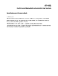
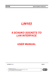
ERE S.n.c.
DAB-84: Instruction Manual
Revision: 3.0
DAB-84
Analog and Digital Data Acquisition and Reproduction Card
Instruction Manual
General Index..................................................................................................................................................... page
1
1.0 General Informations .................................................................................................................................. page
2
1.0.1 CE conformity....................................................................................................................................................... page
2
1.1 Communication Modes ............................................................................................................................... page
2
1.1.1 Point to Point communication.............................................................................................................................. page
1.1.2 Point to Multi-Point communication with ModBus protocol in RTU mode .................................................... page
2
3
2.0 Technical Data ............................................................................................................................................. page
5
2.0.1 Absolute Maximum Ratings ................................................................................................................................. page
2.0.2 Operating characteristics ...................................................................................................................................... page
5
5
3.0 Circuit description ....................................................................................................................................... page
6
3.0.1 µController section ................................................................................................................................................ page
3.0.2 Inputs and outputs digital interfaces and RS-485 Serial Port interface............................................................ page
3.0.3 Analog Inputs and Outputs interfaces ................................................................................................................. page
3.0.4 Supply section ........................................................................................................................................................ page
6
6
6
6
4.0 Connections .................................................................................................................................................. page
5.0 Configuration of the unit by Dipswitches and Jumper............................................................................. page
6
6
5.1 Master/Expansion configuration Jumper ............................................................................................................... page
5.2 Dipswitches ............................................................................................................................................................... page
5.2.1 Point to Point and Point to Multipoint address configuration ..................................................................... page
5.2.2 Automatic sending repetition time configuration.......................................................................................... page
5.2.3 “Safe Mode” configuration ............................................................................................................................. page
5.2.4 Communication Alarm functionality and its delay time configuration....................................................... page
6
7
7
8
8
8
6.0 Mechanical characteristics.......................................................................................................................... page
9
Page 1 of 9
ERE S.n.c.
DAB-84: Instruction Manual
Revision: 3.0
1.0 General Informations.
The DAB-84 card permits the Data acquisition, both analogue and digital, and the related reproduction respectively at
dedicated inputs and outputs.
The unit acquires the data and convert them in a message packet that may be sent to another similar unit through a RS485 Serial Port both in Wire and Wireless Mode, using an adequate Radiomodem.
The unit can also receive a message packet from the serial line and convert it into a analogue and/or digital data
available at the respective outputs.
The communication timing is expressly designed for the Wireless communication, naturally slower than cable communication, and the transmitted or received packet must be in the 9.600 bps, 8 data bits, No parity and 1 Stop bit
format. The serial port speed is internally set, and it’s generally suitable for both wire and wireless communication.
The DAB-84 card presents four Digital Inputs, two Analog Inputs and, consequently four Digital Outputs and two
Analog Outputs. A digital Alarm Output and the RS-485 Serial Port completes the unit.
The Alarm Output is activated by a fault in communication and it’s automatically reset when a normal
communication is restored. Please see the paragraphs 5.2.3 and 5.2.4 for the Alarm functionality and setting.
The DAB-84 card may be connected to others DAB-84 to expand both digital than analogue inputs, if necessary. The
connection between the principal unit, generally called Master, and the Expansion units is made by a flat-cable
connection, used also to connect the Master with a generic Auxiliary unit. A maximum of three expansion cards and
one Auxiliary card may be connected to the Master unit. To simplify the wiring, this flat cable includes the supply and
the manual reset lines besides the data line.
It’s possible realise both Point to Point than Point to Multipoint communication networks. In the last case a ModBus
protocol in RTU mode is implemented for communication.
The card configuration is realised by a Dipswitches bank and a selection Jumper.
The card is contained in an anodised Aluminium box covered with a transparent Plexi-glass panel. The metallic box is
electrically connected to the negative pole of the supply input. In according to the safety rules, this metallic box, and
consequently the negative pole of the supply, must be connected to ground.
In the bottom of the enclosure is mounted a metallic locking system to fix the device onto a Ω Din Guide.
NOTE: This device is not compliant with the Directives on the Human Operators Security so, it cannot be used
to drive any device, mechanical, electrical and so on, that may create a situation of risk to an operator.
1.0.1 CE conformity.
The DAB-84 card is in according to the CE directory under the following directives and related modifications:
2006/95/CE
“Low Voltage” Directive
2006/42/CE
“Machinery” Directive
2004/108/CE
“Electromagnetic Compatibility” Directive
Moreover, in the development of the homologation procedures, have been applied all the following norms and/or
technical requirements:
IEC 61326-1
EMC requirements
EN 61010-1
Safety requirements for electrical equipments
The DAB-84 card is CE compliant if all wires connected to all digital and analogue inputs and outputs and to the
supply input are shorter than 3 meters ( 3 yd. and 3.37 in.)
1.1 Communication Modes.
The DAB-84 card may be used to realise a telemetering/telecontrol network both in Point to Point and Point to
Multipoint modes.
The operating communication mode is selected by the Identification Address set into the card. If this address is equal
to 0, the unit works in Point to Point Mode while every address from 1 to 31 allows the Point to Multipoint Mode.
The address is set using the switches from 5 to 1 of the Dipswitches bank as explained in the § 5.2.1. The Master/
Expansion Jumper on the right side of the box configure the unit as Master, if single, or as Expansion, if connected
to a Master unit. The jumper configuration is explained in the § 5.1.
1.1.1 Point to Point communication.
Setting the Identification Address = 0 the unit works in Point to Point mode. In this case the network consists in two
units, one for each point. Both local and remote units must be configured as Master and, to avoid collisions during the
communication, in one of these the automatic repetition must be disabled, as explained in the § 5.2.2. If used, the
Expansion units must be in the same number in each side of the system.
In this operating mode a message exchange between the units is present to allow the mutual update of the outputs in
according with the related inputs level. The message length is of maximum 26 Bytes, if all expansion cards are
present.
The communication beginning may be originated by a status change in anyone of the digital inputs, by the periodic
repetition or by both of them. The Analogue Inputs cannot begin a communication so, if the DAB-84 cards are used
to measure only analogue parameters, a periodic repetition must be activated.
In a normal operating condition each sending causes an answer from the remote unit that must be correctly received
within a suitable timeout and, in its absence, the sending card comes into in a repetition procedure until a correct
Page 2 of 9
ERE S.n.c.
DAB-84: Instruction Manual
Revision: 3.0
answer is detected, after which it returns in the normal operating condition. The communication beginning from a status
change is the condition to obtain the minimum number of transmissions but may be not adequate to transfer the
analog parameters therefore, the better communication system is the periodic repetition, that may be configured with
cycles from 1 second to 1 hour as shown in the Table 8 of the § 5.2.2. In this operating mode at the supply switch-on,
or after a manual reset, the card waits 2 seconds, to stabilise the analog sensors, after which sends the first
communication. This moment is the initial time of the periodic repetition counter. If a correct answer is received from
the remote unit, the system will remain idle until the following sending, originated by the repetition time expiry, if no
one change occurs, or before, at the changing of anyone of the digital inputs. In this case the periodic repetition counter
is reset and restarts from this moment.
If, for any reason, a correct answer is not detected, the unit come into the repetition procedure, in which the message is
repeated in groups of three close transmissions, spaced of 30 seconds.
The repetition time interval between the three sending depends on the periodic repetition time selected in the
dipswitches bank. If this time is of 1 second, the repetition time interval is set to 1 second while for higher values it is
set to 4 seconds.
A communication fault Alarm is activated after 3 or 9 failed transmissions, depending on the dipswitch No. 10
setting, as explained in the § 5.2.4.
The expansion cards will be used if the required number of analog and/or digital inputs/outputs exceed the available on
a single card. In this way it’s possible to obtain until 8 analogue inputs and outputs and 16 digital inputs and outputs.
These additional cards must be configured as Expansions, using the lateral Jumper as explained in the § 5.1. The
serial ports RS-485 of these additional cards are inactive because the communication process is managed by the
Master unit so the serial ports of any expansion cards must be unconnected.
As the Master unit also the expansion unit has an Internal Identification Addres that may be set using the dip Nos. 5
and 4 of the dipswitches bank. It’s important to notice as this address is not the same of the address utilised by the
Master Unit but, in this case may be considered as a sub-address for the data sent into the correct expansion card. The
setting of these addresses is explained in the § 5.2.
Activating an input in the local unit the communication logic activates the homologous output in the remote unit and
vice-versa. This procedure is even valid when, in both local and remote units, are present one or more expansions.
1.1.2. Point to Multi-Point communication with ModBus protocol in RTU mode.
In a Point to Multipoint network, the central unit is a intelligent DTE such as a Computer or a PLC unit. The communication begins always from the central unit and all peripherals are used as slaves and cannot begin a communication. Generally the central unit uses a Polling to enquire each peripherals, using a ModBus protocol in RTU Mode.
In the simplest case each peripheral unit consist in one DAB-84 card that must be set with an Identification Addres
from 1 to 31, using the Dipswitches bank, as explained in the § 5.2.1.
A peripheral may be realised also with more than one DAB-84 card, if is necessary an higher number of analog or
digital inputs or outputs. These additional cards must be set as Expansions and must have an Internal Identification
Address set from 1 to 3, as specified in the § 5.2.
This Internal Identification Address is operating into the peripherals and it doesn’t appear in the address of the query
sent from the central unit of the network, but it permits the correct writing or reading of the inputs/outputs of the
expansion cards in each peripherals.
The functions available from the ModBus protocol used in the DAB-84 units are the following:
A – (0x01) Read Coils. It permits to read the status of the Digital Outputs. In system with a single DAB-84, the addressing range of this function covers the 0 to 3 range. Each additional expansion adds 4 addresses, so a complete
system operates with a function range from 0 to 15.
B – (0x02) Read Discrete Input. It permits to read the status of the Digital Inputs. The addressing range of this function, follows the same considerations explained for the Read Coils function.
C – (0x03) Read Holding Register. It permits to read of the values stored in both Digital to Analog converters that
drive the Analog Outputs. The addresses range of this function covers the 0 to 1 range and, as explained for the
previous functions, each additional expansion adds 2 addresses, so a complete system operates in the range 0 to 7.
D – (0x04) Read Input Register. It permits to read the value of the Analogue Inputs after the Analogue to Digital
conversion. The addresses range of this function follows the same rules explained for the Read Holding Register
function.
E – (0x05) Write Single Coil. It permits to write each Digital Outputs to permit its updating. The addresses range
follows the rules explained for the Read Coils function and, of course, to update each digital output it’s necessary to
write each register one at a time, specifying the correct address.
F – (0x06) Write Single Register. It permits to write the value stored in each Digital to Analogue converter to permit
its updating. The same rules explained for the addresses range of the Read Holding register function must be applied to this function and, of course, the register updating requires the indication of the address of the register to be
updated.
G – (0x0F) Write Multiple Coils. It permits to write an ensemble of Digital Outputs, sending only one message. Of
course, the addresses of the ensemble of Digital Output to be written must be specified into the message. The adPage 3 of 9
ERE S.n.c.
DAB-84: Instruction Manual
Revision: 3.0
dresses range of this function is the same of the Read Coils function .
H – (0x10) Write Multiple Register. Similarly to the Write Multiple Coils function, it permits to write an ensemble
of Digital to Analog converters, sending only one message. As above specified, the addresses of the ensemble of
DACs to be written must be indicated into the message. The addresses range of this function is the same of the
Write Single Register function.
The following Table 1 shown the equivalence between the address of the Discrete Inputs and Coils functions in the
ModBus protocol and the Digital Inputs and Outputs of the DAB-84 card.
Table 1: Equivalence between the addresses of the Discrete Inputs and Coils functions and digital I/O of the DAB-84.
Address
00
01
02
03
04
05
06
07
08
09
10
11
12
13
14
15
Digital Input
Input 1 of the Master
Input 2 of the Master
Input 3 of the Master
Input 4 of the Master
Input 1 of the 1st expansion card
Input 2 of the 1st expansion card
Input 3 of the 1st expansion card
Input 4 of the 1st expansion card
Input 1 of the 2nd expansion card
Input 2 of the 2nd expansion card
Input 3 of the 2nd expansion card
Input 4 of the 2nd expansion card
Input 1 of the 3rd expansion card
Input 2 of the 3rd expansion card
Input 3 of the 3rd expansion card
Input 4 of the 3rd expansion card
Digital Output
Output 1 of the Master
Output 2 of the Master
Output 3 of the Master
Output 4 of the Master
Output 1 of the 1st expansion card
Output 2 of the 1st expansion card
Output 3 of the 1st expansion card
Output 4 of the 1st expansion card
Output 1 of the 2nd expansion card
Output 2 of the 2nd expansion card
Output 3 of the 2nd expansion card
Output 4 of the 2nd expansion card
Output 1 of the 3rd expansion card
Output 2 of the 3rd expansion card
Output 3 of the 3rd expansion card
Output 4 of the 3rd expansion card
As appears from the above table, in presence of the only Master unit, only the addresses from 00 to 03 are valid while
the following ones are illegal and aren’t accepted. The addresses range of the ModBus function is automatically extended at the connection of one or more expansion cards, depending on their number. For example, the addition of one
expansion card automatically set the address range from 0 to 7, instead of from 0 to 3. The address assigned to the
expansion card must be the lowest possible, depending in the number of connected expansions, so, for example, the 1st
expansion card will have the address 1, the 2nd the address 2 and so on. This isn’t a request of the Master unit but, of
course, it’s the simplest method to assign the addresses.
The following Table 2 shows the equivalence between the addresses of the Input Registers and Holding Registers
functions, in the ModBus protocol and the Analog Inputs and Outputs of the DAB-84 card.
Table 2: Equivalence between the addresses of the Input and Holding Registers function and analog I/O of the DAB84.
Address
00
01
02
03
04
05
06
07
Analog Input
Input 1 of the Master
Input 2 of the Master
Input 1 of the 1st expansion card
Input 2 of the 1st expansion card
Input 1 of the 2nd expansion card
Input 2 of the 2nd expansion card
Input 1 of the 3rd expansion card
Input 2 of the 3rd expansion card
Analog Output
Output 1 of the Master
Output 2 of the Master
Output 1 of the 1st expansion card
Output 2 of the 1st expansion card
Output 1 of the 2nd expansion card
Output 2 of the 2nd expansion card
Output 1 of the 3rd expansion card
Output 2 of the 3rd expansion card
Also for these functions are valid all considerations explained for addresses assignment of the Discrete Inputs and Coils
function.
To utilise the DAB-84 cards with the ModBus protocol it’s necessary to install in the Central unit of the system a
dedicated software supporting this communication protocol. Are available a lot of versions of SCADA software,
supporting the ModBus protocol, configurable practically, for all the applications.
Page 4 of 9
ERE S.n.c.
DAB-84: Instruction Manual
Revision: 3.0
2.0 Technical Data.
In the following paragraph are listed the technical data of the DAB-84 card.
2.0.1 Absolute maximum ratings.
These values indicate the maximum value that each parameter can assume and their overcoming can damage
irreversibly the device or cause an operating condition beyond the safety condition with a considerable reduction of
the reliability of the whole system. The following Table 3 shows these maximum ratings.
Table 3: Absolute Maximum Rating of the DAB-84 card.
Parameter
VS
IS
IAN-OUT
IAN-INP
VO-AN
VO-AN-INS
IO-DIG
VO-DIG
VO-DIG-INS
VI-DIG
VI-DIG-INS
IO-RS485
VRS485-GND
Description
Supply Voltage
Current consumption
Output current of the analog sensor supply(1)
Analog Input current(2)
Voltage drop of each Analog Output(3)
Insulation between Analog Outputs and ground
Digital Outputs Current (max relay current)(4)
Voltage across Digital Outputs
Insulation between Digital Inputs and/or ground
Voltage at the Digital Inputs
Insulation between Digital Inputs and ground
RS-485 Serial Port current(5)
Voltage between RS-485 Serial Port and ground(5)
Value
+ 36 Vdc
500 mAdc
35 mAdc
60 mA continuous, 325 mA for 0.1 seconds
36 Vdc
50 Vdc
3 Adc/Aac
250 Vdc/Vac
250 Vac
30 Vdc/Vac
40 Vdc/Vac
85 mAdc
- 7 → +12 Vdc
NOTES:
(1) Available current to energise a two-wire 4-20mA transducer. The “no load” voltage is of +15,65 ± 0,25 Vdc with an internal resistance of 47 Ω.
(2) Each Analog Input is protected against overcurrents by a Fast Blow fuse of 50mA in 5 x 20 mm (0.2 x 0.8 inch) format. This fuse never must
be replaced with an higher current one, to avoid the destruction of the precision Current to Voltage converter.
(3) Maximum voltage across the Analog Outputs. Neglecting the voltage drops across the cables and the receiver input, this is the maximum
supply voltage of the analog output.
(4) The maximum current flowing into each Digital Output depends on the load typology:
In direct current are allowed the following values: 3A @ 30V / 0,35A @ 110V / 0,2A @ 220V.
In single-phase alternate current at 220Vac are allowed the following values: 3A @ cosφ=1 / 1A @ cosφ=0,2.
The maximum switchable power of a single phase “squirrel-cage” asynchronous motor is 100 VA.
(5) At nominal line load of 60 Ω. The interface chip determines both the maximum outgoing current and the maximum voltage between inputs and
ground.
2.0.2 Operating characteristics.
The following Table 4 shows the recommended operating characteristics of the DAB-84 card.
Table 4: Recommended operating characteristics of the DAB-84 card.
Parameter
VS
IS
PAV
VI-DIG
ZI-DIG
IAN-INP
ZAN-INP
VAN-INP
VO-DIG
IO-DIG
IO-AN
VO-AN
Baud Rate
Bit di Dati
Bit di Start
Parità
Description
Supply Voltage
Current consumption(1)
Idle power consumption(2)
Digital Inputs applicable Voltage(3)
Digital Inputs internal impedance(4)
Analog Input Current
Analog Input Impedance(5)
Analog Input Voltage
Digital Output Voltage
Digital Output Current
Analog Outputs Current(6)
Analog Outputs compliance(7)
Data Speed
Data Bits number
Start Bits number
Parity Bit value
Value
9 – 30 Vdc
≤ 500 mA
~ 720 mW
5 –24 V
2 kΩ
0–20 mA
78 Ω ±3Ω
0 – 1.62 V
220 Vac/dc
≤ 3 Aac/dc
4 –20 mA
8 – 30 Vdc
9.600 bps
8 bit
1 bit
N(othing)
Notes
Negative pole connected to ground (chassis).
Single card, all I/O activated at 8 Vdc supply.
Single card, all I/O idle.
AC/DC, separated inputs without common polarity.
Resistive with radio frequency internal filter.
Referred to ground, negative pole of the supply.
Across the input and ground.
Measured across input and ground.
Separated outputs protected by 275Vac varistor.
Depending on load type. See § 2.0.1 note [4].
Separated outputs and insulated respect ground.
Separated outputs and insulated respect ground.
1,200 to 19,200 bps on request.
E(ven) or O(dd) on request.
NOTES:
(1)
(2)
(3)
(4)
(5)
(6)
(7)
Due to the presence of the switching supply units the power consumption is practically constant respect to the supply voltage variations.
Indicates the power consumption with all inputs and outputs idle and with all transducer and serial port disconnected. At voltage V the idle current consumption can be calculated by I = P/V.
For example at V = 12 Vdc the related idle current is I = 0.72 / 12 = 0.06 A = 60 mAdc.
All alternating voltages and currents are intended RMS sinusoidal at main frequency of 50 or 60 Hz. Lower main frequency are not admitted.
The input impedance determines the current consumption of the digital input. It varies from 1.9 to 12 mAdc, allowing the input driving by an electronic device such as an “Open Collector”
transistor or an “Open Drain” Mosfet.
The analog input impedance is the sum of the sampling resistor (60Ω) plus the dc resistance of the noise filter inductor (~2.5Ω) and the dc resistance of the fuse (~15Ω). The sampling resistor
tolerance is 1%.
The analog outputs are linear in the 2 – 20 mA range so it’s possible to show the transducer failure condition or the Open current loop condition.
Each analog output is equivalent to a Current Generator and the VO-AN value indicates its operating voltage range. Due to the passive two-wire configuration, each output is energised by the
current loop therefore this value indicates the voltage drop across the output. This voltage, increased by the cable losses and the input voltage across the external current/voltage converter, determines the minimum supply voltage must be applied at each analog output.
Page 5 of 9
ERE S.n.c.
DAB-84: Instruction Manual
Revision: 3.0
3.0 Circuit description.
The DAB-84 unit contains a µController section, a Digital Input and Output Interface section, an Analog Input
and Output Interface section, and, finally, a Power Supply section, to energise all the others.
3.0.1 µController section.
It utilise a PIC18F4423 micro-controller energised at 5 Vdc, to allow the acquisition and reproduction of all digital
and/or analog data, the data communication through the RS-485 Serial Port directed to the external Radiomodem or
DTE, the data communication with the expansions and auxiliary card, if presents, and, finally, manage the ModBus
protocol.
3.0.2 Inputs and outputs digital interfaces and RS-485 Serial Port interface.
The digital inputs are connected through AC opto-couplers while the digital outputs and alarm output use a Relay
contact. A dedicated RS-485 interface chip is used in the communication port. The use of a relay contact into all digital
outputs permit the direct actuation of a small or medium loads, using the single phase AC mains at 115/230 Vac with
3 A of peak current.
3.0.3 Analog Inputs and Outputs interfaces.
The DAB-84 accept analog input signals in the 0-20 mA standard and reproduce the analog signals in the 2- 20 mA,
probably the most used system to carry analog signals in the industrial environment, for its great advantages respect to
the line attenuation, the noise interference and errors. The extension of the input current range and the linearity of the
analog output in the 2 –20 mA range allows the transfer of the Open Loop/Transducer failure condition as in a wired
system.
Each input contains a precision Current to Voltage converter, to translate the 0-20 mA into the 0 –5 Vdc required by
the 12 bit analog to digital converters into the micro-controller and is protected against over-current by a 50 mA fast
blow fuse. The input impedance of each input, referred to ground, is of 78 ±3 Ω and causes a input voltage drop of
1.56 Vdc ±60 mVdc.
The Analog Outputs receive the data to be send in digital format and convert it in analog 2-20 mA format using a 12
bit serial DAC and a high precision voltage to current converter. Since both analog outputs draws their supply from
the current loop the, the current never can be null. The minimum current in the loop can be measured after the
turning on transient or after a manual reset. This value is generally included in the 350 – 1,000 µA range.
Each analog output is insulated respect both the other and to the ground, and it’s equivalent to a passive two-wire
sensor, therefore an external supply source is required for their operation.
3.0.4 Supply section.
The utilisation of a switch-mode supply unit allows the card to accept a supply input voltage in the range from 8 to 36
Vdc. The negative pole of the supply is connected to ground and to the metallic chassis. The first internal switchmode supply reduce the input voltage to 5 Vdc to energise the micro-controller and digital interface sections. A second
switch-mode supply unit generate the supply voltage of the current to voltage converter and the external transducers.
The supply section is protected against polarity reversal and against over-current using a series diode and a fast blow
fuse. The energy consumption, depending on the status of digital outputs, is practically constant in the whole input
voltage range, and the maximum current consumption occurs at the minimum supply voltage.
4.0 Connections.
All supply, analog and digital inputs and outputs, alarm output and RS-485 serial port connections are realised with
screw connectors. The connectors for expansions and auxiliary cards are located on the sides of the box and they are a
male holder for flat-cable female connector. These flat-cable carries the communication line between the master unit
and the expansions/auxiliary card and the supply lines, in order to simplify the wiring.
NOTE: To avoid any problem of short-circuits between any input/output contact and/or between any contacts and the
ground, it’s important to use adequate wire termination, in particular if a stranded wire is used. During the wire
clamping, do not apply an excessive pressure and torque on the screw connector, to avoid damages to both the printed
circuit board and to the screw connector.
5.0 Configuration of the unit by Dipswitches and Jumper.
The operating mode of the DAB-84 card is selected by the Dipswitches bank and the lateral Jumper.
5.1 Master/Expansion configuration Jumper.
This jumper is located on the right side of the box, near the auxiliary card connector, and allows the configuration of the
card as Master or as Expansion, moving the short-circuit jumper to the required position.
If configured as Master, the card is completely independent and all its features are available, otherwise, as Expansion,
the card must be connected to a Master unit and some features as, for example the alarm output, the RS-485 serial
port communication, are inhibited and also the Dipswitches changes their functionality.
A single card must be always set as Master and this is the default setting after the production testing.
The following Table 5 on page 7 shows the operating condition of the DAB-84 card in both Master and Expansion
configuration.
Page 6 of 9
ERE S.n.c.
DAB-84: Instruction Manual
Revision: 3.0
Table 5: Features of the unit as function of the Master or Expansion configuration.
Jumper
position
MST
EXP
Operating
Mode
Master
Expansion
RS-485
Serial Port
Active
Inhibited
Addressing
Unit identifier from 0 to 31
Internal Identifier from 1 to 3
Repetition
Time
Active
Inhibited
Safe Mode
Alarm Delay
Available
Inhibited
Available
Inhibited
In the expansion mode the data communication between the Master unit and all expansion cards travels over a
communication port on the flat-cable while the RS-485 serial port is completely inhibited and must not be connected.
In the following paragraphs are explained the addressing, the safe mode and the alarm delay configuration.
5.2 Dipswitches.
This dipswitches bank allows the configuration when the card is set as Master. Each dip is active if it is in ON position and their functions are shown in the following Table 6.
Table 6: Function of each dipswitch.
Position
Dip
Dip
Dip
Dip
Dip
1
2
3
4
5
Dip 6
Dip 7
Dip 8
Dip 9
Dip 10
Binary
Weight
16
8
4
2
1
4
2
1
1
1
Function
Point to Point
OFF
OFF
OFF
OFF
OFF
Addressing
Addressing
Addressing
Addressing
Addressing
Time selection
Time selection
Time selection
Safe Mode
Alarm Delay
Master
Expansion
Point toMultipoint
Any modes
To be set depending
Not active
on the desired address.
Not active
Value range from 1 to
Not active
31, as explained in the Expansion Address:
following Table 7.
value range from 1 to 3
Set the repetition time
as explained in Table
8
Selectable
Selectable
Not active
Not active
Not active
Not active
Not active
Not active
5.2.1 Point to Point and Point to Multipoint address configuration.
The communication mode is selected by the address set in the card. This address is set by the dipswitches Nos. 1,2,3,4
and 5, as above explained. In this bank the LSB is the dipswitch No. 5 and the MSB is the No. 1. The following Table 7
shows the dipswitch set as function of the desired address. As is shown, the dipswitches Nos. 5 and 4 are used, in the
expansion card, as an internal address to select both inputs and outputs.
Table 7: Setting of the addresses dipswitches.
Address
0
1
2
3
4
5
6
7
8
9
10
11
12
13
14
15
16
17
18
19
20
21
22
23
24
25
Dip 1
OFF
OFF
OFF
OFF
OFF
OFF
OFF
OFF
OFF
OFF
OFF
OFF
OFF
OFF
OFF
OFF
ON
ON
ON
ON
ON
ON
ON
ON
ON
ON
Dip 2
OFF
OFF
OFF
OFF
OFF
OFF
OFF
OFF
ON
ON
ON
ON
ON
ON
ON
ON
OFF
OFF
OFF
OFF
OFF
OFF
OFF
OFF
ON
ON
Dip 3
OFF
OFF
OFF
OFF
ON
ON
ON
ON
OFF
OFF
OFF
OFF
ON
ON
ON
ON
OFF
OFF
OFF
OFF
ON
ON
ON
ON
OFF
OFF
Dip 4
OFF
OFF
ON
ON
OFF
OFF
ON
ON
OFF
OFF
ON
ON
OFF
OFF
ON
ON
OFF
OFF
ON
ON
OFF
OFF
ON
ON
OFF
OFF
Dip 5
OFF
ON
OFF
ON
OFF
ON
OFF
ON
OFF
ON
OFF
ON
OFF
ON
OFF
ON
OFF
ON
OFF
ON
OFF
ON
OFF
ON
OFF
ON
Page 7 of 9
Notes
Set Point to Point communication mode.
Multipoint mode / Expansion card internal address.
Multipoint mode / Expansion card internal address.
Multipoint mode / Expansion card internal address.
Multipoint mode.
Multipoint mode.
Multipoint mode.
Multipoint mode.
Multipoint mode.
Multipoint mode.
Multipoint mode.
Multipoint mode.
Multipoint mode.
Multipoint mode.
Multipoint mode.
Multipoint mode.
Multipoint mode.
Multipoint mode.
Multipoint mode.
Multipoint mode.
Multipoint mode.
Multipoint mode.
Multipoint mode.
Multipoint mode.
Multipoint mode.
Multipoint mode.
ERE S.n.c.
Address
26
27
28
29
30
31
DAB-84: Instruction Manual
Dip 1
ON
ON
ON
ON
ON
ON
Dip 2
ON
ON
ON
ON
ON
ON
Dip 3
OFF
OFF
ON
ON
ON
ON
Dip 4
ON
ON
OFF
OFF
ON
ON
Dip 5
OFF
ON
OFF
ON
OFF
ON
Revision: 3.0
Notes
Multipoint mode.
Multipoint mode.
Multipoint mode.
Multipoint mode.
Multipoint mode.
Multipoint mode.
5.2.2 Configuration of the repetition times in automatic sending condition.
In the Point to Point communication mode it’s available the periodic sending of a message to read or set the status of
all the analog and digital inputs and outputs. The time period is set by the dipswitches Nos. 8, 7 and 6 in which the dip
No. 8 is the LSB while the dip No. 6 is the MSB.
The following Table 8 shows the dipswitches set as function of the desired repetition time.
Table 8: Setting the time repetition dipswitches in Point to Point mode.
Repetition
Time
No repetition
1 second
5 seconds
30 seconds
1 minute
5 minutes
20 minutes
60 minutes
Dip 6
Dip 7
Dip 8
OFF
OFF
OFF
OFF
ON
ON
ON
ON
OFF
OFF
ON
ON
OFF
OFF
ON
ON
OFF
ON
OFF
ON
OFF
ON
OFF
ON
Notes
Starting message by the change in a digital input status(1).
Periodic sending and by digital input status change (1).
Periodic sending and by digital input status change (1).
Periodic sending and by digital input status change (1).
Periodic sending and by digital input status change (1).
Periodic sending and by digital input status change (1).
Periodic sending and by digital input status change (1).
Periodic sending and by digital input status change (1).
NOTE:
(1) The status change, originating a message transmission, may be occur on one of any digital inputs.
Independently from the Repetition time setting, the message is sent or at the repetition time expiry or when a digital
input changes its status. The Analogue inputs cannot start a message transmission.
To avoid collisions between messages in the Point to Point mode, one of the two cards must be set without repetition
time. In fact, if enabled, the two repetition times are equals or one can be chosen as an integer multiple of the other so,
the collision probability may be high.
The unit in which is set up the repetition time, must be placed into the control centre of the network. In this way the
Communication Alarm can be monitored and managed, under necessity.
The choice of the repetition time depends on the application and must be selected as function of the variation speed of
the measured parameter. For example if this parameter is analog, the repetition time must be sufficiently short to follow
correctly the input variations.
These time intervals are set into the firmware of the µController and may be suitable for the majority of the
applications. On request they may be changed to allow the maximum functionality.
5.2.3“Safe Mode” configuration.
The dipswitch No. 9 in ON position enables the “Safe Mode” operation. In this operating mode, at the fall of the
communication, all outputs are forced in the 0 condition, i.e. all digital outputs are “Open” and all analogue
outputs are set to 0, equivalent to an output current of 0 mA and, at the same time, the Communication Alarm output
is activated. As appears in the Table 8, the minimum time of 1 second is not compliant with the directives on the
Human Operators security, therefore this device must not be used to control any mechanical device that could create
a risk for the operator. In the following § 5.2.4 are shown more information on the Communication Alarm.
5.2.4 Communication Alarm functionality and its delay time configuration.
This paragraph it’s very important for the use of the DAB-84 unit because explains the functionality of the Communication Alarm and the reason because this device must not be used to drive any device that could create a risk for
human security. In the Point to Point mode both unit are able to show the Communication Alarm when, for any cause,
the communication between the units stops, for example for an interference in the radio channel. When a message is
sent, the sending unit waits an answer from the other unit, independently from the cause that originate this transmission
(repetition or status change of a digital input). If the communication is regular, an answer message comes from the
other unit, so that the repetition cycle proceeds under the time set by the dipswitches. If there isn’t an answer, the unit
repeats the message twice, waiting the answer and, in its absence, the sending unit sends again the message after 30
seconds. In absence of the answer this cycle is continuously repeated and, after 9 attempts and a total time in the range
from 1 minute and 9 seconds up to 1 minute and 36 seconds, depending on the selected repetition time, will be activated the Communication Alarm.
Page 8 of 9
ERE S.n.c.
DAB-84: Instruction Manual
Revision: 3.0
The dipswitch No. 10 set the delay time before the activation of the Communication Alarm. If the dip is in OFF
position, the alarm is activated after three attempts, otherwise in ON position, it is activated after the 9th. If the
repetition time is less than 1 minute, the dip No. 10 must be in the OFF position, to avoid excessive delays.
Because the Communication Alarm controls the status of both analog and digital outputs, if the Safe Mode is
enabled, appears evident as the minimum time before the activation of the Safe Mode is of about 3 or 12 seconds.
This time is not compliant with the safety directives because is too long, therefore the DAB-84 must not be used as
control system of any devices, mechanical, electrical and so on, that could create risks for the operator safety. The
Communication Alarm is automatically deleted when is restored a regular communication, so all outputs, forced to 0
if the Safe Mode is enabled, come back to the correct value, restoring the system operation. As well for this reason, the
DAB-84 must not be used to control devices that may be potentially dangerous for the operator safety.
6.0 Mechanical characteristics.
The whole apparatus is closed in an anodised Aluminium box with a Plexi-glass cover fixed with four knurled knobs.
On the bottom side of the box a DIN Guide bracket is present to allow a simple insertion in the related Ω DIN guide.
The weight of the apparatus is 15.16 ± 0.3 oz. av.
The following Figure 1 shows the outline drawings of the DAB-84.
Fig. 1: DAB-84 outline drawings.
Page 9 of 9