1
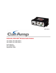
North Group LTD. User Manual – Smart OS Positioning Opertative System 1 User Manual – Smart OS Positioning Opertative System Copyright Copyright 2007-2013 North. © 2007 North Group LTD. All rights reserved. North is trademark of North Group LTD. All other trademarks are the property of their respective owners, 2007. Trademarks North Group LTD. All product and brand names mentioned in this publication are trademarks of their respective holders. 2 User Manual – Smart OS Positioning Opertative System Content 1. 2. Operation.......................................................................................................................... 4 1.1 Main screen ........................................................................................................... 4 1.2 Screens diagram .................................................................................................... 6 Main menu........................................................................................................................ 7 2.1.1 Receiver mode ....................................................................................................... 7 2.1.2 PPS Recording........................................................................................................ 8 2.1.3 Sat Accuracy .......................................................................................................... 8 2.1.4 Settings ................................................................................................................. 9 2.1.4.1 Base known ........................................................................................................ 9 2.1.4.2 Autocaster.......................................................................................................... 9 2.1.4.3 CORS ................................................................................................................ 10 2.1.4.4 MOBILE NETWORK ........................................................................................... 10 2.1.4.5 PPS filename .................................................................................................... 10 2.1.5 UHF Channel ........................................................................................................ 11 2.1.6 Display Setup....................................................................................................... 12 2.1.7 Sound Setup ........................................................................................................ 12 2.1.8 Tilt Setup ............................................................................................................. 12 2.1.9 Quit setup ........................................................................................................... 12 2.1.10 Power OFF ........................................................................................................... 12 Appendix A............................................................................................................................. 13 Appendix B ............................................................................................................................. 25 Appendix C ............................................................................................................................. 26 RTK Base Setup................................................................................................................ 26 North Group LTD. RTK Rover Setup .............................................................................................................. 28 3 User Manual – Smart OS Positioning Opertative System 1. Operation The North SmaRTK is a GNSS RTK receiver designed to be the simplest to use, and to be compatible with most platforms and communication protocols. The SmaRTK receiver has a mainframe that operates with the SmartOS Operative System on board, that is designed for a flexible and simple use, with the main feature of being able to be upgraded to add new features over time on the same hardware. Long-Press (3 seconds) used To turn on the SmaRTK Long-Press the button. The display will start, show the serial number and SmartOS version, and then enter to the Main Screen. 1.1 Main screen The Main Screen shows the current RECEIVER MODE of the receiver, that will be the last one that the receiver was set to. Also it will show the number of locked satellites, the battery/power status, and the Communication status. 4 1 2 3 North Group LTD. 1. Can se the SmaRTK mode, to see more Smartk modes see "1.2.2 Receiver mode" 2. The constellations are divided into: L: Locked GPS (Navstar) Satellites. G: Locked GLONASS Satellites. C: Locked COMPASS Satellites 4 User Manual – Smart OS Positioning Opertative System 3. Data transmitter indicator “Hourglass” Icon indicates that the Mobile Network is connecting “Bars” Icon: Indicator of the Mobile Network strength “Waves” Icon, Indicator of the UHF Radio-modem operation TX: Indicates that the SmaRTK is Transmitting correction data. RX: Indicates that the SmaRTK is Receiving correction data. RDY: Indicates that the SmaRTK is Ready to record Raw Data for Static PostProcessing. REC: Indicates that the SmaRTK is Recording Raw Data for Static Post-Processing. 4. Battery level indicator North Group LTD. : Shows the Battery level up to 100%. : Charging Icon, indicates that the external power is connected. : Battery Empty Icon, indicates that the battery is charging. : Battery Full Icon, indicates that the battery is fully charged. 5 User Manual – Smart OS Positioning Opertative System North Group LTD. 1.2 Screens diagram 6 User Manual – Smart OS Positioning Opertative System 2. Main menu 2.1.1 Receiver mode -PPS Recording: The RTK recorded format crude raw data “NOR” to internal memory as static point. The file will download and convert to RINEX for post-processing. Bluetooth is on. For more information see the “2.1.2 PPS Recording” -Rover Network: The RTK transmits correctly data (in RTCM 3 format). This mode would be displayed and you will see an “hourglass” icon. The internal modem is connecting to the CORS server through the Mobile Network. Bluetooth is on. . -Rover AutoCaster: The RTK is set to Rover Mode. GPRS modem is On. The Rover receives corrections via GPRS from AutoCaster server. Bluetooth is on. -Rover UHF: The RTK is set to Rover Mode. UHF modem is On in receive mode. The UHF receives corrections from radio modem on mode transparent. Bluetooth is on. -Base AutoCaster: The RTK is set to Base Mode. GPRS modem is On. The GPRS modem transmit corrections to "Auto caster" server in RTCM3 format. -Base UHF INT 2W: North Group LTD. The RTK is set to Base Mode. Turn On the UHF set to transmission mode with an output of 2W. -Base UHF EXT .5W: The RTK is set to Base Mode. Turn On the UHF set to transmission mode with an output of 0.5W. This mode is to put the “U-CAST 25/45w Amplifier” in the TNC port. -Base Serial: The RTK is set to Base Mode. This mode is for connection to a radio from another brand (Pacific Crest, etc..) Or PC to operate as CORS. 7 User Manual – Smart OS Positioning Opertative System 2.1.2 PPS Recording For post process is necessary to have the SmaRTK in "PPS Recording" mode. You will have on your main screen as follows: The SmaRTK is ready to use to post process. Now, if you want to start post processing, press the button to start the post process, appear as follows: To stop the post-processing, please press the button. Appear as follows: For more information to downloading data for post-processing view the user manual "Quick Operation Guide Smart-Os". 2.1.3 Sat Accuracy -SAT ACCURACY: North Group LTD. P0.0 H0.0 V0.0. PDOP, HDOP and VDOP respectively. 8 User Manual – Smart OS Positioning Opertative System 2.1.4 Settings 2.1.4.1 Base known -BASE KNOWN LAT: 00°00'00.0000” N Can be “N or S”. -BASE KNOWN LONG: 00°00'00.0000” W Can be “W or E”. -BASE TX PROTOCOL: Indicates the data transmission protocol of the base. 2.1.4.2 Autocaster -AUTOCASTER IP: Server Address Auto-Caster, can be IP o Web direction. -AUTOCASTER PORTS: North Group LTD. Ports Tx and Rx from Auto-caster server 0000/0000. 9 User Manual – Smart OS Positioning Opertative System 2.1.4.3 CORS - CORS CASTER IP: Server Address CORS, can be IP o Web direction. -CORS TX PORT: Ports Tx from CORS server 0000/0000. -CORS USER: Shows the CORS users. -CORS PASSWORD: Shows the CORS password users. -CORS STREAM: Shows the correction data format. 2.1.4.4 MOBILE NETWORK -MOBILE NET APN testAPN: Displays the “Access Point Name” Mobile network. -MOBILE NET User test User: Shows the Mobile Network users. -MOBILE NET Pass, test Password: North Group LTD. Shows the Mobile Network Password. 2.1.4.5 PPS filename -PPS Filename: Show the name set to PPS file. 10 User Manual – Smart OS Positioning Opertative System 2.1.5 UHF Channel Choose between the three bands in the range of 410-470 MHz. Please check the appropriate frequency to work according to the requirements of your country. UHF radio transceiver with 48 pre-selected channels and custom channels setup. Find the option "Main menu >> UHF channel" on main menu, when selected, you can choose between 3 ranges of bands. Each band contains 16 channels assigned to specific frequencies: UHF Channel UHF Channel Frequencies 450 – 470 MHz UHF Channel Frequencies 430 – 450 MHz #0 420.0125 MHz #0 460.0125 MHz #0 440.0125 MHz #1 420.5125 MHz #1 460.5125 MHz #1 440.5125 MHz 419.5125 MHz #2 459.5125 MHz #2 439.5125 MHz #3 421.0125 MHz #3 461.0125 MHz #3 441.0125 MHz #4 419.0125 MHz #4 459.0125 MHz #4 439.0125 MHz #5 421.5125 MHz #5 461.5125 MHz #5 441.5125 MHz #6 418.5125 MHz #6 458.5125 MHz #6 438.5125 MHz #7 422.0125 MHz #7 462.0125 MHz #7 442.0125 MHz #8 418.0500 MHz #8 458.0500 MHz #8 438.0500 MHz #9 422.5125 MHz #9 462.5125 MHz #9 442.5125 MHz #10 418.0125 MHz #10 458.0125 MHz #10 438.0125 MHz #11 423.0125 MHz #11 463.0125 MHz #12 417.5125 MHz #12 457.5125 MHz #13 423.5125 MHz #13 463.5125 MHz #14 417.0125 MHz #14 457.0125 MHz #15 420.0000 MHz #15 460.0000 MHz #2 North Group LTD. Frequencies 410 – 430 MHz #11 443.0125 MHz #12 437.5125 MHz #13 443.5125 MHz #14 437.0125 MHz #15 440.0000 MHz 11 User Manual – Smart OS Positioning Opertative System 2.1.6 Display Setup -Always ON: the display will remain on all the time. The duration of the battery is reduced. -Auto OFF 1 min.: the display will remain on 1 min. The duration of the battery is extended. -Auto OFF 10 min: the display will remain on for 10 min. the duration of the battery is the average. 2.1.7 Sound Setup -Sound ON: The sound is active -Sound OFF: the sound has been deactivated. 2.1.8 Tilt Setup -Tilt setup set zero: Press multifunctional button to set zero the horizontal and vertical angle. 2.1.9 Quit setup Exit the menu and returns to main screen. North Group LTD. 2.1.10 Power OFF The receiver turns “OFF”. 12 User Manual – Smart OS Positioning Opertative System Appendix A NMEA 0183 output This appendix describes the formats of the subset of NMEA-0183 messages that are available for output by the receiver. For a copy of the NMEA-0183 Standard, go to the National Marine Electronics Association Website at www.nmea.org NMEA-0183 Outputs When NMEA-0183 output is enabled, a subset of NMEA-0183 messages can be output to external instruments and equipment connected to the North receiver serial port. These NMEA-0183 messages let external devices use selected data collected or computed by the receiver. All messages conform to the NMEA-0183 version 3.01 format. All begin with $ and end with a carriage return and a line feed. Data fields follow comma (,) delimiters and are variable in length. Null fields still follow comma (,) delimiters but contain no information. An asterisk (*) delimiter and checksum value follow the last field of data contained in an NMEA0183 message. The checksum is the 8-bit exclusive OR of all characters in the message, including the commas between fields, but not including the $ and asterisk delimiters. The hexadecimal result is converted to two ASCII characters (0–9, A–F). The most significant character appears first. North Group LTD. The following table summarizes the set of NMEA messages supported by the receiver, and shows the page where detailed information about each message can be found. 13 User Manual – Smart OS Positioning Opertative System Message AVR GGA GSA GST GSV HDT PTNL,GGK PTNL,GGK_SYNC PTNL,PJK PTNL, PJT PTNL, VGK PTNL, VHD RMC ROT VTG ZDA Function Time, yaw, tilt, range, mode, PDOP, and number of SVs for Moving Baseline RTK Time, position, and fix related data GNSS DOP and active satellites Position error statistics Number of SVs in view, PRN, elevation, azimuth, and SNR Heading from True North Time, position, position type and DOP values Time, synchronized position, position type and DOP values Local coordinate position output Projection type Time, locator vector, type and DOP values Heading Information Position, Velocity, and Time Rate of turn Actual track made good and speed over ground UTC day, month, and year, and local time zone offset To enable or disable the output of individual NMEA messages, do one of the following: • Create an application file in the GPS Configurator software that contains NMEA output settings and then send the file to the receiver. • Add NMEA outputs in the Serial outputs tab of the GPS Configurator software and then apply the settings. 1. Common Message Elements Each message contains: • A message ID consisting of $GP followed by the message type. For example, the message ID of the GGA message is $GPGGA. North Group LTD. • A comma • A number of fields, depending on the message type, separated by commas • An asterisk • A checksum value 14 User Manual – Smart OS Positioning Opertative System Below is an example of a simple message with a message ID ($GPGGA), followed by 13 fields and a checksum value: $GPGGA,172814.0,3723.46587704,N,12202.26957864,W,2,6,1.2,18.893,M,-25.669,M,2.0,0031*4F 1.1 Message values The following values can be found in NMEA messages that the receiver generates. Latitude and longitude Latitude is represented as ddmm.mmmm and longitude is represented as dddmm.mmmm, where: • dd or ddd is degrees • mm.mmmm is minutes and decimal fractions of minutes Direction Direction (north, south, east, or west) is represented by a single character: N, S, E, or W. Time Time values are presented in Universal Time Coordinated (UTC) and are represented as hhmmss.cc, where: • hh is hours, from 00 to 23 • mm is minutes • ss is seconds • cc is hundredths of seconds North Group LTD. 2. NMEA Messages When NMEA-0183 output is enabled, the following messages can be generated. 2.1 AVR. - Time, Yaw, Tilt, Range for Moving Baseline RTK The AVR message string is shown below, and the follow table describes the message fields. $PTNL,AVR,181059.6,+149.4688,Yaw,+0.0134,Tilt,,,60.191,3,2.5,6*00 15 User Manual – Smart OS Positioning Opertative System Field 1 2 3 4 5 6 7 8 9 10 11 Meaning U TC of vector fix Yaw angle in degrees Yaw Tilt angle in degrees Tilt Reserved Reserved Range in meters Quality indicator: 0: Fix not available or invalid 1: Autonomous GPS fix 2: Differential carrier phase solution RTK (Float) 3: Differential carrier phase solution RTK (Fix) 4: Differential code-based solution, DGPS PDOP Number of satellites used in solution 2.2 GGA. - Time, Position, and Fix Related Data An example of the GGA message string is shown below. Followed table describes the message fields. $GPGGA,172814.0,3723.46587704,N,12202.26957864,W,2,6,1.2,18.893,M,-25.669,M,2.0,0031*4F North Group LTD. Field 1 2 3 4 5 6 Meaning UTC of position fix Latitude Direction of latitude: N: North S: South Longitude Direction of longitude: E: East W: West GPS Quality indicator: 0: Fix not valid 1: GPS fix 2: Differential GPS fix 16 User Manual – Smart OS Positioning Opertative System 4: Real Time Kinematic, fixed integers 5: Real Time Kinematic, float integers Number of SVs in use, range from 00 to 12 HDOP Orthometric height (MSL reference M: unit of measure for height is meters Geoid separation M: geoid separation is measured in meters Age of differential GPS data record, Type 1 or Type 9. Null field when DGPS is not used. Reference station ID, ranging from 0000 to 1023. A null field when any reference station ID is selected and no corrections are received. 7 8 9 10 11 12 13 14 2.3 GSA. - GNSS DOP and active satellites An example of the GSA message string is shown below. Following Table describes the message fields. $GPGSA,<1>,<2>,<3>,<3>,,,,,<3>,<3>,<3>,<4>,<5>, <6>*<7><CR><LF> North Group LTD. Field 1 2 3 4 5 6 7 Meaning Mode 1, M = manual, A = automatic Mode 2, Fix type, 1 = not available, 2 = 2D, 3 = 3D PRN number, 01 to 32, of satellite used in solution, up to 12 transmitted PDOP-Position dilution of precision, 0.5 to 99.9 HDOP-Horizontal dilution of precision, 0.5 to 99.9 VDOP-Vertical dilution of precision, 0.5 to 99.9 Checksum 2.4 GST . - Position Error Statistics An example of the GST message string is shown below. Following table describes the message fields. $GPGST,172814.0,0.006,0.023,0.020,273.6,0.023,0.020,0.031*6ª 17 User Manual – Smart OS Positioning Opertative System Field 1 2 3 4 5 6 7 8 Meaning UTC of position fix RMS value of the pseudorange residuals (includes carrier phase residuals during periods of RTK(float) and RTK(fixed) processing) Error ellipse semi-major axis 1 sigma error, in meters Error ellipse semi-minor axis 1 sigma error, in meters Error ellipse orientation, degrees from true north Latitude 1 sigma error, in meters Longitude 1 sigma error, in meters Height 1 sigma error, in meters 2.5 GSV. - Satellite Information The GSV message string identifies the number of SVs in view, the PRN numbers, elevations, azimuths, and SNR values. An example of the GSV message string is shown below. Following table describes the message fields. $GPGSV,4,1,13,02,02,213,,03,-3,000,,11,00,121,,14,13,172,05*67 North Group LTD. Field 1 2 3 4 5 6 7 8-11 12-15 16-19 Meaning Total number of messages of this type in this cycle Message number Total number of SVs visible SV PRN number Elevation, in degrees, 90° maximum Azimuth, degrees from True North, 000° to 359° SNR, 00–99 dB (null when not tracking) Information about second SV, same format as fields 4–7 Information about third SV, same format as fields 4–7 Information about fourth SV, same format as fields 4–7 2.6 HDT. - Heading from True North The HDT string is shown below, and the following table describes the message fields. $GPHDT,123.456,T*00 18 User Manual – Smart OS Positioning Opertative System Field 1 2 Meaning Heading in degrees T: indicates heading relative to True North 2.7 PTNL, GGK. - Time, Position, Position Type, DOP An example of the PTNL,GGK message string is shown below. The following table describes the message fields. $PTNL,GGK,172814.00,071296,3723.46587704,N,12202.26957864,W,3,06,1.7,EHT-6.777,M*48 Meaning UTC of position fix Date Latitude Direction of latitude: N: North S: South 5 Longitude 6 Direction of Longitude: E: East W: West 7 GPS Quality indicator: 0: Fix not available or invalid 1: Autonomous GPS fix 2: Differential, floating carrier phase integer-based solution, RTK(float) 3: Differential, fixed carrier phase integer-based solution, RTK(fixed) 4: Differential, code phase only solution (DGPS) 8 Number of satellites in fix 9 DOP of fix 10 Ellipsoidal height of fix 11 M: ellipsoidal height is measured in meters Note – The PTNL, GGK message is longer than the NMEA-0183 standard of 80 characters North Group LTD. Field 1 2 3 4 2.8 PTNL, GGK_SYNC. - Time, Synchronized Position, Position Type, DOP The PTNL,GGK_SYNC message has the same format as the PTNL,GGK message, but outputs Synchronized 1 Hz positions even in Low Latency mode. An example of the PTNL,GGK_SYNC message string is shown below. The following table describes the message fields. 19 User Manual – Smart OS Positioning Opertative System $PTNL,GGK_SYNC,172814.00,071296,3723.46587704,N,12202.26957864,W,3,06,1.7,EHT6.777,M*48 Field 1 2 3 4 Meaning UTC of position fix Date Latitude Direction of latitude: N: North S: South 5 Longitude 6 Direction of Longitude: E: East W: West 7 GPS Quality indicator: 0: Fix not available or invalid 1: Autonomous GPS fix 2: Differential, floating carrier phase integer-based solution, RTK(float) 3: Differential, fixed carrier phase integer-based solution, RTK(fixed) 4: Differential, code phase only solution (DGPS) 8 Number of satellites in fix 9 DOP of fix 10 Ellipsoidal height of fix 11 M: ellipsoidal height is measured in meters Note – The PTNL,GGK_SYNC message is longer than the NMEA-0183 standard of 80 characters. 2.9 PTNL, PJK. - Local Coordinate Position Output An example of the PTNL,PJK message string is shown below. Table A.9 describes the message fields. North Group LTD. $PTNL,PJK,010717.00,081796,+732646.511,N,+1731051.091,E,1,05,2.7,EHT-28.345,M*7C Field 1 2 3 4 5 Meaning UTC of position fix Date Northing, in meters Direction of Northing will always be N (North) Easting, in meters 20 User Manual – Smart OS Positioning Opertative System 6 7 Direction of Easting will always be E (East) GPS Quality indicator: 0: Fix not available or invalid 1: Autonomous GPS fix 2: Differential, floating carrier phase integer-based solution, RTK(float) 3: Differential, fixed carrier phase integer-based solution, RTK(fixed) 4: Differential, code phase only solution (DGPS) Number of satellites in fix DOP of fix Ellipsoidal height of fix M: ellipsoidal height is measured in meters 8 9 10 11 2.10 PTNL, PJT. - Projection Type An example of the PTNL,PJT message string is shown below. Following table describes the message fields. $PTNL,PJT,NAD83(Conus),California Zone 4 0404,*51 Field 1 2 2.11 Meaning Coordinate system name (can include multiple words) Projection name (can include multiple coordinates) PTNL, VGK. - Vector Information An example of the PTNL,VGK message string is shown below. Following Table describes the message fields. North Group LTD. $PTNL,VGK,160159.00,010997,-0000.161,00009.985,-0000.002,3,07,1,4,M*0B Field 1 2 3 4 5 6 Meaning UTC of vector in hhmmss.ss format Date in mmddyy format East component of vector, in meters North component of vector, in meters Up component of vector, in meters GPS quality indicator: 0: Fix not available or invalid 1: Autonomous GPS fix 2: Differential carrier phase solution RTK(float) 3: Differential carrier phase solution RTK(fix) 21 User Manual – Smart OS Positioning Opertative System 4: Differential code-based solution, DGPS Number of satellites if fix solution DOP of fix M: Vector components are in meters 7 8 9 2.12 PTNL, VHD. - Heading Information An example of the PTNL,VHD message string is shown below. Following table describes the message fields. $PTNL,VHD,030556.00,093098,187.718,-22.138,-76.929,-.015,0.033,0.006,3,07,2.4,M*22 Field 1 2 3 4 5 6 7 8 9 10 11 North Group LTD. 2.13 Meaning UTC of vector in hhmmss.ss, ddmmyy format Date in mmddyy format Azimuth Azimuth/Time Vertical angle Vertical/Time Range Range / Time Quality indicator: 0: Fix not available or invalid 1: Autonomous GPS fix 2: Differential carrier phase solution RTK(float) 3: Differential carrier phase solution RTK(fix) 4: Differential code-based solution, DGPS Number of satellites used in solution PDOP RMC. - Position, Velocity, and Time The RMC string is shown below, and following table describes the message fields. $GPRMC,123519,A,4807.038,N,01131.000,E,022.4,084.4,230394,003.1,W*6A Field 1 2 Meaning UTC of position fix Status A=active or V=void 22 User Manual – Smart OS Positioning Opertative System 3 4 5 6 7 8 9 Latitude Longitude Speed over the ground in knots Track angle in degrees (True) Date Magnetic variation The checksum data, always begins with * 2.14 ROT. - Rate of Turn The ROT string is shown below, and Table A.14 describes the message fields. $GPROT,35.6,A*4E Field 1 2 2.15 Meaning Rate of turn, degrees/minutes, "–" indicates bow turns to port A: Valid data V: Invalid data VTG. - Actual Track Made Good Over and Speed Over Ground An example of the VTG message string is shown below. The following table describes the message fields. North Group LTD. $GPVTG,,T,,M,0.00,N,0.00,K*4E Field 1 2 3 4 5 6 7 8 Meaning Track made good (degrees true) T: track made good is relative to true north Track made good (degrees magnetic) M: track made good is relative to magnetic north Speed, in knots N: speed is measured in knots Speed over ground in kilometers/hour (kph) K: speed over ground is measured in kph 23 User Manual – Smart OS Positioning Opertative System 2.16 ZDA. - UTC Day, Month, And Year, and Local Time Zone Offset An example of the ZDA message string is shown below. The following table describes the message fields. $GPZDA,172809,12,07,1996,00,00*45 Field Meaning 1 UTC 2 Day, ranging between 01 and 31 3 Month, ranging between 01 and 12 4 Year 5 Local time zone offset from GMT, ranging from 00 to ±13 hours 6 Local time zone offset from GMT, ranging from 00 to 59 minutes Fields 5 and 6 together yield the total offset. For example, if field 5 is –5 and field 6 is North Group LTD. +15, local time is 5 hours and 15 minutes earlier than GMT. 24 User Manual – Smart OS Positioning Opertative System Appendix B RTCM Output Generated messages Messages that are generated when you select a specific RTCM version are as follows. These messages are in the same order as they appear in the GPS Configuration software. For the details of the contents of individual messages, refer to the RTCM documentation. Selection Version 2 USCG 9-3 RTCM/RTK 2.2+2.3 RTK Only 2.2+2.3 RTCM/RTK 2.3 RTK Only 2.3 RTCM/RTK 2.2 RTK Only 2.2 RTCM/RTK 2.1 RTK Only 2.1 RTCM/RTK 3.00 Message 1 3 3 1 3 3 1 1 1 3 3 3 3 22 59 9-3 18 18 18 18 18 18 18 18 19 19 19 19 19 19 19 19 22 22 23 23 23 24 24 24 22 22 22 22 22 1004 1006 1008 59 59 59 59 59 59 1013 Message scheduling North Group LTD. The frequency at which messages are generated when they are enabled in a base receiver is as follows. Type 1 3 9-3 18 19 22 23 24 59-sub,13 1004 1006 1008 1013 Frequency Every second The 10th second after the first measurement, then every 10 seconds after that Every second Every second Every second The 5th second after the first measurement, then every 10 seconds after that The 4th second after the first measurement, then every 10 seconds after that The 4th second after the first measurement, then every 10 seconds after that The 5th second after the first measurement, then every 10 seconds after that Every second Every 10 seconds Every 10 seconds Every 300 seconds 25 User Manual – Smart OS Positioning Opertative System Appendix C Setting up RTK system RTK Base Setup Prerequisites You need a tripod and a tribrach to install the base. To power the radio, you need a standard 12-V DC battery (A car, motorcycle, or other kinds can be used). Datalink UHF Radiomodem North Group LTD. Mount the different items shown as the picture 1) Put tripod on a location with known coordinates or unknown coordinates, attach receiver to tribrach. 2) Precisely level and center the instrument 26 User Manual – Smart OS Positioning Opertative System 3) Set the transmitting antenna and radio: using pole support is better, rise the antenna as high as possible, and then put the radio at suitable position. WARNING: There is sequence for the cables linking to Radiomodem 1. Affix the antenna cable to the radio. 2. Affix the Power cable to the radio 3. Affix the data cable to the radio 4) Make sure the connection is right, and then switch on the radio and mainframe. GSM/GPRS Model North Group LTD. Mount the different items shown as the picture For GPRS mode is not necessary to set up the radio antenna 27 User Manual – Smart OS Positioning Opertative System RTK Rover Setup Prerequisites If a radio link is used with the base, your rover should normally have been fitted with the radio module that matches the reception band covered by the radio transmitter used at the base. If a GPRS connection is used, rover should normally have been fitted with the SIM card that will allow it to perform a network connection. Remove the rear cover, this gives access to an electronic card on which you can insert the SIM card as shown on the picture. Radio Link 1) Install the pole, rover and receiving antenna, then power on the mainframe. North Group LTD. 2) Install the bracket, fix the handheld to the bracket, open the handheld to connect the Bluetooth, then you can do the setting of the instrument. As a standard feature, the receiver incorporates a built-in GSM modem. Mount the different items as shown on the above Figure, including the receiver, the range pole, and the field terminal with its mounting bracket. 28 User Manual – Smart OS Positioning Opertative System How to measure the antenna height? The height of receiver is 78mm, the diameter is 208mm, and the height from the center of the sealed rubber ring to the bottom is 47mm. North Group LTD. The antenna height is conventionally defined as the vertical height from the phase centre to the ground surveyed point (the distance “h” in the follow fig). It is not possible to measure it directly: you have to measure other reachable heights (the distances “a” and “s” in fig). The distance “a” is the vertical height from the ground to the mainframe’s bottom (bottom of antenna), the distance “s” is measured from the ground surveyed point to the middle of the rubber ring and is called “bottom of notch”. You have to choose the measuring method according to the used software: 29 User Manual – Smart OS Positioning Opertative System Information/Sales: [email protected] Technical Support: North Group LTD. [email protected] Copyright 2007-2013 North. © 2007 North Group LTD. All rights reserved. 30