1
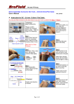
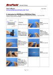
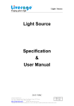
We make FTTX easy. User’s Manual Rev. 2011A Fiber Meter Fiber Meter Specification & User Manual Page 1 of 6 We make FTTX easy. User’s Manual Rev. 2011A Fiber Meter 1.1 Description: The Fiber Meter is mainly used for checking the signal output power of the optical communication equipment in fiber optic networks. It measures the average power of a continuous light beam which emits from the equipments or other optic sources. It measures power in both 850 nm / 1300 nm (Multimode) and 1310 nm / 1490 nm / 1550 nm (Singlemode) respectively. The Fiber Meter consists of a solid state InGaAs photo diode, signal power measurement circuitry, and a 2 Digit s / 3 Digits LED display. Users just connect a fiber cable between the transmission port of the equipment and the universal interface on the Fiber Meter. (Or connect to other light source) The product will show the exact amount of the received power value (in dBm). The universal connector can be used for all the most common fiber interfaces such as ST / SC / FC and it is suitable to test both Singlemode and Multimode cables. With an optical 2.5 mm to 1.25 mm adapter, users can even test for 1.25 mm fiber interface. 1.2 Features: Robust & handy design with LED digits reading. Easy to check Multimode 850 nm / 1300 nm output power. Easy to check Singlemode 1310 nm / 1490 nm / 1550 nm output power. Universal 2.5 mm to 1.25 mm adaptor for SC / ST / FC to LC or MU 2 Digits / 3 Digits resolution and Low Voltage Battery warning LED display. Measuring power in Multimode 850 nm / 1300 nm within -40 dBm ~ +5 dBm ranges. Measuring power in 3 Digits Singlemode 1310 nm / 1490 nm / 1550 nm within -40 dBm ~ +5 dBm ranges. The correspondence of power in dBm and µW can be consulted by the following table: Page 2 of 6 We make FTTX easy. User’s Manual Rev. 2011A Fiber Meter dBm µW dBm µW dBm µW dBm µW -30 1 -18 15.8 -6 251 -29 1.3 -17 19.9 -5 316 -40 0.1 -28 1.6 -16 25.1 -4 398 -39 0.126 -27 2.0 -15 31.6 -3 501 -38 0.158 -26 2.5 -14 39.8 -2 631 -37 0.199 -25 3.2 -13 50.1 -1 794 -36 0.251 -24 4.0 -12 63 0 1000 -35 0.316 -23 5.0 -11 79.4 +1 1259 -34 0.398 -22 6.3 -10 100 +2 1585 -33 0.501 -21 7.9 -9 125 +3 1995 -32 0.631 -20 10 -8 158 +4 2512 -31 0.794 -19 12.5 -7 199 +5 3162 2. Specification Wavelength ( Multimode) Optical Power Range ( Multimode) 2 Digits -30 dBm ~ -10 dBm Optical Power Range ( Multimode) 2 Digits -40 dBm ~ +5 dBm Wavelength 850 nm / 1300 nm ( Singlemode) 1310 nm / 1490 nm / 1550 nm Optical Power Range ( Singlemode) 2 Digits -30 dBm ~ -3 dBm Optical Power Range ( Singlemode) 3 Digits -40 dBm ~ +5 dBm Battery AAA 1.5V X 2 Resolution ( 2 Digits / 3 Digits ) 1 dB / 0.1 dB Fiber Connector Display Universal Type (Diameter:2.5mm) ( 2 digits / 3 digits ) 2 digits / 3 digits LED Operating Temp. 0℃~ 50℃ Storage Temp. 0℃~ 70℃ 3. Operating Instructions Page 3 of 6 We make FTTX easy. User’s Manual Rev. 2011A Fiber Meter 4 2 3 1 4 3 1 2 To touch / bend the Dust Cap to open the connector 1. Dust Cap : to prevent dirt contaminates the PD 2. Switch : Wavelength choosing switch. 3. LED : figures shown input power indicator dBm and Lower Power Battery indicator ( Cb ). 0 1 CA 2 3 Cb 4 5 6 Low 7 8 9 -4.0 dBm +3.0 dBm 4. Button : pressing to Turn On / Turn Off the Meter. Page 4 of 6 High We make FTTX easy. User’s Manual Rev. 2011A Fiber Meter 5. Pen Clip : a design to fasten the tool while put inside pocket. 6. Battery Lid : to open to change batteries. 7. Linchpin : a mechanical design to lock the Battery Lid. 1. The Fiber Meter is powered by two pieces 1.5 V AAA batteries 2. INITIAL CALIBRATION: To keep the Dust Cap closed, then turn on the Fiber Meter by pressing the Button. The LED will show “CA” means the Initial Calibration is proceeding, after about 3 seconds LED will show “Lo” and it means the Fiber Meter complete the Initial calibration successfully and can start to work. 3. Lift the front dustproof up and insert one end of the fiber cable to the universal connector or direct insert to an output connector of fiber devices or Power Source. 4. Switch the slide switch to 850 nm / 1300 nm position ( for measuring Multimode fiber ) or to 1310 nm / 1490 nm / 1550 nm position ( for measuring Singlemode fiber ). The LED figure shows the actual receiving input power values. 5. The “Lo” will display when actual receiving power is under measuring range. While the input power is higher than measuring range, then “ Hi” is displayed in the LED indicator. 6. To measure the power loss of a fiber cable, you need a steady power source. For example, light source output power is -20 dBm after a fiber cable transmission and the -10 dBm tested directly from the LD power source, this means there is at least 10 dB power losses after this fiber transmission. 7. When the LED shown “Cb“ (Check Battery) , this means that the batteries are almost drained out and in low voltage status therefore it is suggested that you need to replace the batteries right away. 8. Do not touch the fiber’s interface to avoid dirt containing the connector. 9. Keep the fiber connector capped at all the time when the device is not in use. 10. With proper cleaning tools to clean the fiber before testing, obtain the right tests results and make the device service longer. 4. Maintenance & Trouble Shootings This tool requires no maintenance in stead of periodic battery charges. Like any other electronic equipment, this tool should be kept away from water, high damp, dust, electricity, and environments of extreme temperature. Do not drop this tool on hard surface. Modifying internally any of this tool components can cause a malfunction and will invalid the manufacturer’s warranty. Page 5 of 6 We make FTTX easy. User’s Manual Rev. 2011A Fiber Meter “CA” means the Initial Calibration is proceeding, “Cb“ means to Check Battery. It is suggested to replace the batteries. “ Hi” means the input power is higher than measuring range . “Lo” means receiving power is lower than measuring range. “…” It is suggested to Reset the Power Meter. 5. Warranty The manufacturer warrants this product to be free of defects in workmanship and materials for a period of 1 year after purchase. This warranty (excluding batteries) is solely limited to the repair and replacement of original parts, which are defective in workmanship of materials. All other costs should be the sole responsibility of the owner. This warranty does not cover any defects, damage, and deterioration due to misuse, alteration, or negligence. 6. Ordering Information: P/N Discreption Wavelength ITP-18 Fiber Meter (Singlemode) 1310 nm / 1490 nm / 1550 nm 3 digits ITP-19 Fiber Meter (Multimode) 850 nm / 1300 nm 2 digits ITP-20 LC adapter for Fiber Meter NA NA ITP-21 MU adapter for Fiber Meter NA NA 7. Service Contacts If you have further questions for the use of our product, please contact us at the followings. BroField Technology Inc. NO, 6, LN 40, SEC 1. CHU-MEI RD, CHUTUNG, HSINCHU, 310 TAIWAN e-mail: [email protected] web: www.brofield.com TEL +886-3-5833517 FAX +886-3-5827018 Page 6 of 6 Digits