1
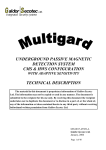
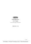
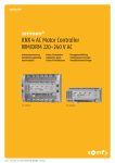
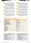
Operating Instructions
TMH 064 / TMU 064
TMH 065 / TMU 065
Turbomolecular Drag Pumps
PM 800 308 BE/E (0001)
INDEX
Page
Page
1. Safety Instuctions ................................... 3
4. Operations ................................................ 9
1.1. For Your Orientation........................................................... 3
4.1. Before Switching ON......................................................... 9
1.2. Pictogram Definitions........................................................ 3
4.2. Switching ON...................................................................... 9
2. Understanding The Pumps
TMH/TMU 064, TMH/TMU 065 ............... 4
4.3. Heating (Only Pumps With Heating Sleeves))............... 9
2.1.
Main Features ................................................................... 4
4.4. Switching OFF And Venting.............................................. 9
2.2.
Differences Between The Pump Types ........................ 4
4.5. Shutting Down For Longer Periods ............................... 10
3.
Installation.............................................. 5
3.1.
Preparations For Installation .......................................... 5
5. What To Do In Case Of
Breakdowns ? ........................................ 10
Assembling The Pump, Connecting The
6. Maintenance.......................................... 11
High Vacuum Side ............................................................ 5
6.1. Replacing The Lubricant Reservoir............................... 11
3.2.
Fitting The Splinter Shield ............................................... 6
3.3.
3.4.
Connecting The Fore-Vacuum Side............................... 6
Connecting The Cooling Unit .......................................... 6
Water Cooling (Accessory)............................................. 6
Air Cooling (Accessory)................................................... 7
3.5.
Connecting The Casing Heating Unit ............................ 7
3.6.
Connecting The Venting Valve ....................................... 8
3.7.
Connecting The Electronic Drive Unit ........................... 8
3.8.
Connecting The Sealing Gas Valve ............................... 8
Reset .................................................................................... 9
7. Service.................................................... 12
8. Technical Data....................................... 13
8.1. Dimensions Diagram ....................................................... 14
9. Spare Parts ............................................ 14
10. Accessories .......................................... 16
Declaration of Contamination..................... 17
Manufacturer’s Declaration........ (last page)
2
1. Safety Instuctions
☞ Read and follow all the instructions in this manual.
☞ Inform yourself regarding:
– Hazards which can be caused by the pump;
– Hazards which can arise in your system;
– Hazards which can be caused by the medium being
pumped.
☞ Avoid exposing any part of your body to vacuum.
☞ Comply with all safety and accident prevention
regulations.
☞ Check regularly that all safety requirements are being
complied with.
☞ Do not operate the pump with open high vacuum flange.
☞ Do not carry out any unauthorised conversions or
modifications on the pump.
☞ When returning the pump to us please note the shipping
instructions.
☞ Use at least four bracket screws to connect the high
vacuum flange (ISO-flange).
☞ Fix down the pump in accordance with the instructions on
installation.
☞ Do not disconnect the pump cable during operations.
☞ When the pump is open, disconnect the electronic drive
unit from the mains.
☞ After switching off the pump, disconnect the electronic
drive unit only once the rotor is at rest.
☞ When working on the pump, only open the high vacuum
flange once the rotor is at rest.
☞ When using sealing gas, limit the pressure in the hose
connection to 2 bar via the overflow valve.
☞ If a heater is in use temperatures of up to 120 °C can be
present in the area of the high vacuum flange. Take care to
avoid burns !
☞ During operations, temperatures of up to 65 °C can arise in
the lower part of the turbopump. Take care to avoid burns!
☞ Keep leads and cables well away from hot
surfaces ( > 70 °C).
1.1. For Your Orientation
Instruction in the text
➡ Working instruction:
here, you have to do something.
Symbols used
The following symbols are used throughout in all illustrations.
High vacuum flange
Fore-vacuum flange
Venting connection
Cooling water connection
Air cooling
Electric connection
Sealing gas connection
Position numbers
The same pump and accessory parts have the same position
numbers in all illustrations.
1.2. Pictogram Definitions
Danger of burns from touching hot parts.
Danger of an electric shock.
Danger of personal injury.
Danger of damage to the pump or to the system.
Modifications reserved.
Danger of injury from rotating parts.
3
2. Understanding The Pumps
TMH/TMU 064 und TMH/TMU 065
2.1. Main Features
Turbomolecular Drag Pump TMH 064
1
2
3
5
6
High vacuum flange
Fore-vacuum flange
Cooling water connection
Power connection
Rubber feet
1
2
3
5
6
Cooling
Standard:
Alternative:
Convection cooling.
Air or water cooling as an
accessory.
Integrated excess temperature safety feature:
Electronic drive unit reduces rotor rotation
speed to zero.
Bearings
High vacuum side: Wear free permanent magnetic
bearing.
Fore-vacuum side: Oil circulatory lubricated bearings with
ceramic balls.
4
Proper use
– The Turbomolecular Pumps may only be used for the purpose of generating vacuum.
– The turbopumps may only be used to pump those media
against which they are chemically resistant. For other
media the operator is required to qualify the pumps for the
processes involved.
– If the process produces dust, the maintenance intervals
must be specified accordingly and sealing gas must be
used.
– The turbomolecular pump may only be operated with a
PFEIFFER Electronic Drive Unit and relevant cables.
– The turbopump must be connected to a backing pump in
accordance with Section 3.3.
Improper use
The following is regarded, inter alia, as improper:
– The pumping of explosive or corrosive gases.
– Operating the pumps in areas where there is a danger of
explosion.
– The pumping of gases and vapours which attack the materials of the pumps.
– The pumping of corrosive gases without sealing gas.
– The pumping of condensating vapours.
– Operations involving impermissibly high levels of gas
loads.
– Operations with improper gas modes.
– Operations involving too high levels of heat radiation
power (see Section 8. ”Technical Data”).
– The use of accessories which are not named in this
manual or which have not been agreed by the
manufacturer.
Improper use will cause all claims for liability and guarantees
to be forfeited.
2.2. Differences Between The Pump Types
Feature
TMH 064
TMH 064
TMU 064
TMU 065
High vacuum flange
ISO-K
CF-F
High vacuum seal
Viton
Metal
Attainable final
pressure
< 1 · 10-8 mbar
< 1 · 10-10 mbar
(with baking-out)
(without baking-out)
3. Installation
3.1. Preparations For Installation
Do not carry out any unauthorised conversions
or alterations to the turbopump.
– The maximum permissible rotor temperature of the pump is
90 °C. If the vacuum chamber or parts in the vacuum
chamber are heated must be fitted if necessary, suitable
shielding in the vacuum chamber before the turbopump
(constructional suggestions available on request).
– Only remove the blank flange from the high and fore-vacuum side immediately before connection.
– On Turbopumps the lubricant reservoir is already fitted and
filled.
– Where magnetic fields of > 4 mT are involved suitable
shielding must be provided (available on request).
– If the pump is baked out, the heating sleeve and the body
of the pump must be insulated to prevent burns from
accidental contact.
– In the event of a sudden standstill of the rotor, torques of
up to 260 Nm (TMH/U 064) and 270 Nm (TMH/U 065) can
arise and these must be taken up by the turbopump and
frame. Pumps must be anchored as follows:
– ISO flange with 4 bracket screws, or
– CF flange with the complete set of M8 screws, or
– Underside of the pump with 4 screws M5,
screws quality 8.8.
Connecting via a vibration compensator
The maximum permissible temperature at the
vibration compensator is 100 °C.
Where a vibration compensator is in use, a freely suspended
turbopump can be flanged onto the vacuum chamber.
Additional fastening is unnecessary.
Directly flanging the pump
Permissible installation positions for the turbopump
3.2. Installing The Pump,
Connecting The High Vacuum Side
Important
The utmost cleanliness must be observed when fitting all high
vacuum parts. Unclean components prolong the pumping
time.
Using the splinter shield
The use of a splinter shield in the high vacuum flange
protects the turbopump against foreign bodies coming from
the vacuum chamber but does reduce the volume flow rate of
the pump by approximately 15%.
For fitting splinter shields please refer to “Fitting the splinter
shield”
The high vacuum side can be flanged directly to the vacuum
chamber or via a bellows or a vibration compensator (accessory).
Connecting via a bellows
If the high vacuum side is to be flanged via a bellows, the turbopump must be secured for example via the holes on the
underside of the turbopump (see ”Dimensions”)
The fastening must be able to withstand the torque referred
to in Section 3.1.
The maximum loading capacity of the high vacuum flange is 200 N (equivalent to 20 kg).
Assymetric loading on the high vacuum flange
must be avoided.
With horizontal pump installation and oil-sealed backing
pumps (e.g. rotary vane pumps) the fore-vacuum flange of the
turbopump must be aligned vertically downwards (maximum
deviation ±20°), otherwise the turbopump could become
dirty.
No forces from the piping system must be
allowed to act on the pump where turbopumps
are anchored.
Suspend or support all pipes to the pump.
5
Fitting The Splinter Shield
Connecting the backing pump
Insert the splinter shield in the high vacuum flange in such a
way that the corrugation of the strainer points outwards.
➡ Bend the clamping lugs slightly outwards so that
subsequently the splinter shield is seated firmly in the high
vacuum flange (to avoid noise).
➡ Insert the splinter shield in the high vacuum flange while
pressing the clamping lugs slightly inwards.
➡ Press the outer ring of the splinter shield up to the limit
stop point in the high vacuum flange.
21 Backing pump
22 Vacuum safety valve
23 Suction line
DN 16 ISO-KF
G1/4”
22
21
Inserting the splinter shield
V
23
≤ 5 mbar
12 Splinter shield
12a Clamping lug
12
H
3.4. Connecting The Cooling Unit
12a
The turbopump is convection-cooled as standard.
Where ambient temperatures exceed 30 °C or with heated
systems, the pump should be operated with air or water cooling.
Water cooling is mandatory where temperatures
exceed 35 °C.
Water Cooling (Accessory)
3.3. Connecting The Fore-Vacuum Side
Backing pump:
Recommendation:
Vacuum pressure ≤ 5 mbar
Oil-Free Diaphragm Pump or Rotary
Vane Vacuum Pumps from the PFEIFFER
range (note installation position,
turbopump, see Section 3.2.).
See “Accessories” for the cooling water parts set.
Connecting parts set for cooling water
16 USIT ring
18 Hose nozzle
19 Hollow screw
Connecting the backing pump
All connections of the fore-vacuum line: with the usual small
flange components or hose screw connections.
Be sure to conduct away the exhaust gases
from the backing pump. Do not reduce the free
cross section of the fore-vacuum flange with
following components.
The exhausted process gases and vapours can
represent a health hazard and can also be environmentally damaging.
Comply with all the gas manufacture's safety
instructions.
➡ Fit the vacuum safety valve in the fore-vacuum line (in
PFEIFFER rotary vane vacuum pumps already integrated).
This prevents vacuum chamber venting via the backing
pump.
➡ With rigid pipe connections: Fit bellows in the connecting
line to reduce vibration.
➡ Backing pump power connection: See operating
instructions for the electronic drive unit.
6
Cooling water either
– From the cooling water mains, or
– from Recycled Water Cooling Unit TZK with closed
circuit.
Cooling water from the cooling water mains
Cooling water must be filtered to prevent deposits forming in
the pump.
Minimum cooling water requirements:
Mechanically clean, optically clear, no turbidity, no sediment,
chemically neutral, temperature > dew point.
Oxygen content:
Chloride content:
Carbonate hardness:
Potassium permanganate consumption:
Carbon dioxide:
Ammonia:
pH-value:
max
4 mg/kg
max.
100 mg/kg
max.
10 °dH
max.
10 mg/kg
Undetectable
Undetectable
7–9
Fore-line over pressure:
Minimum flow rate at gas load max.:
max.
6 bar
50 l/h bei 15 °C
Connecting to the water mains
➡ Fit dirt trap (accessory) in the fore-line.
➡ Using circlips, connect fore-line to one of the two cooling
water connections.
➡ Fit Cooling Water Monitor TCW 002 (accessory) in the
return line.
➡ Connect return line to the other turbopump cooling water
connection.
➡ Tighten all circlips and ensure hose lines are seated firmly.
➡ Tighten the hollow screws on the cooling water
connection to a torque of 20 Nm.
Air Cooling (Accessory)
See “Accessories” for air cooling parts set.
Air cooling permissible only if ambient temperature < 35 °C.
Ensure adequate air circulation and ventilation.
Fitting the air cooling
➡ Place turbopump on its high vacuum flange (blank flanged
so that the sealed surface is not damaged).
➡ Unscrew rubber feet from the base of the pump.
➡ Screw air cooling onto the holder with 4 M5 screws and
spring washers onto the turbopump. The fan must be
parallel to the axis fore-vacuum connection - venting
connection. See illustration below.
Fitting the air cooling
36
36a
37
38
Fan
Buffer
Holder
M5 screw with spring washers (4x)
Cooling from the water mains
3
31
32
33
34
Cooling water connection
Fore-line
Return line
Dirt trap
Cooling Water Monitor TCW 002
3
33
31
32
Power connection, air cooling
Please see the operating instructions for the Electronic Drive
Unit TCP 015.
34
Cooling with the recycled Water Cooling Unit TZK
(Accessory)
Connecting to the TZK
A dirt trap in the pipeline is not permissible.
All other steps as for connection to the water mains.
Cooling with the recycled Water Cooling Unit TZK
3 Cooling water connections
34 Cooling Water Monitor TCW 002 in the return line
35 Recycled Water Cooling Unit TZK
3
TZK
34
3.5. Connecting The Casing Heating Unit
The attainment of final pressures is accelerated when turbopumps and vacuum chambers are baked out.
The heating duration is dependent on the degree of dirt and
on the required final pressure level. The heating duration
should be at least 4 hours.
➡ Secure heating sleeve beneath high vacuum flange.
High temperatures are generated when
turbopumps and vacuum chambers are baked
out. There is a danger of burns resulting from
touching hot parts, even after the casing heating
has been switched off.
Ideally, the heating sleeve, pump casing and vacuum
chamber should be insulated during installation. Do not touch
the heating sleeve, pump casing and vacuum chamber during
the baking out process.
35
7
3.6. Connecting The Venting Valve
3.7. Connecting The Electronic Drive Unit
– The venting valve provides automatic venting in the event
of a power failure and switching off.
Voltages of >100 V can be present on the open
electrical contacts on a slowing down pump.
There is danger of an electrical shock if the
contacts are touched.
Disconnect the plug to the electronic drive unit
only once the pump is completely at rest and the electronic
drive unit has been disconnected from the mains.
Venting
Valve
Control Unit
Electronic
Drive
Venting Procedure
After Switch OFF Or
Power Failure
TSF 010
not
required
independent
Immediate;
Venting valve remains open
TSF 012
not
required
TCP 015/
380/121
Delayed (venting begins at
approx. 20% of the rated
rotation speed) venting valve
remains open
TVF 012
TCF/TCV 103
TCP 380/121
(not with
TCP 015)
Delayed: adjustable
(with TCS 304)
➡ Plug in connecting cable between the electronic drive unit
and the turbopump. For details please see the operating
instructions for the electronic drive unit.
Connecting electronic drive unit to the turbopump
Fitting the venting valve
Please refer to the operating instructions of the respective
unit. Use Adapter PM 033 737-T where flange size DN 10-KF is
involved.
50
51
52
53
Electronic Drive Unit TCP
Male multipoint connector
Connecting cable
Bayonet plug --> turbopump
50
51
Connecting the venting valve
53
41
42
43
44
52
Venting control unit
Venting valve
Connecting hose
Drier TTV 001
41
3.8. Conncting The Sealing Gas Valve
42
43
44
Power connection
Please refer to the operating instructions of the respective
unit.
8
To protect the pump, particularly where corrosive or dust producing processes are involved, it is necessary to use sealing
gas. Connection is made via the sealing gas valve (please see
”Accessories”).
Please refer to Operating Instructions PM 800 229 BE for
details on installling the sealing gas valve and adjusting the
sealing gas flow.
Please refer to Section 8.1. ”Dimensions Diagram” for the
sealing gas connection.
4. Operations
4.1. Before Switching ON
Turbopump rotors rotate at high speed. When
the high vacuum flange is open there is a danger of injury and of damage to the pump caused
by objects falling into the pump.
Therefore never operate the pump with open
high vacuum flange.
➡ With water cooling: Open cooling water supply and check
flow.
TMH/TMU 065/064 with TCP 121 or TCP 380:
In the invent of malfunction, the voltage supply of the motor is
switched off via the contact K2. The reset function is activated by:
➡ Disconnecting the mains voltage for a time ≥ 2 seconds,
e.g. by pressing the mains switch S1.
➡ Operating an externally connected ”reset” pushbutton S3
for a time ≥ 2 seconds.
Please note:
In the ”reset” function is activated via an external reset pushbutton, the TCP must be energized.
4.2. Switching ON
➡ Switch on the turbopump with switch S1 on the power
pack unit.
4.3. Heating (Only Pumps With Heating
Sleeves)
The heating period is dependent on the level of contamination
and the required final pressure. Heat for at least four hours.
Electronic drive unit switches (schematically)
S1 Turbopump ON/OFF
S2 Heating ON/OFF
➡ Switch on turbopump heating via switch S2 on the
electronic drive unit.
Please take account of the notes in Section 3.5.
S2
S1
– With air cooling, the cooling fan is also switched on by the
electronic drive unit.
– If Pumping Station Control Unit TCS 303/304 is involved,
turbopump, backing pump and the water recycling unit (if
fitted) are started together with switch S1 on the
electronic drive unit.
Take care when pumping hazardous gases.
Comply with all the gas manufacturer's safety
instructions.
Reset
4.4. Switching Off And Venting
To avoid contamination occurring when switching off, the
pump should be vented with dry venting gas before shutdown.
➡ Close vacuum safety valve in the fore-vacuum line.
➡ Switch off both turbopump and backing pump at the same
time with switch S1 on the electronic drive unit.
➡ Open locking screw or venting valve in the venting
connection (with PFEIFFER venting valves and pertinent
control units the turbopump is vented automatically).
➡ With water cooling: Shut off water supply.
The minimum venting time to atmospheric
pressure is 30 seconds.
TMH/TMU 064/065 with TCP 015:
When the TCP 015 detects a fault, the motor power is
switched off. After the fault has been corrected, the pump
does not accelerate automatically. The ”reset” command
required for this may be executed by:
➡ Switching off via S1 for a time ≥ 5 seconds.
➡ Connecting the remote ”Fault reset” input, X5/b6 to X5/z2
(0 volt) for a time ≥ 5 seconds via an external switch.
➡ Transmitting a corrosponding command via the RS 232 C
interface.
9
4.5. Shutting Down For Longer Periods
Vacuum pumps are sometimes used to pump
aggressive or hazardous gases. There is a danger of personal injury resulting from coming into
contact with process gases. Before removing a
turbopump from the system, first:
– Vent the turbopump with a neutral gas or dry air;
– Ensure that there is no residual process gas in the system
nor in the supply lines.
If the turbopump is to be shut down for more than a year:
➡ Remove turbopump from the system.
➡ Replace lubricant reservoir (see Section 6.1.).
Please note: Lubricant TL 011 must no longer be used after
2 years of non operations.
➡ Close high vacuum flange and evacuate pump via the forevacuum flange.
➡ Vent turbopump via the venting connection with nitrogen
or dry air.
➡ Close fore-vacuum and venting connections by blank flanging.
➡ Place the pump vertically on its rubber feet.
➡ In rooms with moist or aggressive atmospheres, the turbopump must be air-sealed in a plastic bag together with a
bag of dessicant, e.g. silicagel.
Important:
If the pump has been shut down for 3 years a bearing change
must be carried out (please get in touch with PFEIFFER
service).
5. What To Do In Case Of Breakdowns?
Problem
Possible Cause
Remedy
Pump doesn't start
• Power supply interrupted
• Check fuse in the
electronic drive unit
• Check plug contacts on the pump
and the electronic drive unit
• Check supply lines
Pump doesn't attain rated
rotation speed;
Pump cuts out during operations
• Fore-vacuum pressure to high
• Leak or too much gas
•
•
•
•
•
• Rotor stiff because bearing defective
• Run-up phase in the Electronic
Drive Unit TCP too short
• Thermal overloading caused by
– Water cooling: Flow not safe
guarded
– Air cooling: Air supply restricted
– Fore-vacuum pressure too high
– Ambient temperature too high
Pump doesn't attain final pressure
• Pump dirty
• Leak in vacuum chamber,
lines or pump
Unusual operating noises
10
• Bearings damaged
• Rotor damaged
• Splinter shield (if fitted)
not seated firmly
Check backing pump function
Check seals
Seek leak and repair
Reduce process gas feed
Check bearings (noisy ?):
Request PFEIFFER to replace
• Extend run-up phase setting time
•
•
•
•
Ensure free flow
Ensure adequate air supply
Reduce fore-vacuum pressure
Reduce ambient temperature
• Bake out pump
• If seriously contaminated:
Request PFEIFFER to clean
• Seek leak, starting with vacuum chamber
• Repair leak
• Inform PFEIFFER of need for repair
• Inform PFEIFFER of need for repair
• Check splinter shield: Press clamping
lugs away from each other
(see Section 3.2.)
6. Maintenance
Important:
No liability for personal injury nor material damage will be
accepted for damages and operational interruptions which
have been caused by improper maintenance; in addition, all
guarantees become invalid.
You can replace the lubricant reservoir yourself
(see Section 6.1.).
Your pump can be cleaned on the spot if it is not very dirty.
Your local PFEIFFER Center can advise you regarding
cleaning procedures and any other maintenance and service
work which might be necessary.
6.1. Replacing The Lubricant Reservoir
Replace the lubricant reservoir at least once every year.
Where extreme operating or unclean processes are involved
please get in touch with your PFEIFFER Center for
advice.
➡ Switch off turbopump, vent to atmospheric pressure (see
Section 4.4.) and allow to cool as necessary.
➡ If necessary remove the turbopump from the system.
➡ Using a broad screwdriver unscrew the locking cap 90 from
the underside of the pump; be careful with the O-ring 91.
➡ Lever out the lubricant reservoir with the help of two
screwdrivers.
Remove locking cap and take out lubricant reservoir
90
91
92
93
Locking cap
O-ring
Lubricant reservoir
O-ring
90
91
92
H
93
92
H
➡ Remove dirt from the pump and locking cap with a clean,
fluff-free cloth.
➡ Insert new lubricant reservoir 92, which comes filled with
Lubricant TL 011, up to the O-ring 93.
➡ Screw in locking cap 90 with O-ring 91. The locking cap
will bring the lubricant reservoir into the correct axial position.
Lubricant reservoirs can contain toxic
substances from the media pumped.
Dispose of lubricant reservoirs in accordance
with local regulations.
11
7. Service
Do make use of our service facilities
In the event that repairs are necessary a number of options
are available to you to ensure any system down time is kept to
a minimum:
– Have the pump repaired on the spot by our Service
Engineers;
– Return the pump to the manufacturer for repairs;
– Replace the pump.
Local PFEIFFER representatives can provide full details.
Before returning:
➡ Please attach a clearly visible notice "Free of harmful substances" (both on the unit and also on the delivery note
and any accompanying letters).
"Harmful substances" are defined in the current, local regulations and in the U.S.A. as "materials in accordance with the
Code of Federal Regulations (CFR) 49 Part 173.240 Definition
and Preparation".
We will carry out the decontamination and invoice this work
to you if you have not attached this note. This also applies
where the operator does not have the facilities to carry out
the decontamination work. Units which are contaminated
microbiologically, explosively or radioactively cannot be
accepted as a matter of principle.
Fill out the contamination declaration
➡ In every case the "Contamination Declaration" must be
completed diligently and truthfully.
➡ A copy of the completed declaration must accompany the
unit: any additional copies must be sent to your local
PFEIFFER Center.
Please get in touch with your local PFEIFFER representatives
if there are any questions regarding contamination.
12
Decontaminate units before returning or possible disposal. Do not return any units which are
microbiologically, explosively or radioactively
contaminated.
Returning contaminated units
If contaminated have to be returned for maintenance/repair,
the following instructions concerning shipping must be followed:
➡
➡
➡
➡
Neutralise the pump by flushing with nitrogen or dry air.
Seal all openings to the air.
Seal pump or unit in suitable protective foil.
Ship units only in appropriate transport containers.
Please note:
Repair orders are carried out according to our general conditions of sale and supply. If repairs are necessary, please send
the unit to your nearest PFEIFFER Service Center.
Contact addresses and service hotline
Contact addresses and service hotlines can be found on the
back cover of these operating instructions.
8. Technical Data
Feature
Unit
Connection nominal diameter
Inlet
TMH 064
DN 40 ISO-KF
DN 63 ISO-KF
DN 63 CF-F
DN 16 ISO-KF/G 1/4”
G 1/8”
Outlet
Venting connection
Max. permissible rotor temperature
Permissible heat radiation power
Electronic Drive Unit
Nominal rotation speed
Standby rotation speed
Run-up time (up to 90%
rated rotation speed)
Noise level
Final pressure, backing pump
Volume flow rate for:
Nitrogen N2
Helium He
Hydrogen H2
Max. gas throughput2)
N2
He
H2
Final pressure3)
with diaphragm vacuum pump
with rotery vane vacuum pump
TMH 065
TMH 065
TMU 065
DN 40 ISO-KF
DN 63 ISO-KF
DN 63 CF-F
DN 16 ISO-KF/G 1/4”
G 1/8”
°C
W
90
4
90
4
1/min
1/min
TCP 0151)
90 000
60 000
TCP 0151)
90 000
60 000
min
dB (A)
mbar
2,5
< 50
≤5
3
< 50
≤5
l/s
l/s
l/s
30
40
20
Compressen ratio for:
N2
He
H2
Max. fore-vacuum pressure
N2
He
H2
TMH 064
TMU 064
53
42
31
30
40
34
56
48
36
> 109
7 · 104
4 · 103
> 1010
1 · 107
1 · 105
mbar
mbar
mbar
14
10
6
18
15
8
mbar l/s
mbar l/s
mbar l/s
1,1
1,5
1
0,8
1,0
1.2
mbar
mbar
< 1 · 10-8
< 2 · 10-10
< 1 · 10-9
< 1 · 10-10
TL 011
convection
TL 011
convection
Lubricant
Cooling type, standard
Cooling water consumption with
water at 15 ˚C
Cooling water temperature
Permissible ambient temperature
with air cooling
Heating power consumption
l/h
˚C
15
5 - 25
15
5 - 25
˚C
W
0 - 35
40
0 - 35
40
Weight
Permissible magnetic field
kg
mT
1)
3.6
3.6/3.8
4
4.7
4.7/5.1
4
Option: TCP 121, TCP 380 .
2) Measured with rotary vane vacuum pump 1.5 m3/h.
3) In accordance with DIN 28 428 the final pressure of a
turbomolecular pump is that pressure which is attained in
a measuring dome 48 hours after baking out.
13
8.1. Dimensions Diagram
TMH/TMU 064
A
B
C
102.5
157
182
TMH/TMU 065
126.5
182
207
9. Spare Parts
Pos.
Description
Pieces
Size
Number
Spare part
TMH/U 064; TMH/U 065
6
17
15
92
Set of seals
1
Rubber food
QUAD-ring
O-ring
Lubricant reservoir
(with locking cap 90
and O-ring 91)
4
1
1
36
Spare parts, air cooling
Fan
36a
16
18
19
14
PM 063 187 -T
VI 10,82x1,78
6 x 2,2
1
P 3695 700 ZD
P 4081 630 C
P 4070 088 PV
PM 073 073-T
110 V
230 V
Buffer
1
1
3
PM 006 209 -R
PM 006 229 -R
P 3695 702 QE
Spare part, water cooling
USIT-ring
Hose nipple
Hollow screw
4
2
4
MS-NBR U 12,7/18x1,5
P 3529 142
PM 003 025
N 4140 837 A
Comments
Ordering Quantity
Spare parts TMH/TMU 064, TMH/TMU 065
Spare parts, water cooling
Spare parts, air cooling
36a 36
15
10. Accessories
Description
Electronic Drive Unit TCP 015
TCP 121
TCP 380
Connecting cable turbo pump – TCP
Casing heating
Vibration compensator, TMH
TMU
Splinter shield
Protective grill
Sealing ring, TMH
Collar flange with
retaining ring,
CU seal (10 St.),
TMH
TMU
Set of srews,
TMU
Pumping Station Control Unit
TCS 015
TCS 303 R
Fore-vacuum Safety Valve TVV 001
Sealing Gas Valve
Hose nipple for the sealing gas valve
Size
Number
Comments/
Operating Instructions
3m
115 V/230 V
DN 40 ISO-KF
DN 63 ISO-K
DN 40 CF-F
DN 63 CF-F
DN 40 ISO-KF
DN 63 ISO-K
DN 63 ISO-K
DN 63 ISO-K
PM C01 598
PM C01 497
PM C01 680
PM 031 178 -X
PM 043 443 -T
PM 006 799 -X
PM 006 800 -X
PM 006 375 -X
PM 006 801 -X
PM 006 375 -X
PM 006 376 -X
PM 006 597 -R
PF 303 106 -T
PM 800 230 BN
PM 800 166 BN
PM 800 188 BN
other lengths on request
DN 63 ISO
DN 40 CF
DN 63 CF
DN 40 CF
DN 63 CF
PF 307 106 -T
PF 501 404 -T
PF 501 406 -T
PF 505 001 -T
PF 505 002 -T
110/220 V; 50/60 Hz
PM C01 586
PM C01 502
PM Z01 206
PM Z01 205
PM Z01 142
PM 144 020
115 V
230 V
DN 16 ISO-KF-10
Order Quantity
PM 800 248 BN
PM 800 186 BN
PM 800 263 BN
PM 800 229 BN
Components For Cooling
Set of components for water cooling
Cooling Water Monitor TCW 002
Set of parts for TCW 002
Dirt trap
Water Recycling Unit TZK 400
Set of components for air cooling
R 3/8”
230 V, 50 Hz
110 V, 50/60 Hz
115 V, 50/60 Hz
PM 006 802 -T
PM C00 131
PM C00 130
PM C00 132
PM 006 802 -T
P 4161 300 2R
PM Z01 245
PM Z01 246
PM Z01 120
110/220 - 240 V; 50/60 Hz
110/220 - 240 V; 50/60 Hz
PM C01 356
PM C01 366
PM 800 196 BN
PM 800 196 BN
G 1/8”
DN 10 ISO-KF
PM Z01 082
PM Z01 080
PM 800 126 BN
G 1/8”
DN 10 ISO-KF
PM Z01 087
PM Z01 085
PM 800 126 BN
mit TCP 121; TCP 380
110 V, 60 Hz, G 1/8”
110 V, 60 Hz, DN 10 ISO-KF
220 V, 50/60 Hz, G 1/8”
220 V, 50/60 Hz, DN 10 ISO-KF
240 V, 50/60 Hz, G 1/8”
240 V, 50/60 Hz, DN 10 ISO-KF
G 1/8”
DN 10 ISO-KF
PM Z01 110
PM Z01 017
PM Z01 111
PM Z01 010
PM Z01 112
PM Z01 016
PM Z01 106
PM Z01 105
PM Z00 121
PM 800 032 BN
DN 10 ISO-KF
PM 033 737 -T
110 V, 50/60 Hz
220 V, 50/60 Hz
240 V, 50/60 Hz
PM 800 133 BN
PM 800 369 BN
Components For Venting
Venting Control Unit TCF 103
Venting And Valve Control Unit TCV 103
Venting valve, open after pressure
equalisation: (only with TCF 103 or
TCV 103) TVF 012
Venting valve, closed after pressure
equalisation:
TVF 012
Mains Power Failure Venting Unit
TSF 010
Venting Valve TSF 012
Drier TTV 001
Venting flange
mit TCP 121; TCP 380
PM 800 168 BN
mit TCP 121
PM 800 022 BN
filled with zeolite
When ordering accessories and spare parts please be sure to state the full part number. When ordering spare parts please state
additionally the unit type and unit number (see rating plate). Please use this list as an order form (by taking a copy).
16
Declaration of Contamination of Vacuum Equipment and Components
The repair and/or service of vacuum components will only be
carried out if a correctly completed declaration has been
submitted. Non-completion will result in delay.
The manufacturer could refuse to accept any equipment
without a declaration.
This declaration can only be completed and signed by authorised and qualified staff:
1. Description of component:
2. Reason for return:
- Equipment type/model: _________________________
_____________________________________________
- Code No.:
__________________________
_____________________________________________
- Serial No.:
__________________________
_____________________________________________
- Invoice No.:
__________________________
_____________________________________________
- Delivery Date:
__________________________
_____________________________________________
3. Equipment condition
4. Process related contamination
- Has the equipment been used?
yes ❐
no ❐
of equipment
- toxic
yes ❐ no ❐
- What type of pump oil was used?
___________________________________________
- corrosive
yes ❐ no ❐
- microbiological hazard*)
yes ❐ no ❐
- Is the equipment free from potentially harmful
substances?
yes ❐
(go to section 5)
no ❐
(go to section 4)
- explosive*)
yes ❐ no ❐
- radioactive*)
yes ❐ no ❐
- other harmful substances yes ❐ no ❐
*) We will not accept delivery of any equipment that has been radioactively or microbiologically contaminated without written
evidence of decontamination!
Please list all substances, gases and by-products which may have come into contact with the equipment:
Tradename
Product name
Manufacturer
Chemical name
(or Symbol)
Danger class
Precautions associated
with substance
Action if spillage or human
contact
1.
2.
3.
4.
5.
5.
Legally Binding Declaration
I hereby declare that the information supplied on this form is complete and accurate. The despatch of equipment will be in
accordance with the appropriate regulations covering Packaging, Transportation and Labelling of Dangerous Substances.
Name of Organisation: _______________________________________________________________________________
Address:
_____________________________________
Post code: _____________________________________
Tel.:
______________________________________________________________________________________
Fax:
_____________________________________
Name:
______________________________________________________________________________________
Telex: ________________________________________
Job title:
______________________________________________________________________________________
Date:
_____________________________________
Company stamp: ________________________________
Legally binding signature: _____________________________________________________________________________
17
➪ D E , AT
Herstellererklärung im Sinne folgender EU-Richtlinien:
- Maschinen 89/392/EWG
- Elektromagnetische Verträglichkeit 89/336/EWG
- Niederspannung 73/23/EWG
Pfeiffer Vacuum GmbH
Emmeliusstr. 33
D-35614 Asslar
Hiermit erklären wir, daß das unten aufgeführte Produkt zum Einbau in eine Maschine bestimmt ist und daß deren Inbetriebnahme so lange untersagt ist, bis
festgestellt wurde, daß das Endprodukt den Bestimmungen der EU-Richtlinie 89/392/EWG, Anhang II B entspricht.
Wir bestätigen Konformität mit der EU-Richtlinie über elektromagnetische Verträglichkeit 89/336/EWG und der EU-Niederspannungsrichtlinie 73/23/EWG.
Die angewandten Richtlinien, harmonisierten Normen, nationalen Normen und Spezifikationen sind unten aufgeführt.
➪ GB, IE
Manufacturer´s declaration pursuant to the following EU directives:
- Machinery Directive 89/392/EEC
- Electromagnetic Compatibility Directive 89/336/EEC
- Low Voltage Directive 73/23/EEC
We hereby certify that the product specified below is intended for installation in a machine which is forbidden to be put into operation until such time as it has
been determined that the end product is in accordance with the provision of EU Directive 89/392/EEC, Annex II B.
We certify conformity with EU Electromagnetic Compatibility Directive 89/336/EEC and EU Low Voltage Directive 73/23/EEC.
The guidelines, harmonized standards, national standards and specifications which have been applied are listed below.
➪ BE, FR
Déclaration du constructeur conformément aux directives CE suivantes:
- directive machine CE 89/392/CEE
- directive CE 89/336/CEE concernant la compatibilité électromagnétique
- directive CE 73/23/CEE concernant la basse tension
Nous déclarons par la présente que le produit mentionné ci-dessous est prévu pour le montage sur une machine et que sa mise en service est interdite tant qu’il
n’a pas été déterminé que le produit final répond bien aux dispositions de la directive CE 89/392/CEE, appendice II B.
Nous confirmons la conformité du produit avec la directive CE 89/336/CEE concernant la compatibilité électromagnétique et la directive CE 73/23/CEE concernant
la basse tension. Les directives appliquées, normes harmonisées et les normes et spécifications nationales appliquées figurent ci-dessous.
➪ IT
Dichiarazione del costruttore ai sensi delle seguenti direttive UE:
- Macchinari 89/392/CEE
- Compatibilità elettromagnetica 89/336/CEE
- Bassa tensione 73/23/CEE
Si dichiara che il prodotto qui menzionato è destinato al montaggio in una macchina e che la sua messa in funzione è vietata sin quando non è stato accertato
che il prodotto finale non rispetta le disposizioni della direttiva UE 89/392/CEE, Appendice II B.
Attestiamo la conformità con la direttiva UE sulla compatibilità elettromagnetica 89/336/CEE e la direttiva UE sulla bassa tensione 73/23/CEE.
Sono riportate in basso le direttive applicate, le norme standardizzate nonché le norme e le specifiche nazionali utilizatte.
➪ ES
Declaración del fabricante al tenor de las siguientes Directivas de la UE:
- Maquinarias 89/392/MCE
- Compatibilidad Electromagnética 89/336/MCE
- Baja Tensión 73/23/MCE
Por la presente declaramos que el producto mencionado más abajo está previsto para ser incorporado en una máquina y que la puesta en servicio de la misma
queda prohibida en tanto que no se haya verificado que el producto final concuerda con las disposiciones resultantes de la Directiva 89/392/MCE de la UE,
Apéndice II B.
De nuestra parte certificamos la conformidad con la Directiva 89/336/MCE de la UE sobre Compatibilidad Electromagnética y la Directiva 73/23/MCE de la UE
sobre Baja Tensión.
Las directivas aplicadas, normas armonizadas y las normas y especificaciones nacionales aplicadas se mencionan abajo.
➪ NL
Herst.I/9604
Verklaring van de fabrikant in de zin van de volgende EU-richtlijnen:
- machinerichtlijn 89/392/EEG
- richtlijn over elektromagnetische compatibiliteit 89/336/EEG
- richtlijn over laagspanning 73/23/EEG
Hiermee verklaren wij dat het hieronder genoemde produkt is bedoeld om te worden ingebouwd in een machine en dat de ingebruikneming hiervan zolang verboden is, totdat is vastgesteld dat het eindprodukt voldoet aan de bepalingen van EU-richtlijn 89/392/EEG, appendix II B.
Wij bevestigen de conformiteit met de EU-richtlijn over elektromagnetische compatibiliteit 89/336/EEG en de EEG-richtlijn over laagspanning 73/23/EEG
De toegepaste richtlijnen, geharmoniseerde normen en de toegepaste nationale normen en specificaties zijn hierna aangegeven.
➪ DK
Producenterklæring i henhold til følgende EU-direktiver:
- Maskiner 89/392/EWG
- Elektromagnetisk kompatibilitet 89/336/EWG
- Lavspænding 73/23/EWG
Hermed erklærer vi, at det nedenstående produkt er beregnet til indbygning i en maskine og at dennes idriftsættelse er forbudt, indtil det er fastslået, at slutproduktet er i overensstemmelse med EU-direktiv 89/392/EWG tillæg II B.
Vi attesterer konformitet med EU-direktiv vedrørende elektromagnetisk kompatibilitet 89/336/EWG og med EU-lavspændingsdirektiv 73/23/EWG.
De anvendte direktiver, harmoniserede standarder og de anvendte nationale standarder og specifikationer er angivet nedenfor.
➪ SE
Tillverkarens förklaring enligt följande EG-direktiv:
- Maskindirektiv 89/392/EEC
- Elektromagnetisk tolerans 89/336/EEC
- Lågspänning 73/23/EEC
Härmed förklarar vi, att den nedan nämnda produkten är avsedd för inmontering i en maskin och att denna maskin inte får tas i drift förrän det har konstaterats,
att slutprodukten stämmer överens med EG’s direktiv 89/392/EEC, annex II B.
Vi bekräftar konformitet med EG’s-direktiv om elektromagnetisk tolerans 89/336/EEC och EG’s lågspänningsdirektiv 73/23/EEC.
De riktlinjer, anpassade standarder, nationella standarder och specifikationer som har blivit accepterade, anges här nedan.
➪ FI
Valmistajan vakuutus seuraavien EU-direktiivien mukaisesti:
- konedirektiivi 89/392/ETY
- sähkömagneettinen siedettävyys 89/336/ETY
- pienjännite 73/23/ETY
Vakuutamme täten, että allamainittu tuote on tarkoitettu asennettavaksi koneeseen ja sen käyttöönotto on kielletty kunnes on todettu, että lopullinen tuote
vastaa EU-direktiivin 89/392/EtY vaatimuksia.
Vahvistamme vaatimustenmukaisuuden EU-direktiivin sähkömagneettinen siedettävyys 89/336/ETY ja EU-pienjännitedirektiivin 73/23/ETY kanssa.
Soveltamamme suuntaviitat, harmonisoidut standardit, kansalliset standardit ja rakennemääräykset on luteltu alempana.
➪ PT
Declaração do fabricante, de acordo com as seguintes Directivas CE:
- Máquinas, na redacção 89/392/CEE
- Compatibilidade electromagnética, na redacção 89/336/CEE
- Baixa tensão, na redacção 73/23/CEE
Com a presente, declaramos que o produto abaixo indicado se destina à montagem numa máquina e que é proibida a colocação em serviço da mesma antes de
se ter declarado, que o produto final está em conformidade com o disposto na Directiva CE, na redacção 89/392/CEE, Apêndice II B.
Certificamos haver conformidade com o disposto na Directiva CE sobre compatibilidade electromagnética, na redacção 89/336/CEE, e o disposto na Directiva CE
sobre baixa tensão, na redacção 73/23/CEE.
Abaixo, dá-se indicação das directivas aplicadas, das normas harmonizadas e das normas e especificações aplicades no respectivo país.
➪ GR
Produkt/Product/Produit/Prodotto/Producto/Produkt/Produkt/Produto/
TMH 064 / TMU 064
TMH 065 / TMU 065
Angewendete Richtlinien, harmonisierte Normen und angewendete, nationale Normen in Sprachen und Spezifikationen:
Guidelines, harmonised standards, national standards in languages and specifications which have been applied:
Les directives appliquées, normes harmonisées et les normes nationales appliquées en langues et spécifications:
Direttive aplicate, norme standardizzate e norme nazionali utilizzate in lingue e specifiche:
Directivas aplicadas, normas armonizadas y normas nacionales aplicadas en idiomas y especificaciones:
Toegepaste richtlijnen, geharmoniseerde normen en toegepaste nationale normen met betrekking tot talen en specificaties:
Anvendte direktiver, harmoniserede standarder og de anvendte nationale standarder med sprog og specifikationer:
Directivas aplicadas, normas harmonizadas e normas aplicadas na linguagem e nas especificações do respectivo país:
EN 292-1
EN 292-2
EN 294
EN 61 010
EN 1012-2
Unterschriften/Signatures/Signature/Firme/Firmas/Handtekeningen/Underskrifter/Underskrift/ Allekirjoitukset/Assinaturas/
Geschäftsführer
(W. Dondorf)
Managing Director
Gérant d’affairs
Gerente
Herst.I/9606
Administrerende Direktør
Verkställande Direktör
Directeur
DTP
Form.-Nr. 10117 / (9606)
Zentrale/Headquarters
Pfeiffer Vacuum GmbH
Emmeliusstrasse 33
D-35614 Asslar
Telefon 06441/802-0
Telefax 06441/802-202
Hotline 06441/802-333
Internet:
http://www.pfeiffer-vacuum.de
Argentina
ARO S.A., Casilla de Correo 4890,
1000 Buenos Aires, telephone +54 / 1 331 3918,
telefax +54 / 1 331 3572
Australia
Balzers Australia Pty. Ltd., Level 1,
3, Northcliff Street, Milsons Point, NSW 2061,
telephone +61 / 2 9954 1925, telefax +61 / 2 9954 1939
Austria
Pfeiffer Vacuum Austria GmbH
Diefenbachgasse 35, A-1150 Wien,
telephone +43 / 1 8941 704, telefax +43 / 1 8941 707
Service Hotline: +43 / 1 8941704
Belgium / Luxemburg
Pfeiffer Vacuum Belgium N.V./S.A.
Minervastraat 14, B-1930 Zaventem
telephone +32 / 2 725 0525, telefax +32 / 2 725 0873
Service Hotline: +32 / 2 725 3545
Brazil
Elmi Tec
Assistencia Técnica e Representação S/C Ltda.
Rua Bernadino de Compos, 551
CEP 04620-002 São Paulo, SP - Brasil
telephone +55 / 11 532 0740
telefax +55 / 11 535 3598
Chile
BERMAT S.A., Coyancura 2283, piso 6
Providencia, P.O. Box 9781, Santiago
telephone +56 / 2 231 8877,
telefax +56 / 2 231 4294
Colombia
Arotec Colombiana S.A., Carrera 15 No.38-17
P.O. Box 050 862, Santafe de Bogota / D.C.
telephone +57 / 1 288 7799, telefax +57 / 1 285 3604
Denmark
Pfeiffer Vacuum Scandinavia AB, Vesterengen 2,
DK-2630 Taastrup,
telephone +45 / 43 52 38 00
telefax +45 / 43 52 38 50
France
Pfeiffer Vacuum France SAS
45, rue Senouque, BP 139 F-78531 BUC Cedex
telephone +33 / (0)1 30 83 04 00
telefax +33 / (0)1 30 83 04 04
Germany
Pfeiffer Vacuum GmbH,
Emmeliusstrasse 33, D-35614 Asslar
telephone +49 / 6441 802 400
telefax +49 / 6441 802 399
Service Hotline: +49 / 6441 802 333
Great Britain
Pfeiffer Vacuum Ltd.
Bradbourne Drive, Tilbrook,
Milton Keynes, MK7 8AZ, United Kingdom
telephone +44 / 1 908 373 333
telefax +44 / 1 908 377 776
Greece
Analytical Instruments S.A., 1 Mantzarou St.,
GR-15451 Athens,
telephone +30 / 1 674 8973
telefax +30 / 1 674 8978
(0001)
India
Pfeiffer Vacuum India Ltd.
25-E Nicholson Road, Tarbund
Secunderabad 500 009,
telephone +91 / 40 775 0014, telefax +91 / 40 775 7774
Switzerland
Pfeiffer Vacuum Schweiz S.A.
Förrlibuckstraße 30, CH-8005 Zürich
telephone +41 / 1 444 2255,
telefax +41 / 1 444 2266
Israel
ODEM Scientific Applications,
2 Bergman Street, Science based park
Rehovod
telephone +972 8 9366 101,
telefax +972 8 9366 102
South Africa
Labotec Pty Ltd., P.O. Box 6553,
Halfway House
1685 Midrand
telephone +27 / 11 315 5434
telefax +27 / 11 315 5882
Italy
Pfeiffer Vacuum Italia S.p.a.
Via San Martino, 44 I-20017 RHO (Milano)
telephone +39 / 2 93 99 051, telefax +39 / 2 93 99 05 33
Taiwan
S & T Hitech Ltd. Hsinchu office
No. 103, Hsien Chen 11th Street, Jubei City,
HsinChu County, Taiwan, R.O.C.
(zip/postal code: 302)
telephone +886 / 3 554 1020
telefax +886 / 3 554 0867
Japan
Hakuto Co. Ltd., C.P.O. Box 25,
Vacuum & Scientific Instruments Division
Tokyo Central 100-91,
telephone +81 / 3 32 258 910
telefax +81 / 3 32 259 009
Korea
Pfeiffer Vacuum Korea Ltd., 3F Haein Building 453,
Dokok-Dong, Kang Nam-Ku, Seoul, 135-270
telephone +82 / 2 3461 0671/5
telefax +82 / 2 3461 0676
Netherlands
Pfeiffer Vacuum Nederland BV
Veldzigt 30a, NL-3454 PW De Meern,
telephone +31 / 30 6666050, telefax +31 / 30 6662794
Peru
Ing. E. Brammertz S.C.R.L., José Pardo 182,
Apartado 173, PE-18 Miraflores,
telephone +51 / 1 445 8178
telefax +51 / 1 445-1931
Poland
Softrade Sp.z.o.o, ul. Malwowa 35,
PL-60-175 Poznan, telephone +48 / 61 8677 168,
telefax +48 / 61 8677 111
Portugal
Unilaser Lda, Taguspark
Núcleo Central, sala no 268, Estrada CacémPorto Salvo, P-2780 Oeiras
telephone +351 / 1 421 7733
telefax +351 / 1 421 7744
Singapore
APP Systems Services Pte. Ltd, 2 Corporation Road
06-14 Corporation Place, Singapore 618494,
telephone +65 / 268 2024, telefax +65 / 268 6621
Spain
Tecnovac
Tecnologia de Vacio S.L., Ronda de Poniente, 6 Bajo F
Centro Empresarial Euronova
E-28760 Tres Cantos (Madrid)
telephone +34 / 91 804 11 34,
telefax +34 / 91 804 30 91
Sweden
Pfeiffer Vacuum Scandinavia AB
Magasinsgatan 35, Box 10412
S-43424 Kungsbacka
telephone +46 / 300 710 80
telefax +46 / 300 172 85
Service Hotline: +46 / 300 710 85
Thailand
S & T Enterprises (Thailand) Ltd.
18th Floor, Chokchail Intíl Bldg.
690 Sukhumvit Road
Klongton, Klongtoey
Bangkok 10110
telephone +662 / 259 4623
telefax +662 / 259 6243
U.S.A.
Pfeiffer Vacuum, Inc.
24 Trafalgar Square
Nashua, NH 03063-1988
USA
telephone +1/ 603 578 6500
telefax +1/ 603 578 6550
Venezuela
Secotec S.A., Apartado 3452, Caracas 1010-A,
telephone +58 / 2 573 8687
telefax +58 / 2 573 1932
Other countries
AVI - Applied Vaccuum Industries GmbH
Leginglenstrasse 17A; CH-7320 Sargans
Switzerland
telephone +41 / 81 710 03 80
telefax +41 / 81 710 03 81
Scope of represented countries
Armenia, Azerbaijan, Bangladesh, Belarus, Bulgaria,
Cambodia, Estonia, Georgia, Hong Kong, Kazakhstan,
Kingdom of Nepal, Kirghizia, Latvia, Lithuania, Maldavia,
Philippines, P.R. China, Rumania, Russia, Tajikistan,
Turkmenistan, Ukraine, Uzbekistan, Vietnam
A.E.M.S.
Advanced Equipment Materials and Systems
P.O. Box 25
Föhrenweg 18
FL-9496 Balzers
telephone +41 / 75 380 0550
telefax +41 / 75 380 0551
Scope of represented countries
Bahrain, Egypt, Iraq, Iran, Jordan, Kuwait, Lebanon,
Lybia, Oman, Pakistan, Saudi-Arabia, Sudan, Syria,
Turkey, United Arab Emirates, Yemen