1
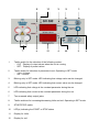
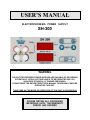
USER’S MANUAL
ELECTROPHORESIS POWER SUPPLY
SH-300
WARNING
THE ELECTROPHORESIS POWER SUPPLIES ARE CAPABLE OF DELIVERING
POTENTIALLY LETHAL VOLTAGE AND IS TO BE OPERATED ONLY BY
QUALIFIED TECHNICALLY TRAINED PERSONNEL.
PLEASE READ THE ENTIRE OPERATOR'S MANUAL THOROUGHLY BEFORE
OPERATING THIS UNIT.
TAKE CARE AS THE MODE OF OPERATION OF THIS UNIT IS CONTINUOUS
PLEASE RETAIN ALL PACKAGING
MATERIALS UNTIL THE WARRANTY
PERIOD HAS EXPIRED
Description
Microprocessor controlled switching Power Supplies
.
The IBI-Shelton SCIENTIFIC power supplies are CE marked and
complies with the following requirements : EN 61326-1 – Edition 1997,
FCC part 15 Class B – Edition 1995 - EMC directive 89/336/CEE.
They are certified and manufactured according to the IEC 1010-1 standard
and test regulation.
.
These power supplies are equipped with an automatic restart system in
case of mains failure. When the power returns, an audible alarm sounds
for 10 seconds and the power automatically restarts with the previous set
values. If during the power failure the electrophoresis unit is disconnected
from the power supply, the alarm still sounds when the mains supply
returns. Because no load is connected the power supply it will immediately
shut-down and the output will be set to zero.
.
Direct reading of the programmed set values and actual values before
and during the cycle.
.
.
Volt and mA adjustable during a cycle.
Stabilisation and automatic crossover between the parameters
according to the set limitation values and when output limits are reached. 2
Red LED(s) indicate the constant mode.
.
.
.
2 operating modes: constant voltage - constant current.
Settings by tactile switches on moisture resistant membrane panel.
Battery-backed memory feature "saves" last output set values in the
event of a power failure or when the run is terminated and the unit is
turned off.
.
.
2 red LED(s) display settings for output voltage and current.
2 recessed safety output jacks allow simultaneous operation of 2
electrophoresis units.
.
Fault detection and 500µA current leakage detection, or no load
automatically shuts down output and indicates the fault by the “STOP”
LED blinking and an audible alarm.
Safety precautions
THESE POWER SUPPLIES ARE CAPABLE OF DELIVERING POTENTIALLY
DANGEROUS VOLTAGE AND ARE TO BE OPERATED ONLY BY QUALIFIED
TECHNICALLY TRAINED PERSONNEL. PLEASE READ THE ENTIRE
OPERATOR'S MANUAL THOROUGHLY BEFORE OPERATING THIS UNIT.
TAKE CARE AS THE MODE OF OPERATION OF THE UNIT IS CONTINUOUS
If the power supply is used in a manner not specified by IBI-Shelton
SCIENTIFIC, then the protection systems of the equipment may be impaired.
For additional information, please call the IBI-Shelton
distributor’s Technical Resources Department.
SCIENTIFIC
or your
Never attempt to remove the outer casing or make any repairs to the unit.
Contact IBI-Shelton SCIENTIFIC immediately if there is need for repair or a
servicing need should arise.
The unit must be grounded. Use only the line cord supplied with the
unit for safe operation. The use of a line cord other than this or one
supplied by IBI-Shelton SCIENTIFIC may result in user hazard.
For UK users, check the mains plug of the line cord to make sure it is
equipped with a protection fuse not exceeding 3 A. Connect the line cord
directly into a properly rated, 210/250VAC 50/60Hz or 105/125VAC
50/60Hz three pins wall outlet.
For connection between the power supply and the
electrophoresis equipment, use only safety output power
cords equipped with Black and Red recessed plugs.
Check the power cords and the black and red recessed safety jacks
periodically to make sure that they are in good condition. Do not use cords
which are cracked, nicked or in otherwise poor condition. Always make all
connections between the power supply and the electrophoresis equipment
prior to start-up of the output. Never place any objects other than high
voltage connectors rated to 1000V into the output jacks. Site the unit such
that the rear panel has at least 8” [20cm] of clearance to provide for
adequate unit ventilation.
The power supply must only be connected to electrophoresis equipment
manufactured with built-in safety protected male plugs.
It is also recommended to use electrophoresis equipment that can only be
connected when the protection lids are closed.
Specifications
Input supply voltage fluctuations not to exceed ± 10% of the normal voltage
Input supply, 110V model :
Input supply, 220V model :
Fuse value in the input plug:
Rated input power/current
Volt – Current range
Power
Mode of operation
Switching frequency
Output regulation stability
Minimum output
Value display accuracy
Input failure during the run:
Fault detection
Fault status
Earth leakage detection level
Output to earth impedance
Size
Weight
Environmental conditions
90 - 130V; 50 - 60Hz; 2A fuses
180 - 260V; 50 - 60Hz; 8A fuses
3A
400VAC
1 - 300V ; 1V step
1 - 400mA; 1mA step
0,6 - 120W
Continuous
23kHz
± 0,2% FS ± ½ digit
1V; 15µA; 0,6W
± 0,2 FS ± ½ digit
Audible alarm and automatic restart with
previously set values
Output supply stop, audible alarm
STOP LED blinking
Output to ground leakage
Output open circuit
Output short circuit
No regulation (Overheating, power circuit fault)
500µA
10Mõ min bypassed by 1nF max
24cm x 17cm x 11cm (DxWxH)
1,8kg
Indoor use,
Altitude up to 2000m
Temperature 10°C - 40°C
Maximum relative RH 80% for temperature up to 31°C decreasing linearly to 50%
RH at 40°C.
CLEANING
The power supply may be cleaned as required when the main
supply is isolated.
Cleaning should be carried out with a cloth moistened with
water or with tissues impregnated with 70% Isopropyl alcohol.
No other cleaning solutions should be used.
MAINTENANCE
There are no internal operator serviceable parts in this power
supply.
If the power supply should fail, the unit must be returned to the
authorized Service Center.
See troubleshooting guide for help.
SHIPMENT
When shipment or transport of the power supply is required,
use the packaging supplied with the unit. Store the unit in the
packaging, in a dry area.
Operation
Note: The last set output values are memorised.
A - Unit power up and immediat starting
1. Connect the AC line cord to a grounded, 3-prong wall outlet.
2. Connect the power supply to an electrophoresis device using the power cords
supplied with that unit.
3. To turn the power supply on, press the main power switch located on the rear
panel. The STOP LED (#10) illuminates, and the output display will read zeros.
4. To display and check last set values, depress SET/OUT switch (#1)
As soon as this switch is activated, the output display shows the last output set values
5. If the Volts and mA set values are correct, press START/STOP switch (#9) for
starting the run. The green LED (#10) illuminates.
6. The actual values are immediately displayed. According settings and gel
resistance, one of the constant mode LED(s) will be alighted :
(#5) for constant voltage – (#6) for constant current
7. When separation is terminated, press START/STOP (#9) to stop the run
8. Turn off the power supply by using the main power switch on the rear panel
B - Adjusting output set values when unit is on STOP mode
1. Depress the SET/OUT switch (#1)
As soon as this switch is activated, the output display shows the last
output set values
2. The Volts LED (#3) is blinking at first. Increase or decrease voltage by the
help of the two SET switches (#8)
3. Depress VOLTS/mA switch (#2) in order to select mA. The mA LED (#4) is now
blinking. Increase or decrease current by the help of the two SET switches (#8)
4. Press START/STOP switch (#9) for starting the run
5. The actual values are immediately displayed. According to the settings and
gel resistance, one of the constant mode LED(s) will be alighted:
(#5) for constant voltage - (#6) for constant current
6. When electrophoresis is terminated, press START/STOP switch (#9) to stop
the run
7. Turn off the power supply by using the main power switch located on the
rear panel
Maximum output values are as follows:
for 300V - maximum current 400 mA (120W)
for 400mA - maximum voltage 300V (120W)
C – Adjusting output set values when unit is on START mode
1. While the unit is running, depress the SET/OUT switch (#1).
As soon as this switch is activated, the output display shows the last
output set values.
2. The Volts LED (#3) is blinking at first. Increase or decrease the voltage by
the help of the two SET switches (#8).
3. Depress Volts/mA switch (#2) in order to select mA. The mA LED (#4) is now
blinking. Increase or decrease the current by the help of the two SET
switches (#8).
4. Press SET/OUT switch (#8) for displaying the new actual values
5. When electrophoresis is terminated, press START/STOP switch (#9) to stop
the run.
6. Turn off the power supply by using the main power switch located on the
rear panel
D – FURTHER INSTRUCTIONS
1. To view the set values during the run, depress the SET/OUT switch. The display
will show the set values as long as this switch is depressed. Once the SET/OUT
switch is released, the display will show the output values for three seconds, and
then switch back to displaying the actual output values.
2. It is possible to change the values during the run without depressing the
STOP switch.
3. To change the output set values during the run or in STOP mode :
• Depress the SET/OUT switch.
• Select the parameter by depressing the Volts/mA switch.
• The selected parameter is indicated by a corresponding blinking LED located
on the right of each display.
• Use the two SET switches until the appropriate output set value is reached.
• After 3 seconds, the new actual output values are automatically displayed
• To read immediately the new actual values, press SET/OUT switch.
4. In START status, when the SET/OUT switch is depressed, the Leds display the
output set values during three seconds and then switch back to displaying the
actual output values.
5. To establish the limiting (constant) mode for the particular experiment, set the
controlling parameter to the output desired, and increase the other output set
value until the appropriate mode LED (Constant Voltage or Constant Current)
illuminates. These LED(s) are located on the left of the displays.
6. If the non-controlling output set values is reached during the course of the run, the
power supply will automatically crossover to the new mode and control output
relative to that mode. The appropriate mode LED (Constant Voltage or Constant
Current) will illuminate.
7. If automatic crossover is desired during the run, adjust the output set value of the
second controlling parameter to the maximum setting desired. When actual output
relative to the second controlling parameter equals its output set value, the output
will cross over from the first controlling parameter to the second.
8. When the run has been completed, depress the STOP switch to cease power
output. Wait one minute before disconnecting the power cords from the gel unit.
9. Turn the main power switch off when the unit is not in use
User's protection and safety
An audible alarm and STOP LED indicate a fault situation and cut off the power
supply :
- Overload.
- Output to ground leakage
- Output open circuit
- Tank’s lead(s) disconnected or defective.
- Output short circuit.
Press STOP to resume and look for the wrong situation.
Press START to run again.
IMPORTANT
The power supply automatically restarts with respect to the set values when the
power is operating again after a power failure or repetitive micro failures during a
cycle. The STOP LED blinks for 10 seconds before operating again.
TROUBLESHOOTING GUIDE
CONDITION
PROBABLE CAUSE
REMEDY
Display fails to illuminate
when the POWER switch
is put on.
Fuses have blown
See Warning below
The desired MODE is not
flashing.
One of the other
parameters is
limiting output.
Increase the output set
value of the parameter
controlling output until
the desired output
mode is controlling.
Two different modes are
blinking alternatively.
Settings for both
parameters are too
close to the actual
output.
Increase the set value
for the mode you do not
wish to be limiting.
Settings switches are not
working.
SET mode is not operating
Depress SET switch
Audible alarm at power up
Automatic restart is coming
Press STOP to stop this function
The unit has been previously
cut off by the power switch when
running. Unit must always be
stopped by the STOP switch prior
to cut off by the power switch
Impossible to start the run,
Unit is coming back on STOP
mode with audible alarm
A fault situation avoid the
START mode to operate
See “user’s protection and
safety paragraph
WARNING
Never attempt to remove the outer casing or make any unit repairs.
Contact IBI-Shelton SCIENTIFIC if the need for repair or servicing should arise
Should the power supply fail, DO NOT remove the outer case of the unit and
attempt any repairs.
Contact IBI-Shelton SCIENTIFIC if the need for servicing the unit should arise.
7
5
11
3
2
1
6
12
4
10
9
1
Tactile switch for the selection of the following modes :
- OUT : Display of output values when the unit is running
- SET : Display of preset values
2
Tactile switch for selection of parameter to set. Operating in SET mode
- Volts : Voltage
- mA : Current
3
Blinking only in SET mode: LED indicating that voltage value can be changed
4
Blinking only in SET mode: LED indicating that current value can be changed
5
LED indicating that voltage is the constant parameter during the run
6
LED indicating that current is the constant parameter during the run
7
Two recessed safety output jacks
8
Tactile switches for increasing/decreasing Volts and mA. Operating in SET mode
9
START/STOP switch
10
LED(s) indicating the START or STOP status
11
Display for Volts
12
Display for mA
8