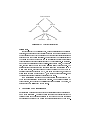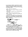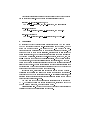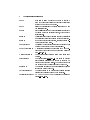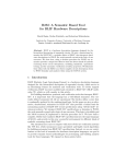
1
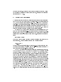
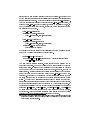
Capturing Requirements by Abstract State Machines:
The Light Control Case Study
Egon Borger
(Universita di Pisa, Dipartimento di Informatica, I-56125 Pisa, Italy
[email protected] { Visiting Microsoft Research, Redmond)
Elvinia Riccobene
(Universita di Catania, Dipartimento di Matematica e Informatica,
I-95125 Catania, Italy
[email protected])
Joachim Schmid
(Siemens AG, Corporate Technology,
D-81730 Munich, Germany
[email protected])
We show how to capture informally stated requirements by an ASM (Abstract State Machine) model. The model removes the inconsistencies, ambiguities and
incomplete parts in the informal description without adding details which belong to
the subsequent software design. Such models are formulated using application-domainoriented terminology and standard software engineering notation and bridge the gap
between the application-domain and the system design views of the underlying problem
in a reliable and practical way, avoiding any formal overhead. The basic model architecture reects the three main system parts, namely for the manual and automatic
light control and for handling failures and services. We rene the ground model into a
version that is executable by AsmGofer and can be used for high-level simulation, test
and debugging purposes.
Abstract:
1
Introduction
Despite intensive research in the area of requirements engineering there is no
agreement either on the process to follow or on the methods to use, for going
from an informally stated software engineering problem to a formulation which
can be integrated into the subsequent design process and therefore has to be
complete, consistent, abstract but rigorous enough to serve as faithful reference
for the design. We illustrate in this paper an approach to requirements capture,
which through analysis turns informally stated requirements into a rigorous requirements specication providing the possibility
{
to check by analytical means the internal consistency and the intrinsic completeness of the requirements, in terms of the rigorous specication,
{
to analytically and experimentally check the correctness and completeness of
the rigorous specication with respect to the informal requirements (faithfulness and adequacy),
{
to adapt the specication to requirement changes which occur during the
design,
{
to formulate an unambiguous \contract" between the application domain
expert, the \customer", and the system designer. This contract represents
for the customer the binding development goal and for the system designer a
reliable, i.e. clear, stable and complete, starting point for the implementation.
These properties demand that the requirements specication represents a
functionally complete but abstract description of suÆcient but not more than
necessary rigor which
1. can be read and understood by and justied to the customer as corresponding
to what he wants,
2. denes every system feature as far as this is semantically relevant for the
work the user expects the system to achieve (avoiding underspecication),
3. contains only what the logic of the problem requires for the system behavior (avoiding overspecication), i.e. does not rely upon any further design
decision belonging to the system implementation (like the representation of
objects, the serialization of parallel actions).
Such high-level specications of requirements { so-called ground models
[Borger 1999] { have to solve pragmatically the purely theoretically unsolvable
problem to link in a \justiably correct" way real-world problems to machine
models, i.e. vague largely natural language descriptions to formal code which is
governed by mathematical laws. They represent the authoritative formulation of
the requirements against which the implementation has to be checked and tested.
Using Abstract State Machines (ASMs), one can provide the needed conceptual,
experimental and mathematical justication for abstract models of given requirements. Indeed, on one hand, ASM models can be tailored to the (abstraction
level of the) application domain problem and thus be analysed and compared
to the real-world situation by direct inspection. On the other hand, the rigorous
nature of ASMs allows one to formulate conditions for system validation (test)
and verication (proof), for objective and repeatable machine or thought experiments (elaboration of test plans), together with internal consistency checks.
In this paper, we illustrate this technique by turning the requirements given
for the Light Control Problem [Light 1999b] into an ASM which constitutes an
executable ground model, a satisfactory starting point for the proper software
design.
1.1
The process of ground model construction
For building a ground model there are three things we have to do. The rst is to
collect the informally presented requirements information and to disambiguate
it, removing the unintended ambiguities and producing a suÆciently precise formulation (elicitation). The unambiguous description extracts from the informal
requirements the involved basic domains (types of objects), the appearing basic operations and the basic relations among the objects and the domains, in
a word the \object-oriented" structure of the system. This part of the resulting description is often called model signature (and indeed will constitute the
signature of the ASM we are going to develop for the Light Control Problem).
During the following design, the signature is typically transformed into data
structures, header and interface denitions. The semantic link of the relevant
high-level terms to the application domain notions and to the basic operation
sequences is typically documented in a lexicon or through use cases (user scenarios). Through checklists which relate informal to formal terms and vice versa, for
example by using hypertext links, one has a) to document that nothing has been
forgotten and b) to guarantee that the formalization is traceable. Through the
rather Socratic method of asking ignorant questions [Berry 1995] one can try to
make sure that the semantic interpretation of the informal problem description
is correctly captured in the mapping to the terms of the rigorous description.
The second thing to do is to structure the resulting description to make it
more transparent and more easely checked for internal consistency. Structuring prepares the description for change by parameterization and abstraction. It
also reveals similarities and commonalities among the requirements. During this
structuring work, it is crucial not to loose traceability to the informal requirements. This structuring work has also to make explicit the basic architectural
features which are implicitly imposed by a possible solution for the given problem
under the given constraints.
The third step is to complete the resulting description by exhibiting and
lling in, typically through additional requirements coming from the customer,
all the information which is missing in the informal problem description but
is necessary for a full problem statement. Typically this includes the analysis
of boundary conditions, of exception handling, of robustness features, etc. This
activity eventually turns the description into a ground model of the system
to be developed. This high-level model incorporates all the requirement (not
design) decisions which are relevant from the point of view of the application
domain (customer system view) and have to be documented explicitly during
the process of building the ground model. It helps checking and establishing the
completeness and correctness of ground models that ASM models are machines,
easy to understand for the practitioner, which can also be made executable so
that high-level features of the system to be developed { in particular scenarios
+
Informal Requirements
Application Domain Knowledge
dynamic functions
transition system
domains
external functions
Ground Model
manual
PROVER
mechanized
SIMULATOR
adding definitions
adding assumptions
Validation
TEST
CASES
Verification
stepwise
refinement
reflecting
design
decisions
using data from
application domain
Figure 1:
Code
Development Process
{ can be simulated and visualized by the customer.
This process of ground model construction is usually not linear, but iterative,
and typically is accompanied by extensive simulation, high-level proving activities, layout of test plans, etc. (see [Figure 1]). Nevertheless, it is important to
document not only the executable code but also the nal ground model { which
in the worst case will be completely dened through later changes which show
up only during implementation { to guarantee the traceability of the initial
requirements to the code and to enhance the maintainability and extendability of the resulting system. This implies in particular that during the design
process, the ground model is maintained and kept to correspond to the actual
design. Since ground models \are easier to read than the programs that they
describe"[Parnas 1999, p.195], they support the software developers' daily work
and improve its quality as advocated by Parnas.
1.2
Application to the Light Control Problem
The following sections illustrate for the Light Control Problem this requirements
engineering process by explicitly dening the signature, the structure, and the
complete list of additional requirement decisions which together result in the
construction of an ASM ground model for the Light Control Problem. We have
made this ASM executable using AsmGofer [Schmid 1999a], essentially by providing denitions of the features which remain abstract in the ground model, so
that the user can do experiments with the requirements (run user scenarios and
test suites).
We will concentrate our attention here on the ground model construction as
a method to disambiguate informally presented requirements, to structure them,
to analyse them (with respect to internal consistency and correctness) and to
complete them, from the customer's, not the designer's point of view, in a way
which makes them prototypically executable. As a consequence in this paper we
do not investigate the layout of test plans from the ground model, and we also do
not investigate any properties one might wish to be proved for the ground model.
Furthermore we do not adhere to any systematic documentation or traceability
practice, as is mandatory for industrial applications of the method. In particular,
we do not document here the iterative process of ground model construction
(which includes our reaction to the customer feedback [Light 1999a]), but only
its nal outcome.
We do however list explicitly all those additional requirements which we
introduce along the way in order to disambiguate the given informal requirements, to make them consistent and reasonably complete. This requirements
completion is a crucial part of capturing requirements and in practice has to
be worked out in close cooperation with the customer. The present problem
description [Light 1999b], despite repeated revisions due to customer feedback
[Light 1999a] reported in the introductory note, still contains numerous inconsistencies, incoherences and ambiguities which showed up during the ground model
construction. This fact is typical and shows the necessity to build requirements
ground models as a safe basis for software design. Here are some examples of
problems we identied in the informal requirements: missing priority requirements to avoid inconsistencies between actions involving \shared actors" (in
particular between manual and automatically triggered actions); the inconsistency of the informal requirements concerning the light scene upon reentering
a room; the ambiguity of notions like room occupation or uncontrollability of
hallway light; the incomplete denition of various basic concepts like switching
o lightgroups, pushing buttons, selecting ambient light scenes, etc. The complete list appears in the appendix and is explained in the following sections. If
our decisions for disambiguating the informal requirements do not always reect
the result of the customer feedback [Light 1999a], as one reviewer pointed out,
this is because our model has been built and made executable for the Dagstuhl
meeting [Borger et al. 1999a], long before that customer feedback became available. The interested reader is invited to experiment with adapting our model to
dierent decisions, to experience how naturally ASM models can be extended
or otherwise modied. For this very same reason of \design for change" we also
pay attention to build our model in a parametric way, exploiting the abstraction
features oered by ASMs.
2
Notation and Prerequisites
We use olny standard notation and therefore invite the reader to skip this section
and to come back to it only should the necessity arise. Our notation includes
ASMs, which represent a semantically well-dened, precise form of widely used
pseudo-code over abstract structures. We provide in the rest of this section some
intuitive explanations which should suÆce to correctly understand and use ASMs
for turning informally stated requirements into a rigorous form. We refer the
reader to [Gurevich 1995] for a detailed mathematical denition.
The states of ASMs are arbitrary structures in the standard sense they are
used in mathematical sciences, i.e. domains of objects with functions and predicates dened on them. The basic operations of ASMs are guarded destructive
assignments of values to functions at given arguments, expressed in the following
form:
if
cond
then
Updates
where cond is an arbitrary condition (boolean expression) formulated in the
given signature, Updates consists of nitely many function updates:
f (t1 ; : : : ; tn ) := t
which are executed simultaneously. The terms t1 ; : : : ; tn are arguments at which
the value of the arbitrary function f is set to t . For technical convenience we
treat predicates as boolean-valued functions.
An ASM M is a nite set of rules for such guarded multiple function updates.
The computation of an ASM is dened in the standard way transition system
runs are dened. Applying one step of M to a state A produces as next state
another state A , of the same signature, obtained as follows: First evaluate in A,
using the standard interpretation of classical logic, all the guards of all the rules
of M. Then compute in A, for each of the rules of M whose guard evaluates to
true, all the arguments and all the values appearing in the updates of this rule.
Finally replace, simultaneously for each rule and for all the locations in question,
the previous A-function value by the newly computed value if no two required
updates contradict each other. The state A thus obtained diers from A by the
new values for those functions at those arguments where the values are updated
by a rule of M which could re in A. The eect of an ASM M, started in an
arbitrary state A, is to repeatedly apply one step of M as long as an M-rule can
re. Such a machine terminates only if no rule is applicable any more (and if
0
0
the monitored functions do not change in the state where the guards of all the
M-rules are false).
We freely use standard notational extensions like case of, let and where. We
also use the additional ASM rule construct forall x with P do R with the intended
meaning that rule R is executed simultaneously for all values of x which satisfy
the property P . We also use macros, parameterized ASMs and a natural concept
of submachines which are dened more precisely in [Borger and Schmid 2000].
In addition we make use of the ASM function classication which we are going
to explain below.
It turned out to be practically useful to distinguish, in an ASM M , basic functions from derived functions (which are dened in terms of basic ones). Many
requirements can be formalized in this way, by reducing them through denitions to basic terms. This simple technique, long established in mathematical
sciences, provides a powerful high-level modularization and information hiding
mechanism.
Within derived or basic functions, static functions, which remain constant
during M -computations, are distinguished from dynamic ones, which may change
from M -state to M -state. Many application domain features showing up in requirements are of a static nature and can be described independently of the dynamics of the system to be built. This separation of concerns helps enormously
to keep high-level models of requirements small and transparent, graspable by
the human reader, avoiding the rightly criticised [Parnas 1999] size explosion
coming with most formalization methods in the literature.
Adapting the terminology introduced in Parnas' Four Variable Model
[Parnas and Madey 1995] we distinguish among the dynamic functions the controlled ones from the monitored ones which we also call in functions. The controlled functions are subject to change by an update appearing in a rule of
M . The monitored functions can change only due to the environment or, more
generally, due to actions of other agents. Controlled functions can be read and
written by M , they are functions f of M -updates f (t1 ; : : : ; tn ) := t and are
allowed to appear also in the arguments and values ti ; t . The in-functions typically serve to read system input (dynamic interface event). The way they are
updated depends on the specic system. The natural pendant to in functions
are out-functions which can only be written by M , i.e., appear only as f in M updates f (t1 ; : : : ; tn ) := t but nowhere else, in particular not in ti ; t and not in
rule guards. Last but not least, there are shared functions which can be written and read by M and by some other agent and for whose consistency usually
a protocol has to be devised. Shared functions help to naturally reect multiagent computations and combined read and write use of locations, like ports
in chip design which are used for both input and output. This classication is
pictorially represented in [Figure 2] and extends the classication appearing in
function/relation
basic
static
derived
dynamic
in
controlled
Figure 2:
shared
static
out
ASM Function Classication
[Borger 1999].
For the case study to be discussed here, we use a particular form of monitored
functions, namely events which typically appear in the guards of rules and for
which it is assumed that they are consumed by ring the rule (read: their value is
reset to undef when the rule is applied). For the case study we deliberately leave
the details of the event model open and limit ourselves to specify as contraints
those conditions which are explicitly imposed by the requirements. In the following we need in particular the case of boolean-valued events which, by becoming
true, enable a rule to be red and become instantly false by ring the rule. The
special feature of events is that if e enables at clock time (computation time ) t
a rule which is red, its being consumed does not exclude that e may have an
enabling value again at clock time t + 1, namely in the case when, between the
system's computation moments t and t +1, the event happens once again. These
two instances represent dierent occurrences of the event.
For modularization purposes we use parameterized submachines in a way
which supports established programming practice. For a precise denition of
these concepts, in the context of parallel execution of multiple ASM rules, we
refer the reader to [Borger and Schmid 2000].
3
Capturing the Requirements
In this section we analyse the given Light Control requirements and express them
in a mathematical form. We introduce formal pendants (the signature) for the
various objects and operations mentioned in the document and use denitions
and algorithmic notation (ASM rules) to express their static and dynamic de-
pendencies. To facilitate checking the correctness and the completeness of our
modeling, we largely follow the order in which the requirements are presented in
[Light 1999b]. This implies that we develop the model in a bottom up manner,
although for a better understanding of the resulting entire model, a top down
reading will be helpful.
After the short introduction, [Light 1999b] begins with the oor description
(Part 2) to dene the signature of the system to be developed, i.e. a listing of
its components with the associated data structures. We reect this signature
denition by listing and classifying the basic classes of system objects and their
properties. In Part 3, [Light 1999b] distinguishes three categories of informal
needs, the user needs, the facility manager needs, and fault tolerance. We obtain
a modularization of the requirements by parameterizing and grouping the user
and the facility manager needs into the requirements for the possible manual
interactions of the user or facility manager with the control system, such as
pressing buttons (reecting essentially Section 3.1 of [Light 1999b]), and into the
automatic actions which are triggered by the control system, such as switching
o light in unoccupied rooms. At the end we describe the malfunctions (reecting
Section 3.2 of [Light 1999b]).
This is already a good place to introduce the formal representation of a
distinction which is made in [Light 1999b] for each category of needs, namely
between actions which are triggered by the user or the facility manager and
actions which are triggered by the control system (due to some calculation on
the basis of external information). We express this distinction by a dynamic
controlled function mode which indicates whether the current light setting operation in a room has been done manually, by the user or the facility manager,
or automatically. In an object-oriented perspective this function can be thought
of as being parameterized by rooms.
3.1
Basic objects and operations (Signature)
The basic objects appearing in the oor description are rooms and hallways,
more precisely hallway sections. They are associated with light groups (window
and wall ceiling lights for rooms and ceiling lights for hallways) which come
with operations of pushing various buttons (on the wall or a control panel)
and of actuating dimmers. Rooms and hallways are also associated with various
motion detectors, light sensors, and door closing contacts. There are also status
lines which report status values of the associated light groups.
The staircases, which are mentioned in the Floor Description, enter the problem really only through their motion detector. To avoid the proliferation of irrelevant object types we include these staircase motion detectors in the class of
motion detectors which are related to the doors for entering a hallway from a
staircase.
These objects enter our formalization as parameters of the various actions
which are described in the following sections. In a systematic documentation of
the requirements elicitation one has to list explicitly the complete signature; the
basic objects have to be dened through the lexicon, their properties as well
as the conditions imposed on the operations have to be listed systematically,
making sure that the list is complete and correct with respect to the application
domain information which underlies [Light 1999b]. We abstain from doing this
here; any reliable, systematic method can serve this purpose.
3.2
User interactions (Manual light control)
[Light 1999b] states in Section 2.1-2.4, Paragraphs 7-11 that every room has two
wall switches, one for the wall ceiling light group and the other for the window
ceiling light group. The behavior, if the corresponding push button is pushed, is
formulated in Section 2.1.2 as follows.
1. If the ceiling light group is completely on, it will be switched o.
2. Otherwise it will be switched on completely.
We capture this requirement with the rule Room wall button . This rule is parameterized over a room and a light group. The fact that pressing the button is
an external event over which the system has no control is reected by an event
function lightgroup wall button pressed which is supposed to become true when
the corresponding button has been pressed and to become false when the rule
res whose guard contains the event function (PushButtonReq)1 . This interpretation resolves the incompleteness of the denition for push button in the
dictionary where it is not made clear when the light eect should take place, at
the beginning or at the end of the possibly prolonged button pushing action.
Room wall button (room; lightgroup) =
if lightgroup wall button pressed (room; lightgroup) then
if lightgroup is completely on (room; lightgroup) then
Switch lightgroup o (room; lightgroup)
else
Switch lightgroup completely on (room; lightgroup)
Notation: We use italic font for rules and functions. Rule names always start
with an initial capital letter and function names with a lower case letter. Local
variables are denoted in roman font and we use typewriter for constants.
[1] Such additional requirements are provided for the purpose of a systematic documentation of all the decisions taken to interpret or extend the requirements in
[Light 1999b].
Switching a light group o and switching it completely on is dened as setting
all lights in the corresponding room to minDimValue or maxDimValue respectively
2 . This denition resolves the apparent contradiction in U1, considering it as safe
to allow a person who wants to rest in a room to choose a light scene in which
all the lights are switched o and the room is dark (U1Req).
As explained above, mode determines for each room whether the light was
set by the user (Manual) or by the control system (Ambient)3 .
Switch lightgroup o (room; lightgroup) =
mode (room) := Manual
forall light 2 lights in group (room; lightgroup)
Switch light (room; light; minDimValue)
Switch lightgroup completely on (room; lightgroup) =
mode (room) := Manual
forall light 2 lights in group (room; lightgroup)
Switch light (room; light; maxDimValue)
Following Section 2.6, in every hallway section there are switch buttons, linked
in parallel (see 2.6.3). The light in the hallway section has to be on if one button
is defective (any hallway button defect ). This is according to NF5 where we
interpret \not controllable manually" in view of the safety requirement U1, as
meaning that at least one hallway button is defective (NF5aReq). It would be easy
in our ASM model to change this to a \local" interpretation of \not controllable
manually" in NF5 by parameterizing any hallway button defective by buttons
as arguments. The event function hallway button pressed indicates that a switch
button has been pressed and becomes false by ring the rules in which the event
appears in the guard.
Hallway button (hallway) =
if hallway button pressed (hallway) ^
:any hallway button defect (hallway) then
if light is on (hallway) then
Switch lights o (hallway)
else
Switch lights on (hallway)
According to the dictionary denition of \push button", switching light on or
o manually in rooms and hallways is similar. We reect this uniformity by
[2] Following good system development practice we use symbolic names rather than
constants, like 0% and 100%.
[3] This interpretation of Ambient does not preclude to let the light from the sun be
part of what is understood by the environmental light.
introducing the term location standing for rooms and hallways. Switching on or
o for a location is dened as setting all lights of the location to minDimValue or
maxDimValue respectively. We group these lights for short as lights at (location ).
Although for uniformity reasons we formulate Switch lights on for locations, we
will use Switch lights on only for hallways, because by requirement U5,U6,U9
and the dictionary entry \light scene", the light in a room is switched on only
for a lightgroup as a whole.
Switch lights on (location) =
forall light 2 lights at (location)
Switch light (location; light; maxDimValue)
Switch lights o (location) =
forall light 2 lights at (location)
Switch light (location; light; minDimValue)
if location is room (location) then
mode (location) := Manual
The facility manager can switch o the ceiling light in a room or hallway section
if the room or hallway section is not occupied (FM6).
Manually switch o (location) =
if manually switch o pressed (location) ^ :occupied (location) then
Switch lights o (location)
The rule uses the function occupied . [Light 1999b] does not describe how to
determine occupation. Rooms and hallways have motion sensors but these can
sense only motion. Imagine somebody is sitting for a while quietly on his chair
in a room so that the motion sensor reports no motion. However, the room is
still occupied. Therefore a reasonable denition for a location to be not occupied
is that there has been no motion for a period of max quiet time (RoomOccupationReq). It remains to be determined whether this function is xed once and
for all or whether it can be changed and what is its concrete value for a given
system.4 To reect the malfunction requirement NF4 we include the case that a
location is occupied if at least one of its motion detectors does not work correctly,
so that in this case the light cannot be switched o by the facility manager. To
guarantee the consistency between user and facility manager light updates in the
rules Room wall button , Hallway button , Manually switch o , Control panel
we assume that the motion sensor detects when users push buttons (MotionDetectorReq). This is a semantic constraint which relates the notion of being
occupied to the event functions pressed associated to buttons.
[4] Dan Berry remarked correctly that this denition does not take into account the case
of somebody taking a nap who would not like to be disturbed by the light coming
back due to moves in the sleep.
occupied (location) =
current time last motion (location) max quiet time
The dynamic function last motion stores the time of the last motion and we
update the function by observing the motion detector. The monitored function
somebody is moving yields the value of its location's motion detector. To satisfy
NF5, we assume that the function somebody is moving is true if the corresponding motion detector is defect (NF5bReq).
Observe motion detector (location) =
if somebody is moving (location) then
last motion (location) := current time
There is one more action which is triggered by user interaction. According to
U5,U6,U9, one can use the control panel to control the ceiling lights and the
light scene. The ceiling lights can be switched on and o. Before collecting the
requirements for the light scene we rst analyse the overall functionality of the
control panel. We use an additional event function switch value to express the
on or o position chosen by the user for the switch in question.
Control panel (room; switch) =
if switch pressed (room; switch) then case switch
AmbientSelection !
of
Activate light scene (room; last light scene (room))
LightGroup(lg) !
switch value (room; switch) of
On ! Switch lightgroup completely on (room; lg)
Off ! Switch lightgroup o (room; lg)
case
SceneSelection !
case
switch value (room; switch) of
Scene(s) ! Set light scene (room; s)
One has to guarantee that simultaneous pushing on wall buttons and on the
control panel does not produce eects which exclude each other. One can for
example assume that the hardware solves this conict, or one could establish a
xed priority (PushButtonReq).
The preceding denition fullls the informal needs U5, U6, and U9. The button AmbientSelection activates the light scene which was set by the action
SceneSelection using the control panel.
Set light scene (room; scene) =
if mode (room) = Ambient then
Activate light scene (room; scene)
else
last light scene (room) := scene
The rule Set light scene for scene selection in ambient mode changes the current
activated light scene and in manual mode simply stores the selected value in the
dynamic function last light scene . In the second case the scene can be activated
by pressing AmbientSelection.
A light scene contains an ambient light level and an ordered list of lights
together with a dim value for each light (see Requirement 2.10, Paragraph 19).
As the dictionary indicates under the entry light scene, the control system has
to switch on the lights in the given order with the corresponding dim value
in order to achieve the specied ambient light level. Reecting FM1 the control
system must also take into account the ambient light from outside. We capture
these requirements by introducing a function lights to turn on which computes
an ordered set containing all lights that should be switched on in this order
together with their dim values (LightSceneReq). Introducing an order makes the
dictionary denition of \light scene" uniform with respect to the way light scenes
and their light groups are built from components, achieving easy adaptability to
changing requirements. The function depends for each room on the value of the
outdoor light sensor and of the activated light scene. This specication leaves
still much freedom for detailing the structure of light scenes. The fact that we use
this function only for rooms and not for hallways reects that the requirements
FM1 and NF3 are useless for hallways if they have no windows, as is suggested by
Figure 1 in Paragraph 5 of [Light 1999b] (HallwayReq)5 . Note that the derived
function lights to turn on (see below) takes into account the information about
malfunctioning lights.
Activate light scene (room; scene) =
mode (room) := Ambient
last light scene (room) := scene
if
scene = default light scene (room) ^
outdoor light sensor defect (room) then
Switch lights on (room)
else
let lights on = lights
forall (light; value)
to turn on (room; outdoor sensor (room); scene)
2 lights on
Switch light (room; light; value)
light 2 lights at (room) n fl j (l; v) 2 lights on g
Switch light (room; light; minDimValue)
forall
This rule also correctly reects the requirement NF2:
[5] FM1 and NF3 are useful however if, as one reviewer remarked, light should be taken into
account which may reach hallways through open doors of rooms. It is straightforward
to adapt our model to take also such an interpretation of the requirements into
account.
If any outdoor light sensor does not work correctly, the default light
scene for all rooms is that both ceiling light groups are on.
Also the part of NF1 which complements NF2 is reected by the assumption
that the value of outdoor sensor (room) remains constant if the sensor does not
work correctly (OutdoorSensorReq). This assumption reects that NF1 is not a
requirement on the controller, but on the way the sensor values are transmitted
as input to the controller.
Anticipating the rule Use daylight below we point out already here that the
denition of Activate light scene contains a decision about the interpretation
of requirement U10. Since nothing is said about what it means to maintain the
ceiling light group on a given light scene, we interpret this as requesting that the
ceiling lights are set to minDimValue if they do not enter explicitly the lights to
be turned on for the given light scene (U10Req).
The control panel also allows to set the value T1 for a room (U7). This
is formalizable by updates of a corresponding function t1 { similarly for FM4,
FM5. We group them into the Set parameters part of the Failure and service
submachine.
3.3
Automatic light control
The automatic control system is required to be able to switch on and o any
light in a room or in a hallway section. Switching on is used to ensure that there
is safe illumination in the room or hallway (U1, U13, U14). The lights in the
hallway sections are not dimmable so that switching on can be done there only
completely. Switching on is triggered by the two events (i) motion in the hallway
(somebody is moving ) and (ii) a door is open (some door is open ).
Auto switch on in hallway (hallway) =
if (somebody is moving (hallway) _ some door is open (hallway)) ^
light is o (hallway)
then
Switch lights on (hallway)
Switching on the light in a room is more complicated. According to U3 and U4
one has to distinguish two cases:
U3 If the room is reoccupied within T1 minutes after the last person has left the
room, the chosen light scene has to be reestablished.
U4 If the room is reoccupied after more than T1 minutes since the last person
has left the room, the default light scene has to be established.
In the rst case, instead of establishing the chosen light scene we use the last
light scene (U3Req) since otherwise the requirements would be incoherent, as
the following example shows. By the denition in the dictionary in Part 4 of
[Light 1999b], the chosen light scene is the scene selected with the control panel.
Imagine the following scenario:
1. Person A enters the room and selects scene s .
2. Person A leaves the room for more than T1 minutes and no other person
enters the room.
3. Person B enters the room. According to U4, the default light scene should
be established.
4. Person B does not change the light scene and leaves the room.
5. Person B enters within T1 minutes. According to U3, we should establish
the chosen light scene s .
As one can see Person B , upon entering the room for the rst time, gets the
default light scene and, upon reentering, gets the chosen light scene of Person
A. This seems to be a aw in [Light 1999b] and we therefore select the last light
scene. For the reasons explained above we abstract from the value T1 and use
the function recently occupied .
Auto switch on in room (room) =
if (somebody is moving (room) _ some door is open (room)) ^
light is o (room)
then
Activate light scene (room; scene)
where scene = if recently occupied (room) then
last light scene (room)
else default light scene (room)
recently occupied (room) = current time
last motion (room) t1(room)
We do not commit here to any particular denition of default light scene (DefaultLightSceneReq). The denition in the dictionary is probably not reasonable
because with that denition, requirement U4 makes no sense.
The control system switches o the light in a room or in a hallway section
if the location is not occupied for T3 or T2 minutes respectively (FM2, FM3).
In accordance with requirement NF5 we do not switch o the light in a hallway
section if one of its buttons is defective. To reect the malfunction condition NF4,
we stipulate that occurrence of a malfunction for a motion sensor is interpreted
as presence of motion so that the location appears as occupied.
Auto switch o (location) =
if location is hallway (location) ^ any hallway button defect (location)
then skip
else
if
:occupied (location) ^ no motion for long time (location) ^
:some door is open (location) ^ :light is o (location)
then
Switch lights o (location)
no motion for long time (location) =
if location is room (location) then
current time last motion (location) > t3 (location)
else
current time
last motion (location) > t2 (location)
The control system should use daylight to achieve the desired ambient light level
(FM1). We model this by reactivating the current light scene if the room is in
ambient mode and there is no request for the ceiling lights. The following rule
also reects the informal need U10.
Use daylight (room) =
if no event for ceiling light (room) ^ mode (room) = Ambient
Activate light scene (room; last light scene (room))
then
U2 is fullled automatically in our requirements model because an ASM state
remains unchanged unless a specic (user or control system) action triggers a
change for the value of some specied functions for some specied arguments.
3.4
Failure and service
The last part of [Light 1999b] is about malfunctions. There are two actions to
describe, namely identifying and handling malfunctions. Identifying malfunctions is a rather diÆcult application domain and not so much a software design
problem. [Light 1999b] does not provide any further details on this issue so that
we assume having a function malfunction occurs telling whether a component
works correctly or not; a component may be a hallway button, a light sensor, a
motion sensor or any light. For building a concrete plant with its control software, this function has to be further specied by the customer, together with
the support requested in FM8 for nding the reasons for occuring malfunctions.
To reect the malfunction requirement FM1 we stipulate that this function can
also be updated manually.
Malfunction =
2
forall component all components
if malfunction occurs (component) then
Handle malfunction (component)
According to U8, FM7, and FM10, the handling of malfunction logs the corresponding information. In the case in which a hallway button is defective we switch on
the lights in that hallway (NF5). In case a hallway motion detector is defective, by
assumption (NF5bReq) the function somebody is moving is true and we therefore switch on the lights by rule Auto switch on in hallway . In the following
rule we use i as index which has to match the name of the corresponding device
(sensor, button)
Handle malfunction (component) =
case
component
of
OutdoorLightSensor(i) !
room 2 rooms under lightsensor (i)
Inform user (room; LightSensorDefect(i))
Inform facility manager (LightSensorDefect(i))
Write log in database (LightSensorDefect(i))
forall
MotionSensor(location; i) !
location is room (location) then
Inform user (location; MotionSensorDefect(location; i))
Inform facility manager (MotionSensorDefect(location; i))
Write log in database (MotionSensorDefect(location; i))
if
HallwayButton(hallway; i) !
Switch lights on (hallway)
Inform facility manager (HallwayButtonDefect(hallway; i))
Write log in database (HallwayButtonDefect(hallway; i))
Luminaire(location; light) !
Inform facility manager (LightDefect(location; light))
Write log in database (LightDefect(location; light))
To satisfy requirement NF9 we add a rule
Detect unreasonable input
Since [Light 1999b] contains no information on the meaning of NF9, we leave it
to further renement steps to provide a detailed denition, resulting from the
discussion with the application domain expert who is supposed to know what
inputs have to be considered as \unreasonable".
The system should provide reports on energy consumption (FM9). We formalize this requirement by introducing a dynamic function dim value storing the
current dim value of a light. Switching the light is dened as setting a dim value.
If the dim value is less than 10% of the maximum dim value, then the light is
switched o (see [Light 1999b], Table 2):
Switch light (location; light; value) =
if
value < maxDimValue=10 then
status of light (location; light) := Light Off
else
status of light (location; light) := Light On
dim value (location; light) := value
Based on the values in dim value , we can dene the function power consumption
computing the current power consumption. The function has to take into account
the malfunctioning of lights:
P
power consumption = [p (l; dim value (l)) j l 2 dom (dim value )]
where p (l; v) = case light defect (l) of
NotDefect ! c v
DefectOn ! c maxDimValue
DefectOff ! c minDimValue
We use the constant c to adjust the dim value to the electrical power. The energy
consumption is the integral of the power consumption over the time. Therefore
we store the power consumption in each step in a dynamic function and dene
the energy consumption as the product of the interval te with the sum of the
power consumptions. We assume that the following rule will be executed every
te minutes.
Report energy consumption =
consumption (current time )
:= power consumption
energy consumption (current time ) := te consumption (t )
P
t
3.5
The requirements ground model
The model which results from the formalization in the preceding subsections is
the following ASM, consisting of three submachines:
Light = Manual light control
Automatic light control
Failure and service
The Manual light control actions were described in [Section 3.2]. We introduced
rules for switching light on and o in hallways and in rooms and described the
functionality of the control panel.
Manual light control =
forall location 2 all locations
Manually switch o (location)
if location is room (location) then
Room wall button (location; LightGroupWall)
Room wall button (location; LightGroupWindow)
Control panel (location; switch(location))
if :location is room (location) then
Hallway button (location)
The second machine Automatic light control consists of automatically switching
light on and o and using daylight to achieve the desired light level. Due to
automatically switching lights on and o, we have also to observe the motion
detectors. The rules are described in [Section 3.3].
Automatic light control =
forall location 2 all locations
Auto switch o (location)
Observe motion detector (location)
if location is room (location) then
Auto switch on in room (location)
Use daylight (location)
if :location is room (location) then
Auto switch on in hallway (location)
The last of the three submachines is Failure and service , containing handling
of malfunctions, detecting unreasonable inputs, reporting energy consumption,
and setting parameters (reecting FM4, FM5, FM11, U7).
Failure and service =
Malfunction
Detect unreasonable input
Report energy consumption
Set parameters
One can use dierent policies for the synchronization of the three machines of
Light which has to guarantee the consistency of the three machines' update
actions in the shared data area. One possibility is to make specic priority or
scheduling assumptions on possibly conicting actions, as we have indicated at
various places during the formalization of the requirements. Another possibility
is to impose a concrete scheduling on the coordination of the three submachines.
Such a global policy relegates the consistency problem to the local levels of
the single submachines. For our ground model, we can assume, for example for
its executable version explained in the next section, that the manual and the
automatic submachines alternate at a xed rate { fast enough to guarantee the
desired reaction time of the light system to user or environment input { and
that the failure and service submachine is executed in between with a certain
predescribed frequency, again determined by the time requirements for failure
handling and general services. [Light 1999b] leaves all these issues completely
open. In the ground model we could have reected this freedom explicitly by
introducing appropriate choice functions which determine at which time which
submachine is running. For the executable version of our ground model we had
to make some concrete realistic decisions.
We assume starting at an initial state in which all rooms and all hallways are
empty and all lights are o. Especially, we assume the following initial values for
our dynamic functions:
mode (room)
= Manual
last light scene (room) = default light scene (room)
last motion (location) = 0
4
Ground model validation
In this section we provide further details for the macros used in the previous
sections which allow us to turn the ground model into an executable model
which has been implemented in AsmGofer and is available electronically (see
[Schmid 1999b]). This executable ground model version allows the customer to
validate [Light 1999b] by experiments with our model. A preliminary version
of this simulation model was presented in a demo at the Dagstuhl seminar on
Requirements Capture [Borger et al. 1999b]. The denitions presented in this
section have to be added to the requirements which occur in [Light 1999b] and
can be viewed as further decisions made for directing the real (not any more
prototypical) design. We skip the standard data structures needed to encode
locations, lights, light groups, actuators, light sensor, etc.
Inform user (room; malfunction) =
user information (room; current time ; malfunction) := True
Inform facility manager (malfunction) =
facility manager (malfunction; current time ) := True
Write log in database (malfunction) =
database (current time ; malfunction) := True
Typically the physical realization of Inform user will be required to appear on
the control panel display, but other solutions are possible.
There are several derived functions which can easily be dened and are needed
for an executable version. Some of these denitions are listed below:
lightgroup is completely on (room; lg) =
8 l 2 lights in group (room; lg) : dim value (room; l) = maxDimValue
light is on (hallway) =
8 l 2 lights at (hallway) : status of light (hallway; l) = Light On
light is o (location) =
8 l 2 lights at (location) : status of light (location; l) = Light Off
5
Conclusion
By capturing the Light Control Problem requirements as an ASM and making
the ASM executable to support high-level simulation and debugging, we have
shown how a piece of theory { the concept of ASM { can be used with practical advantage in a sensitive part of the software development process. The
reader may wish to check that in elicitating, specifying and implementing the
informal requirements, we have reected all the requirements which are listed in
the Problem Description, including the real-time aspects, except U11, U12, and
NF6-8 which are about norms and installation issues. We have disambiguated
the requirements, removing inconsistencies and incoherencies, and have completed them through additional conditions which for documentation purposes are
listed in the appendix. The semantic relevance of these additional requirements
is dierent from that of those additional denitions which we have provided as
renements of the ground model to make it executable.
In this case study, structuring elements appear only in the form of parameterization of denitions and rules which exhibit the uniformity of certain requirements and make the speciction reusable. In industrial applications, the
situation is rather dierent; architectural requirements usually occupy a large
place there [Hofmeister et al. 1999].
The AsmGofer code which implements our specication can be compiled to
C++. The entire modeling and implementation eort, including most of the
work to write up this paper, was half a person month.
Acknowledgement. We thank Dan Berry and three anonymous referees for
critical comments on an earlier version of this paper.
A
Additional requirements
U1Req
It is safe to allow a person who wants to rest in a
room to choose a light scene in which all the lights are
switched o and the room is dark.
U3Req
Instead of establishing the chosen light scene we use
the last light scene.
U10Req
If the ceiling lights do not enter explicitly the lights to
be turned on for the given light scene, they are set to
minDimValue.
NF5aReq
Ceiling lights in a hallway section are \not controllable
manually" if at least one hallway button is defective.
NF5bReq
If a motion detector is defective, its sensor value behaves as if there is motion.
PushButtonReq
Consistency of simultaneous pushing on dierent wall
buttons (xed priority or hardware solution).
RoomOccupationReq A reasonable denition for a location to be not occupied is that there has been no motion for a period of
max quiet time .
MotionDetectorReq
The motion sensor detects motion when users push
buttons.
LightSceneReq
The function lights to turn on computes an ordered
set containing all lights that should be switched on
together with their dim values. The order of the set is
the order in which the lights should be turned on.
HallwayReq
The requirements FM1 and NF3 are useless for hallways
if these are without windows.
OutdoorSensorReq
The sensor value of an outdoor light sensor remains
constant if the sensor does not work correctly.
DefaultLightSceneReq We do not commit to any particular denition of
default light scene .
References
[Berry 1995] Berry, D. M. (1995), "The importance of ignorance in requirements engineering", Journal of Systems and Software, 28(2):179{184.
[Borger 1999] Borger, E. (1999), "High level system design and analysis using Abstract
State Machines", In Hutter, D., Stephan, W., Traverso, P., and Ullmann, M., editors,
Current Trends in Applied Formal Methods (FM-Trends 98), number 1641 in Lecture
Notes in Computer Science, pages 1{43, Springer-Verlag.
[Borger et al. 1999a] Borger, E., Horger, B., Parnas, D., and Rombach, D. (1999),
"Requirements Capture, Documentation and Validation",
Web pages at:
http://www.iese.fhg.de/Dagstuhl/seminar99241.html.
[Borger et al. 1999b] Borger, E., Riccobene, E., and Schmid, J. (1999), "Software requirements specication of the Light Control System", In Borger, E., Horger, B.,
Parnas, D., and Rombach, D., editors, Requirements Capture, Documentation, and
Validation, Dagstuhl Seminar No. 99241.
[Borger and Schmid 2000] Borger, E. and Schmid, J. (2000), "Composition and submachine concepts", In Computer Science Logic (CSL 2000), Lecture Notes in Computer Science, to appear.
[Gurevich 1995] Gurevich, Y. (1995), "Evolving Algebras 1993: Lipari Guide", In
Borger, E., editor, Specication and Validation Methods, pages 9{36, Oxford University Press.
[Hofmeister et al. 1999] Hofmeister, C., Nord, R., and Soni, D. (1999), "Applied software architecture".
[Light 1999a] Light (1999), "Light Control { customer feedback", Web pages at:
http://rn.informatik.uni-kl.de/~recs/qna.
[Light 1999b] Light (1999), "Light Control { problem description", Web pages at:
http://rn.informatik.uni-kl.de/~recs/problem.
[Parnas 1999] Parnas, D. (1999), "Formal methods technology transfer will fail", Journal of Systems and Software, 40(3):195{198.
[Parnas and Madey 1995] Parnas, D. and Madey, J. (1995), "Functional documents
for computer systems", Science of Computer Programming, 25(1):41{61.
[Schmid 1999a] Schmid, J. (1999), "Executing ASM specications with AsmGofer",
Web pages at: http://www.tydo.de/AsmGofer.
[Schmid 1999b] Schmid, J. (1999), "The light control system", Web page at:
http://www.tydo.de/AsmGofer/light.