1
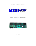
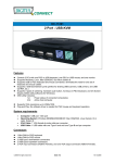
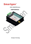
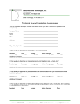
RAYMON ELECTRONICS, INC.
TLC-S9
User Manual
Revision July 2013
Table of Contents
Chapter 1 Preface………………………………………….………………………………………………………………1
1.1 Receiving and Inspection………………………………………………………………………………………1
1.2 Features………………………………………………………………………………………….………………1
Chapter 2 Connections and wiring…………………………………………..………………………………………2
2.1 Connections…………………………………………………………………………………………..…………2
2.2 Wiring Methods………………………………..………………………………………………………………..2
Chapter 3 Display and operation……………………………….……………………………………………………3
3.1Panel description………………………………………………………………………………………………..3
3.2.1 LCD…………………………………………………………………………………………………………….3
3.2.2 Memory card slot…………………………………………………….………………………………..……...3
3.2.3 Control buttons…………………………………………………………...……………………..……………4
3.2.4 Status LEDs………………………………….………………………………………………………………..4
Chapter 1 Preface
1.1 Receiving and Inspection
All Raymon TLC have gone through rigorous quality control tests at factory prior to ship. After receiving TLC-S9,
please check that the package includes :
-1pcs TLC-S9
-1User manual
-1pcs Software CD
1.2 Features
-There are 8 NO outputs to turning on or off electrical devices.
-12VDC/5A external power needed.
-DIN rail mount.
1
Chapter 2 Connections and wiring
2.1 Connections
In Figure 2.1, it briefly explains the connection of supply and loads.
Figure 2.1
Wiring Notes
Please observe the following wiring notes while performing wiring and touching any electrical
connections on the device.
- Ensure to check if the power supply and wiring of the "power" terminals is correct.
- Please use shielded twisted-pair cables for wiring to prevent voltage coupling and eliminate electrical noise and
interference.
2.2 Wiring Methods
Each TLC-S9 device has 8 NO output. These outputs can either directly connect to loads or in an special
situation trough contactor able to drive heavy loads.
In Figure 2.2, each connection has been explained.
Figure 2.2
2
Chapter 3 Display and operation
3.1Panel description
In Figure 3.1, each part of the panel has been explained.
Figure 3.1
LCD
Memory card slot
Status LEDs
Control buttons
3.2.1 LCD
It shows the proper information of each procedure. Normally shows Antenna and current network name.(Figure
3.2)
Figure 3.2
3.2.2 Memory card slot
This device can save received configuration in MMC/SD memory card, Including date, time and received
configuration string.
3
3.2.3 Control buttons
TLC device has three control buttons :
-MRST (Module Reset) :
In some situation its necessary to reset the device because of the error due local network problems.
-SRST (SIM card Reset) :
In some situation its necessary to reset the SIM card because of the error due local network problems.
-FRMT (Format memory card) :
This botton is used to format the memory card internally without another device like computer etc.
3.2.4 Status LEDs
To show the network and supply status, this device uses to LEDs :
-NETW :
It shows the status of local network. The working state of this LED is listed in the following table :
State
Module function
Off
64ms On/ 800ms Off
64ms On/ 3000ms Off
Module is not running
Module does not find the network
Module find the network
-POWR :
This LED shows the state of module, whether is On or Off.
4
Chapter 4 The software
4.1 Software description
Raysoft has a simple and user friendly structure. Each part of the software shown in Figure 4.1.
Figure 4.1
Press to send
defined situation
Press to retrieve
current status
Output status indicator
Define desire
output situation
Press to set the number
5
Inserted SIM card
number
Raymon Electronics CO., LTD. www.RS‐TRONICS.com S‐UM1‐S2/July 2013 – All Right Reserved