1
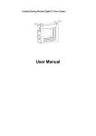
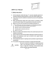
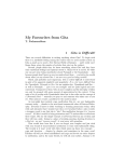
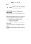
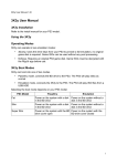
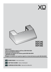
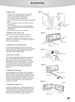
AH27 User Manual
Preface
CAUTION:
Please read this manual carefully, also with related
manual for the machinery before use the controller.
For installing and operating the controller properly and
safely, qualified personnel are required.
This product is designed for specified sewing machines and must not be
used for other purposes.
If you have any problem or any comment, please feel free to contact us.
Safety Instruction
1)
All the instruction marked with sign
must be absolutely observed or executed;
otherwise, personal injuries or risk to the machine might occur.
2)
This product should be installed and operated by persons with appropriate training only.
3)
Before connecting power supply cords to power sources, it’s necessary to make sure that
the power voltage is in the range indicated on the product name plate.
4)
Make sure to move your feet away from the pedals while power on.
5)
6)
Turn off the power and remove plug prior to the following operations:
■
Connecting or disconnecting any connectors on the control box;
■
Repairing or doing any mechanical adjustment;
■
Threading needle or raising the machine arm;
■
Machine is out of work.
Make sure to fasten all the fasteners firmly in the control boxes prior to the operation of the
system.
7)
Allow an interval of at least 30 seconds before repapering the system after power off.
Page1of16
8)
Repairs and maintenance work may be carried out by special trained electronic
technicians.
9)
All the replacement parts for repairing must be provided or approved by the manufacturer.
10)
The controller must be firmly connected to a properly grounded outlet.
Be sure to connect the controller to a properly grounded
CAUTION:
outlet. If the grounding connection is not secured, you
may run a high risk of receiving a serious electric shock,
and the controller may operate abnormally.
1、Product Introduction
1.1 Overview
These Series Digital AC Servo System consist of motor and controller which are separately
mounted on the same bracket, providing a very flexible mounting solution for customers. The
system can execute needle-down (or needle-up) position with external-synchronizer. And it can
be easily configured with different motors to match with various sewing machines, such as
lockstitch, dual-needle lockstitch, heavy duty, over lock stitch, interlock stitch and direct-driven
sewing machines. Employing a switch-mode power supply for the sensitive control circuitry, the
system can operate over a much wider voltage range. It has the following advantages installed
easy, large torque, small size, low-noise, high-efficiency, small shake and high-precision speed
control. Side-mount connectors make the connection more reliable and reduce the malfunction
caused by oil leakage.
1.2 Specification
Controller Type
AH27-55
AS27-70/-75
Max. Sewing Speed
(r/min)
5000
3500
Voltage Range
3000
AC (220±44 )V 50/60HZ
Output Power
550W
700W
750W
Max. Torque
3Nm
5.5Nm
6.8 Nm
0℃ ~ 40℃
Environment
The motor way of
Belt drive/
transmission
Direct drive
Belt drive
Page2of16
2. Installation Instructions
2.1 Motor Installation
Step 1: Mount lifting bracket. When motor installed under the machine table, as needed, to drill
holes in the following diagrams (see Fig. 2-1 the example for USA base table) for the
installation, mount lifting bracket.
Fig.2-1
Step 2: Install the motor (see Fig.2-2) and then tighten the lifting bracket.
Fig.2-2
2.2 Controller Installation
Fig.2-3
2.3 Controller shape dimension
Fig.2-4
Page3of16
3. Power Connection and Grounding
Ground wire (Green/yellow) must be grounded. Use the correct connector and
extension wire when connecting ground wire to Earth and secure it tightly (see Fig.3-1).
Control box cable
Yellow green line
Brown( AC220V)
Blue( neutral wrie)
Yellow green
( grouding wrie)
Brown( AC220V)
Yellow green
( grouding wrie)
Blue( neutral wrie)
Control box
Control box cable plug
Fig. 3-1
Ensure all power cord, signal wire and grounding wire not be
pressed by other matter or over-twisted ,and not be too close
CAUTION
to belt and belt wheel, keep 3cm-distance for safety.
A 1Ф/220V power from a 3Ф/380V Power source Connection (See Fig.3-2):
If the system have no Neutral point, then this servo motor is
CAUTION
not suitable for this connection.
Fig. 3-2
4. Definition of controller interface
Connections between control box and other accessories are illustrated in Fig.4-1.
Plug these connectors into the corresponding sockets in control box.
Page4of16
Fig. 4-1 controller link
AH27 Operation Panel (HMI) Instruction
1、Operation Panel (HMI) Instruction
1.1 Panel Instruction:
AH27 operation Panel is divided into(See Fig1-1)digital tube area and key operation area.
The digital tube area is positioned in the middle of the operation panel. It consists of 3 digital
tubes, used to display function setting and parameters. There are 2 keys at the top of the digital
tube area, they are "P” and" S". There are 3 keys at the bottom of the digital tube area and two
S
open or closed.
P
LED lights are located above the lower right two keys, showing the corresponding function are
LCD areas
Fig.1Panel Instruction
Page5of16
Table 1: Function of Key
No Appearance
Description
Function key:Combines with other keys to set a higher level of the parameter; the
password interface confirmation and other interface cancel function.
1
“P” key
pressed one time to return to the initial interaction in the parameter modification
interface, not to save the current parameters.
Save: Confirm the operating (except the password interface), the system saves the
2
current parameters in the parameter modification interface.
Hundred keys:Adjustable speed.Increase the highest bit. In the technician
3
parameter interface, it could increase the higher bit of the parameter. Combined with
the P key, it enters into the technician index interface.
Stop position key:Select up/down stop position. It is also used to increase the
4
middle bit of the digital value, each effective pressing once increase a numerical.
Soft start key: Select soft start function. It is also used to increase the lowest bit of
5
the digital value, each effective pressing once increase a numerical.
1.2 Digital interface instruction
Digital interface is divided with three state:The idle state, the indexing status and
data display state.
1.2.1 Idle state:When power on, it is the default display state.
Fig.1.2.1 idle state
1.2.2 The indexing status has three cases:
Fig.1.2.2 technician index
Fig.1.2.3 monitor index
Fig.1.2.4 error playback index
1.2.3 Data display state:
It shows diffident data according to the selected index - technician parameters, control
parameters and error code。
Fig.1.2.5 data display state
Page6of16
2、Shortcut set
In the idle state interface, it can be used to set the soft start and stop position function
directly.
2.1 Soft start set
In the idle state(Fig.1.2.1),press
(5 key), the soft start function will be toggle between
enable and disable. If enable the lamp above this key will be lightened(
will be off(
),otherwise the lamp
).
2.2 Stop position
In the idle state(Fig.1.2.1),press
lamp lightened (
(4key),toggle between up and down stop position. The
)shows that the needle will stop in the down position ,otherwise (
)the
needle will stopped in the up position.
3、Technical Mode
In the application, to make the controller works in a better condition or to satisfy our own
demand, we can adjust the technician parameters as the following steps.
Step 1: Under idle state, first press
(1key)and hold on,then press
(3key).Two keys
are pressed at the same time, digital tube display see figure 3.1, required to enter the password.
The default password is 000.
Fig.3.1 password interface
Step 2: Press
(3key)、
password, and then press
(4key)、
(5key),Modify the digital tube display to the correct
(1key ). If the password is correct, enter the parameters modified
index, see figure 3.2, or remain in the password input state, see figure 3.1.
Fig.3.2 technical index
Page7of16
Step 3:Under parameters index, press
(4key)、
(5key)to modify digital tube display
to the needs of the technology parameters. Technical parameters see table 1. Index number is
determined, press
(2key),enter to parameters of interface, see figure 3.3。
Fig.3.3 technical parameters
Step 4:Press
(3key)、
(4key)、
(5key)to modification of digital tube display to
the needs of the technology parameters.
Step 5:After parameter modified, press
(2key), confirm the parameter modification and
return to the index interface。If you don't want to save the changes by
the idle interface. Any time can press
(1 key), it will return to
(1 key) is returned to the free interface.
4、R&D parameter modification
First press
(1key)and hold on, then turn the power switch, you can enter the R & D
parameters; Other methods of operation with the technical parameters of operation.
5、Monitor mode
Step 1: Under idle state mode, first press
(1key)and hold on, press
(4key).Two keys
pressed at the same time, digital tube display see figure 4.1, monitor index interface.
Fig 4.1 monitor index
Step 2: Under parameters index, press
(4key)、
(5key)to modification of digital tube
display to the needs of monitoring index number . Monitor index see table 2. Index number is
determined, press
(2key),enter to monitor parameters of interface, see figure 4.2.
Page8of16
Fig 4.2 monitor parameters
Step 3:In the monitoring parameter interface, in addition to press
returns to the monitoring parameter index interface. Press
(1key) of any key,
(1key), returned to the idle state of
interface.
Step 4:Repeat step 2 for other monitoring parameters or step 3 exits to monitor mode.
6、Error playback
The controller could save the recent 8 error occurrence. Index 0 shows the most recent fault
code. Index 1 stores the error code occurred before index 0’s error. Fault code and fault relation,
see table 3.
Step 1: In idle state , first press
(1key)and hold on,then press
(5key),Two keys are
pressed at the same time, digital tube display see figure 5.1
Fig 5.1 error playback index
Step 2: Under error playback index, press
(4key)、 (5key)to modify digital tube display
to the needs of error playback index number(0-7). Error index number display correctly, press
(2key)entered the error recording interface, view the index number of the recorded fault code,
see figure 5.2.
Fig 5.2 fault code display
Step 3:In the failure code display interface, press any key except
playback index interface. Press
(1key), return to error
(1key) returned to the idle state of interface.
7、Automatic test
In the idle state interface,The first press
(1key) and
Page9of16
(2key)combination,then step on
the pedal controller immediately enter into the automatic test status. The controller will run
according to setting about test mode and test time operation, until the end of test.Press
(1key) and
(2key) combination again the controller will exit the test mode until the run
time exhausted.
8、Transmission ratio and the initial angle test
Under idle state,press
(1key) and
(3key)combination. You can enter the technical
parameter:
The initial angle test: P18 parameters adjusted to 2 (test the initial angle), the pedal is
pressed to start the test, the test after the parameter back to 0 to (normal operation mode).
Transmission ratio test: P18 parameter adjustment 3 (test drive), depressing the pedal to
start the test, the test after the parameter back to 0 (normal operation mode).
9、Operation note
To make the system running at peak performance, the customers for the first time using the
recommended test again the initial angle and transmission ratio. R & D parameters so as not to
be freely modified, and you incorrectly modify the normal use.
Table 1: Technician mode parameter:
Index
Default
Rang
0
20
10~80
Minimum sewing speed (display value*10)
1
350
20~700
Maximum sewing speed (display value*10)
2
2
1~9
3
13
10~80
No.
Comment
Soft start stitch number
Soft start maximum sewing speed (display value*10)
System accelerate sensitivity ( D i r e c t d r i v e transmission
Speed
4
13
1~20
can be set up to a large value;belt transmission don't set large
value or too much noise and vibration. This parameter do not
affect the electrical)
System decelerate sensitivity ( D i r e c t d r i v e transmission
can be set up to a large value ; belt transmission don't set
5
20
1~80
large value or too much noise and vibration. This parameter do
not affect the electrical )
Page10of16
6
80
20~120
Measurement of transmission ratio speed numerical ( RPM )
( display value * 10 )
7
6
2~200
The needle stop speed down limit .( display value * 10 )
Pedal Curve mode setup:
0:Auto Calculated liner Curve(According to the highest speed
automatic computation)
Speed
Pedal forward angle
1:Two segment liner Curve.
Speed
8
2
0/1/
2/3
Pedal forward angle
2:Arithmetic Curve
Speed
Pedal
Pedal forward angle
3: S curve
Speed
Pedal forward angle
Two segment controls the speed slope:mid turning point speed
RPM(two segment of turning point speed),the parameter[8]
set to 1 effective。
9
300
Speed
20~400
Mid turning point
speed
Pedal forward angle
Page11of16
Two segment controls the speed slope:
mid turning point of pedal Simulated value,the parameter[8]
set to 1 effective, the value is between[15]and[16].
10
800
0~999
Speed
Mid turning point of pedal
Simulated
Pedal forward angle
Arithmetic Curve supplementary parameter:
the parameter[8] set to 2 effective,
1:Square(the low speed control
is very well, slow start after
fast);
Speed
11
1
1/2
Pedal forward angle
Pedal
2:Square root(Responding speed is fast, fast start after slow);
Speed
Pedal forward angle
12
190
0~999
Up stop needle position after pedal (set value shall not be
higher than【13】)
13
460
0~999
14
480
0~999
15
680
0~999
Pedal back mid position(set value between【12】and【14】)
Pedal step upon running position(set value between【13】and
【15】)
Pedal low speed running position(upper)(set value between
【14】 and【16】)
Pedal simulation the largest of value(set value shall not be less
16
940
0~999
than【15】)
Page12of16
17
0/1
1
Run to up needle position after Power on:
0: no action
1: action
Special Running Mode setup:
0:free sewing mode;1:simple sewing mode;
(without stopping
18
0
0/1/
2/3/4
operation mode in the synchronous sensor fault cases using);
2:calculate initial angle of motor (do not uninstall strap);
3:calculate motor/machine head run rate mode ;(synchronizer,
custom
do not uninstall strap)4:The control system only in the current
setup 1
loop control running, speed open-loop.
Torque boost up at low speed :
19
0
0~31
0:normal function
1~31:31 levels Torque boost up
Stop pin mode:
20
0/1
1
0:Constant speed tackle mode (in the belt transmission,
Parking is not
21
40
10~80
25
0
0/1
precision) 1:back pull mode(PMX)
On the needle lifting speed
Electric steering: 1: reversal; 0 : forward
motor/machine head run rate: 0.001
26
100
10~500
(if automatic calculation of motor/machine head run rate has
done, the Parameter value in control box maybe different with
Machine
that in HMI) ( display value * 10 )
head
parameter
Start/Stop
27
0
0~359
Up needle position mechanical angle
28
175
0~359
Down needle position mechanical angle
29
9
0~359
Thick material afterburner start angle
30
57
0~359
Thick material afterburner end angle
31
Stop position
0:up needle position ;1:down needle position
Page13of16
mode
32
Soft start 0:Off;1:On.
33
0
1
Automatic
34
30
0~999
Automatic test total time setting (10 minute)
test
35
90
1~999
Running time (0.1second)/needle NO.
36
10
1~999
Stop time (0.1second)
Automatic test mode select :0:needle NO.;1:time
Parameter reload(0:Lockstitch straight drive;1:lockstitch belt;
2:stitch straight drive;3:thick material;4:overclock sewing
Parameter
machine 5:Integrated controller;6: 360 Lockstitch straight
37
0
0~11
saves
drive;7:360 lockstitch belt;8:360 stitch straight drive 9:
360 overclock sewing machine;10:Nested package stretch
recovery
sewing;11:roller
38
R&D
Parameter transfer:1:read data;0:write data
0-1
0/1
Automatic test transmission ratio
0~999
Foot lifter position
72
0
73
280
74
10
0~999
Pedal foot lifter confirm time(10ms)
75
10
0~999
Pedal foot down confirm time(10ms)
76
1
0~999
Electromagnet 1 chopping open time
77
1
0~999
Electromagnet 1 chopping close time
78
80
0~600
Electromagnet 1 solenoid protect time(100ms)
79
800
0~999
Electromagnet 1 full output time
80
1
0~3
parameter
Electromagnet 1 function 0:off; 1: foot lifter; 2:sunction: 3:+24V
output
81
1
0~999
Electromagnet 2 chopping open time
82
1
0~999
Electromagnet 2 chopping close time
83
80
0~600
Electromagnet 2 solenoid protect time(100ms)
84
800
0~999
Electromagnet 2 full output time
85
2
0~3
Electromagnet 2 function 0:off; 1: foot lifter; 2:sunction: 3:+24V
output
Page14of16
86
20
20~300
Plus stitch speed
87
150
1~999
Plus half stitch delay time
88
150
1~999
Plus a stitch delay time
89
0
0~2
Input 1 function 0:off; 1: safe SW.; 2:plus stitch:
90
0
0~1
Input 1 effective level
91
30
0~999
Input 1 filtering time
Table 2: Monitor mode parameter(show only the highest of 3 bit)
Index NO.
Comment
until
0
Bus voltage
V
1
Mechanical speed
10r/m
2
Q axis current
0.01A
3
Initial angle
degree
4
Mechanical angle
degree
5
Pedal analog sampling value
——
6
Transmission ratio
0.001
7
Version number
Table 3: error code
error
code
Error
Solution
Definition
01
Hardware overload Shut down the controller, Re-power it after 30s interval, if the controller still works
02
Software overload
abnormally, replace it and inform manufacturer.
Shut down the controller, check input power voltage, if the voltage is lower than
190V, please restart the controller after the voltage is normal, if the controller still
03
Low voltage
work abnormally after the voltage is recovered to the normal level, please replace
it and inform manufacturer.
04
Voltage is too
high
while
stopping
Shut down the controller, check the input voltage is high (above 245V). If the
05
Voltage is too
high
during
Operation
cannot work normally please replace it and inform manufacturer.
07
power supply voltage is high, Restart controller after recovery, if the controller still
Current detection
Shut down the controller, Re-start it 30s interval, if the controller still can not work
loop circuit fault
normally replace it and inform manufacturer.
Page15of16
Shut down the controller, check the motor power cord whether it is broken off,
loosen, damaged, or be tangled on the machinery by other stuffs. Restart
08
Motor stalled
controller after recovery, if the controller still cannot work normally please replace
it and inform manufacturer.
Shut down the controller, check the motor power cord whether it is loosen,which
Dynamic
09
Braking
is tightly inserted after restart controller , if the controller still cannot work
failure
normally please replace it and inform manufacturer.
Shut down controller power, check if the connection wire between synchronizer
Synchronizer
11
and controller is loosened; if the controller still work abnormally after restart
failure
please replace it and inform manufacturer.
12
Initial
motor
angle detection
failure
Restart for 2~3 times, if the controller still work abnormally, Please inform
manufacturer.
Shut down the controller, check the motor power cord whether it is loosen,return
13
HALL failure
normal after restart controller , if the controller still cannot work normally please
replace it and inform manufacturer.
14
DSP access failure
Shut down the controller, Re-start it1 attempts, if the controller still work
EEPROM
abnormally, Please inform manufacturer.
Motor over speed
protection
Shut down the controller, Re-start it 30s interval, if the controller still work
15
Irregular
operation
Shut down the controller, Re-start it 30s interval, if the controller still work
16
motor
abnormally, Please inform manufacturer.
abnormally, Please inform manufacturer.
Shut down the controller, Re-start it 30s interval, if the controller still work
18
Motor overload
abnormally, Please inform manufacturer.
386P0007E
2015-01-07
Page16of16