1
F inal Design Review Paper
Submitted in partial fulfillment of the requirements for
ENGS 90: Engineering Design Methodology and Project Initiation
Production Design for SafaPani
March 4, 2015
Sponsored by
V illage T ech Solutions
Project T eam 15
Scott Hansen
Stephen Jenkins
Jamie Potter
Julia Zaskorski
F aculty A dviser
Peter Robbie
E X E C U T I V E SU M M A R Y
Nepal is facing an arsenic epidemic. Millions of its citizens unknowingly drink water
contaminated with arsenic at levels higher than ten times the World Health Organization’s (WHO) standard of safety. As one of the poorest countries in the world, Nepal lacks the
resources and infrastructure necessary to treat its water supplies on a large scale. In response,
VillageTech Solutions (VTS) and ENGS 89/90 teams have been developing the SafaPani filter.
The electrocoagulation process of the SafaPani has been shown to lower concentrations of
arsenic common in Nepal to below the WHO’s safety standard. However, the SafaPani currently lacks a manufacturable model that incorporates the process into a housing designed specifically
for families in developing countries.
Over the course of ENGS 89/90, we have focused on design for manufacturing, creating
an elegant device, and minimizing the cost to produce and assemble the full product. With
guidance from plastics manufacturers, DFM experts, and contacts in Nepal, the final SafaPani
appliance has been uniquely designed around these three objectives.
The SafaPani consists of three custom molded plastic containers: a reaction vessel to
house the electrocoagulation process, an outer shell that will hold the reaction vessel and
filtration sand, and a reservoir tank to retain the clean water. Estimated die costs for the molds of
these three containers in the U.S. are over $50,000. However, manufacturing costs after
producing a mold approach material cost, and in quantities of 10,000 devices or higher, the cost
of the mold factors minimally into the unit cost of a device.
Testing using a fully functioning prototype built from off the shelf components confirmed that
the SafaPani design satisfies each identified requirement and associated specification. Finite
element analysis on a computer model of the SafaPani confirmed the structural integrity of the
product, and user testing has shown that it is intuitive and simple to operate.
Looking to the future, there is still room for optimization of our ideal design, but the first
step to be taken is to perform arsenic testing on our prototype, to ensure that it effectively filters
arsenic to below the WHO standard of 10 ppb. Successful filtration results will be the final
hurdle in validating the function our design. Building a small number of our working prototype
units will allow VTS to quickly and cheaply test the design in Nepal, and acquire usability data
to further validate and perhaps enhance the design.
We are providing VTS with the following four deliverables:
SolidWorks design of a custom-molded design housing the SafaPani process.
Assembly instructions for design.
Working prototype of design that satisfies the identified specifications.
Pictorial user guide showing the user how to safely operate the SafaPani.
We have achieved all four of these deliverables, with a main focus on the moldable design,
which is central to moving the device towards production, and have done all we can to validate
the effectiveness of our product inside the timeframe of ENGS 89/90.
i
T ABLE
OF
C O N T E N TS
E X E C U T I V E S U M M A R Y ……………………………………………………………………………i
A C K N O W L E D G E M E N TS………………………………………………………………………..…iii
B A C K G R O U N D ……………………………………………………………………………………..1
P R O C ESS O V E R V I E W ………………………………………………………...……………………1
E CONOMIC
PR O B L E M
AND
AND
S O C I A L C O NST R A I N TS…………………………………………………………..1
N E E D S T A T E M E N T ………………………………………………………………..1
R E Q U I R E M E N TS A N D SP E C I F I C A T I O NS…………………………………………………………...2
D E L I V E R A B L ES……………………………………………………………………………………2
S O L U T I O N …………………………………………………………………………………………3
E L E C T R O N I C C I R C U I T …………………………………………………………………………….6
T EST I N G …………………………………………………………………………………………...6
W O R K I N G P R O T O T Y P E …………………………………………………………………………...8
E C O N O M I CS……………………………………………………………………………………….9
PA T H W A Y
TO
S O L U T I O N ………………………………………………………………………...10
N E X T S T E PS……………………………………………………………………………………...12
W O R K S C I T E D …………………………………………………………………………………...14
A PP E N D I C ES……………………………………………………………………………………..A1
ii
A C K N O W L E D G E M E N TS
We would like to thank the Class of 1980 from Dartmouth College for their generous
donation and active support of the project. We would like to also thank David Sowerwine and
Skip Stritter at VillageTech Solutions (VTS) for all of their help. Furthermore, we are grateful of
Professor Robbie’s help as advisor on the project, and for all the experts who graciously lent us their time and knowledge.
iii
B A C K GR OUND
Naturally occurring arsenic in groundwater is an issue on every continent. A study in
2007 revealed “over 137 million people in more than 70 countries are probably affected by arsenic poisoning of drinking water” (Arsenic 2007). Ingestion of high levels of arsenic leads to
a disease called arsenicosis. Symptoms can take years to appear and include “color changes in skin, painful hard patches on palms and soles of feet, and some forms of cancer” (Water-related
Diseases 2014).
While arsenic ingestion is a serious problem worldwide, it is a catastrophe in Nepal.
Some areas of Nepal have levels of arsenic in their groundwater over 500 parts per billion (ppb),
or 50 times the World Health Organization’s standard of safety. As one of the poorest countries
in the world, Nepal lacks the resources and infrastructure necessary to treat its water supplies on
a large scale. Therefore, Nepal’s citizens need a widespread, cheap, and low maintenance solution to remove arsenic from their contaminated water.
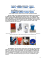
P R O C ESS O V E R V I E W
VillageTech Solutions (VTS) has been developing the SafaPani, a low-cost household
arsenic filtration appliance that utilizes electrocoagulation to filter arsenic from water (Appendix
A). During electrocoagulation, two iron electrodes release iron ions into the water through
electrolysis, which react with hydroxide to form iron (III) hydroxide. Arsenic then complexes
with the iron (III) hydroxide and forms a precipitate, which can be filtered out through sand.
With this chemistry at its heart, the full SafaPani process is summarized in Figure 1. Previous
ENGS 89/90 groups have validated electrocoagulation as an effective means of arsenic filtration
(Appendix B); however, their system lacked a manufacturable housing that is cheap, simple, and
durable enough to succeed in a rural Nepalese home.
Figure 1: A flow chart of the SafaPani process, transforming contaminated water into clean water.
E CONOMIC
AND
S O C I A L C O NST R A I N TS
The median income in Nepal is around $700/year and is even lower in our targeted
region, Nawalparasi (Nepal 2014). Additionally, our end users are very self-sufficient, using
their limited resources to purchase essentials such as kerosene, fertilizer, and batteries.
Therefore, minimizing the production cost of our product is a pivotal factor in generating
demand. Furthermore, our target users live in very rural environments and have limited
opportunities to obtain new parts for repairs or routine maintenance (Appendix C). As a result,
our product is durable and reliable.
PR O B L E M
AND
N E E D ST A T E M E N T
VTS has proved that their unique electrocoagulation method is both simple and effective
at reducing arsenic concentrations to safe levels. However, VTS needs an inexpensive, userfriendly, and manufacturable design to house its arsenic filtration method that will succeed in
Nepal.
1
R E Q U I R E M E N TS A N D SP E C I F I C A T I O NS
The design of SafaPani must meet the required manufacturing, function, and daily use
criteria for a product manufactured in Calcutta and used in Nepal. First, it must be cheaply
manufacturable in order to be practical to distribute to the villagers of Nepal. Second, it must be
easy to use and aesthetically pleasing to our intended users so that it is adopted quickly into the
daily task of collecting water. Third, it must require minimal maintenance and resist wear in
order to maximize device longevity. Table 1 summarizes the identified requirements and
associated specifications necessary to meet these design objectives.
Table 1: A breakdown of the requirements and associated specifications our design must meet to satisfy the
project objectives.
D E L I V E R A B L ES
We are providing VTS with the following four deliverables:
●
●
●
●
SolidWorks files of a custom molded housing for the SafaPani process
Assembly instructions for the design
Working prototype of the design that satisfies the identified specifications
Pictorial user guide showing the user how to safely operate the SafaPani
Delivering these four items will enable VTS to begin the process of bringing
electrocoagulation to Nepalese citizens as a means to filter their arsenic contaminated water. We
have achieved all four of these deliverables, with a main focus on the moldable design, which is
central to moving the device towards production.
2
SO L U T I O N
Throughout the course of the project, we have worked with manufacturing design and
molding experts to create a device capable of meeting all of our requirements and specifications.
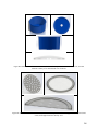
The final product is shown in Figure 2.
Figure 2: Assembled device and exploded diagram detailing each component of the SafaPani design.
Our design consists of three molded plastic containers: a reaction vessel that houses the
electrocoagulation process, an outer shell that holds the reaction vessel and the filtration sand,
and a 65 L reservoir tank that holds clean water (Alternative views and dimensioned drawings
for manufacturing can be found in Appendices D and F). The containers are designed such that
the reaction vessel nests inside the shell to decrease footprint and add stability (Spec. 16). The
inner reaction vessel sits on the built-in shelf of the shell, and the reservoir holds the shell firmly
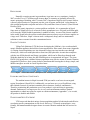
upright with four raised braces. Each container is shown in Figure 3. Manufacturing and
assembly instructions can be found in Appendix F.
The 15 L reaction vessel is a wide bucket with a lip that curves over the edge of the shell
(Spec. 18). The lip of this bucket fits over the rim of the shell, so if the vessel is overfilled or
water is spilled, the device will shed the water and not contaminate the other tanks (Spec.7). The
lip has the added benefit of creating a handle with which the reaction vessel can be lifted out of
the shell to access the sand for maintenance.
The reaction vessel is best manufactured through injection molding due to its wide open
top and inner complexities. Dana Howe, an experienced engineer at the injection molding
company GW Plastics, reviewed our design and confirmed that injection molding is the optimal
3
method of manufacture (Appendix G). He recommended a minimum draft angle of 2˚ and a wall
thickness of 2.5 mm with a tolerance of 0.2 mm, which we have integrated in our design.
Figure 3: The three main containers of the SafaPani: the reaction vessel, shell, and reservoir.
A flapper valve in the bottom of the reaction vessel is used to drain the water into the
sand filter after the electrocoagulation process is complete. It is recessed in the bottom of the
bucket to ensure all of the water drains. The user must pull the nylon cord attached to the flapper
to release the water into the sand filter once the reaction is complete.
The electrodes are secured to the bottom of the reaction vessel with strips of Velcro
screwed into the bottom of the bucket with 8-32 nylon screws and nuts with rubber washers. The
Velcro securely holds the iron bars vertically while still providing access to remove and replace
them, so that the hydrogen bubbles produced between the electrodes can escape upwards (Spec.
11). O-rings with a cross-sectional diameter of 2.5 mm are placed around the electrodes to keep
them properly spaced apart, even with degradation of the iron over time.
The electronics are potted in epoxy and screwed to the inside wall of the reaction vessel
with 8-32 nylon screws, nuts, and rubber washers. The electronics are placed near the rim of the
reaction vessel so the LEDs can be easily viewed through the clear lid to notify the user. Two
wires connect the potted electronics to the electrodes and two wires lead from the electronics to
the battery external to the device.
The shell is a tall bucket in which the reaction vessel nests. The bottom section is a
smaller diameter than the top to create a ledge on which the reaction vessel can rest. The sand is
stored in the base of this container beneath the reaction vessel so that the sand is easily accessible
to the user by lifting the reaction vessel out of the shell (Spec. 10). With the height of sand
constrained to a minimum 20 cm, minimizing the diameter of the sand decreases the overall
weight.
Mr. Howe recommended that the shell be manufactured through injection molding as
well with 2.5 mm thick walls and a tolerance of 0.2 mm. It has the minimum draft angle of 2˚ to make the most stable shape that is still injection moldable. The shell is 42 cm tall and with an
upper diameter of 17.5 cm and smaller bottom diameter of 15 cm, with the decrease in diameter
occurring 18 cm from the top. A slope is molded into the bottom of the shell to allow the water
to drain out easily. A raised ring along the inside of the bottom of the shell with spokes pointing
to the drain will provide support for the sand screen while also increasing surface area for the
water to drain out of the sand.
The sand screen rests on the bottom of the inside of the shell and retains the sand while
allowing the filtered water to pass through. The sand screen fabric is 100% nylon with a rip-stop
weave. The fabric is held between two disks of high density polyethylene (HDPE) and fixed with
urethane-based glue. One piece of the HDPE is shaped as an open annulus to allow the least
4
impedance to water flow, while the second piece is a disk with many 3 cm diameter holes to
provide structural support for the sand. A low-cost, FDA approved rubber is adhered with glue
around the disk to form a tight seal to the inner walls of the shell. The 20 cm of sand rests on top
of the sand screen (Spec.6). This 20 cm height was determined optimal for filtration by the
previous ENGS 89/90 team (Appendix B). On top of the sand rests a dispersion plate
manufactured by being stamped out of a sheet of HDPE.
A transparent, domed lid fits over the top of the reaction vessel and snaps into place.
There are grooves in the lip of the reaction vessel to provide a channel for the wires and flapper
valve pull cord to exit the device without affecting the ability of the lid to close securely. The
dome shape of the lid discourages users from placing objects on top of the device and also sheds
water. The lid will be thermoformed out of clear polyethylene terephthalate.
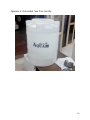
The shell rests on the rotomolded reservoir tank. Our tank design is similar to an existing
rotomolded tank found in Calcutta (Appendix H), albeit with a 65 L capacity and a semicylindrical shape to fit against a wall (Spec. 8). It is 30 cm tall with a radius of 30 cm and has a
wall thickness of 3 mm. It has horizontal ribbing for structural support as well as four angled
supports to brace the shell. A valve at the bottom of the reservoir allows the user to dispense the
water when needed. The reservoir tank is raised on a cinderblock stand to allow for adequate
spacing to fill a large cooking pot underneath the output valve (Spec. 13).
The full device is 0.75 m tall and will sit 0.3 m off the ground with the stand, bringing the
full height to about 1 m, which is slightly above the hip level of an average adult. Minimizing the
height of the device has been a driving objective, as Nepalese citizens are required to fill the
reaction vessel from the top with 15 L (15 kg) of water.
Safety and reliability are paramount to the successful use of our device. A household
water filter has the potential for accidental consumption of arsenic and thus demands precision
and care when operating the device. As with any manufactured device, there are associated risks
and reliability issues, which we have addressed in Appendix I. When operated according to the
pictorial user manual, though, our device successfully takes in contaminated water, and outputs
clean water that is free of debris, color, and odor (Spec. 17).
Beyond meeting our design requirements and specifications, the manufacturing costs are
minimized due to utilizing industry standards for molding methods and using common shapes
and materials for cut pieces. The light-weight plastic containers make the device easily
transportable when empty (Spec. 2), and also are durable for the 5 year lifespan of the device
(Spec. 14). Every manufacturing step we have deemed necessary, is possible in Calcutta (Spec.
3). The device is battery powered and holds a family’s daily volume of water (Spec. 4). The
shape and supports built into the device make it safe and stable (Spec. 5). The simplicity of the
design aids in user-friendliness, and ease of maintenance (Specs. 10, 11, 12, 15). The wide open
top allows users to easily pour water from their collection bucket into the reaction vessel. The
flat side of the tank allows the device to be put against a wall maximizing storage capacity while
still minimizing footprint (Spec. 16). Finally, we have confirmed the compatibility of our full
size design with the aluminum molds required for injection molding with draft analysis in
SolidWorks (Spec. 3) (see Appendix E).
5
E L E C TRONIC C IRCUIT
The SafaPani system requires an electronic circuit to control the electrocoagulation
process. The following list outlines the objectives of the circuit.
1) Controls the current to the two iron electrodes submerged in the reaction vessel.
2) Measures current through the electrodes and shuts the process off at a designated coulomb limit. Doing so
enables the SafaPani to introduce a precise amount of iron into the water in order to consistently filter
arsenic.
3) Measures the battery voltage and shuts off the system when the battery is low.
4) Signals to the user when the reaction vessel is undergoing electrolysis, when it waiting for the iron to mix
with the arsenic, and when the process is over. This lets the user know when it is time to open the valve
from the reaction vessel to the sand filter.
Figure 6 shows the circuit schematic and board layout of the printed circuit board, as well
as an overview of the microcontroller process used to accomplish the four tasks listed above. The
board is encased in a clear epoxy that waterproofs the circuit and allows the user to see the signal
LEDs on the board. A more detailed description of the circuit design, including a user manual
and the microprocessor code, can be found in Appendices M and N, respectively.
Figure 6: Microprocessor flowchart, circuit schematic, and printed circuit board layout.
T EST I N G
To validate that the SafaPani design described above satisfies each required specification,
we performed qualitative and quantitative tests. The following section describes each test and its
results.
F inite Element Analysis
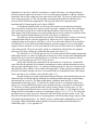
A finite element analysis was conducted in SolidWorks to validate the structural integrity
of the design. The results can be found in Figure 4. The maximum weight of the full device (with
15 L of water in the reaction vessel plus 20 cm of wet sand in the shell) weighs about 45 kg and
creates a load of 506 N on the reservoir tank. Under these loading conditions the reservoir will
deform 1.5 cm downwards in the center of the top, but will not fail. The maximum stress endured
by the tank is about 12.5 MPa. With a yield strength of HDPE is 26 MPa, our design has a factor
of safety of 2.08. With the weight and shape of the device, a force of 100N applied from the side
to the top of the device would be required to push over the shell.
6
Figure 4: FEA analysis of the reservoir tank. Left: Maximum stress of 12.50 MPa. Right: Maximum deflection of
1.501 cm as a result of the applied load of a full reaction vessel and shell.
Sand Screen F abric
One of the main design challenges lay in creating a method to contain the sand while
allowing water to pass, and be strong enough to withstand the weight of a 20 cm high column of
sand. With these two design requirements in mind, we examined the sand permeability and flow
rate performance of cotton, polyester, polyester-cotton, nylon, agricultural, Weed-Block fabric,
and mesh screening. In order to test a fabric’s ability to contain sand, a pouch was constructed out of each fabric and a constant amount of sand was added. Water was passed through each
pouch of sand and collected to determine if any sand escaped. In order to decide which had the
optimal flow rate, 1 L of water was timed while it was poured through each sand pouch
(Appendix J). The agricultural fabric was the strongest but had the slowest flow rate. The WeedBlock fabric had the fastest flow rate, however, it was prone to inelastic deformation under
stress, so it was also rejected. Therefore, the only materials that satisfied our two design
requirements were cotton, nylon, polyester, and polyester-cotton fabric. However, cotton is a
naturally grown fiber and is subsequently prone to degradation in the warm, wet areas it would
be placed. Furthermore, both polyester and polyester-cotton fabric had high flow rate and
durability; however, they both ended up retaining water and required a long time to dry.
Comparatively, nylon not only had a high flow rate and durability, but it also was quick-drying.
Therefore, we chose nylon fabric over a polyester or polyester blend fabric to use in our final
design.
User Testing
In order to validate and improve upon our design, we asked volunteers to carry out tasks
that would mimic both daily use and necessary maintenance. In our first two tests, the subjects
were asked to replace the electrodes and change the sand. In order to measure the ease of this
maintenance, we timed the users with the idea that shorter time correlates to ease of replacement
(Appendix K). In our next test, the subjects were asked to use our device as intended by
following a pictorial step-by-step guide in order to obtain feedback on the clarity of our
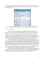
instructions (Appendix L). We also determined average flow rates for processing the 15 L of
water that each subject filtered, which is displayed in Figure 5. After completion, the subjects
were surveyed on the ease of maintenance, intuitiveness, ease of use, and helpfulness of the
pictorial guide. Finally, the subject was asked one way in which they would improve our device
to not only narrow down problem areas in our design, but also highlight any unique problem we
7
may have overlooked (Appendix K). Ultimately, subjects thought that our device was fairly
intuitive and easy to use.
Figure 5: Flow rate results of the working SafaPani prototype. The average flow rate over all subjects was 0.676
L/min.
W O R K I N G PR O T O T Y P E
Our prototype represents the ideal, moldable design constructed to the best of our ability
without utilizing custom molding. Since the estimated die costs for injection and rotomolding are
over $50,000, we decided that we would produce a highly representative and fully functioning
prototype with off the shelf components (Appendix O). In this way, we avoided spending the
substantive cost of tooling the mold before user testing revealed any necessary changes in the
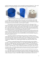
design. In Figure 8 below the ideal model and the working prototype are displayed side by side.
As one can see, the general shape of the molded design is conserved in the prototype. The
reaction vessel still nests within the shell, with the curved lip of the reaction vessel extending
over the edge of the shell. Additionally, the shell in the working prototype contains the
dispersion plate, sand screen, and sand found in the moldable design. To replicate the topography
of the bottom of the shell in the molded design, marbles were used. However, the overall height
of the prototype is taller than that of the molded design. The price of the working prototype is
$127.19 (Appendix P).
8
Figure 8. Ideal, moldable design and working prototype side by side.
E C O N O M I CS
After the model was researched, tested, and finalized, quotes for each component of our
design were compiled in order to determine a final Bill of Materials for our device. The
summarized unit cost for each component in our final design is shown in Table 2.
Table 2: A detailed Bill of Materials for the molded SafaPani device. Unit pricing for a production run of 1000
devices in the U.S. and adjusted for Calcutta is shown (Spec.1).
In order to obtain estimates for injection molded parts, we consulted with our
manufacturing contact, Dana Howe. The additional tooling and assembly estimates are compiled
in Table 3 to generate a total cost per 1000 units of our device. We consulted with our
established manufacturing contact in Calcutta, Jaydeep Dasgupta, for costs of parts purchased in
India. Our sponsor, who has conducted business in Calcutta, has approximated the cost
9
adjustment factor of goods and services between the U.S. and Calcutta as a 50-70% discount.
Thus, we will convert our prices for production determined in USD by a factor of 0.6 to estimate
the total cost in India.
Table 3: A breakdown of the costs associated with molding, tooling, and assembly. By incorporating these costs
with our Bill of Materials, we can estimate the total cost of producing 1000 units of our device.
PA T H W A Y
TO
SO L U T I O N
The process of developing, building, and validating the SafaPani design involved
research, consultations, and most importantly, design iterations. We began by researching the
problem of arsenic contamination in Nepal in depth, including the state of the art already
designed to solve it. The shortcomings of the Sono Filter and Kanchan Filter, two popular
competitors, were readily apparent (Appendices C and Q). For example, both have brittle and
weak features which protrude from the device and could shear off. Previous ENGS 89/90 teams
and Dartmouth Humanitarian Engineering (DHE) have done a lot of work in solving these
issues. The most recent iteration of the Dartmouth design used two large nested buckets.
Considering these designs, it was apparent that plastic molding would be large part of the
project. As a result, part of our research involved investigating plastic manufacturing processes,
specifically injection molding, blow molding, and rotational molding. Each process has its own
advantages, general practices, and common materials. Consulting specialists such as Dana Howe
and Professor Ulrike Wegst gave us expert opinions and guidance on these topics (Appendix R).
Using the Cambridge Engineering Selector (CES) software, we were able to evaluate over 100
materials based on their relevant properties (Appendix S). Our requirements whittled the list to
just 19, and helped us select HDPE as the cheapest options for many of our parts.
In parallel with researching manufacturing processes, we followed a regimented design
strategy to develop the form and function of each piece of the SafaPani. Figure 9 summarizes the
steps involved in our process. The arrow from testing back to brainstorming highlights the
importance of the many iterations we have made to arrive at our final solution.
10
Figure 9: The high-level design method we used to develop each component of the SafaPani.
Each piece of the SafaPani underwent a design progression, improving with input from
our sponsor, expert consults, and testing results. Figures 10 and 11 show the many overall
SafaPani forms and corresponding prototypes used to test specific pieces of them. The volume,
footprint, and material of the design changed immensely throughout the project, as we became
more knowledgeable about the culture and needs of our user. For example, reducing the overall
batch size and reservoir volume to 15 L and 65 L respectively better fits into the average
Nepalese household daily use requirement.
Figure 10: Progression of SolidWorks modeling: 2012 ENGS 89/90 final model (image from Stefan Deutsch), our
PDR SolidWorks model, our CDR SolidWorks model, and our final SolidWorks model.
Figure 11: Progression of physical prototypes: DHE 2013 prototype, VTS 2014 summer prototype, our PDR
prototype, and our final working prototype model.
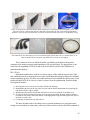
Each form shown above also requires a holder for the electrodes and a water-permeable
sand screen to contain the sand. For the most part, these pieces are independent of the overall
form, and were therefore optimized independently. The electrode holders were designed to be
simple and strong, while also allowing for easy removal of the electrodes. The sand screen’s main design challenge lay in designing a simple solution that would let water, but not sand, to
pass. Figures 12 and 13 show the main design progressions used to reach the final, elegant
solutions.
11
Figure 12: Progression of Electrode Holder design: Angled laser cut rectangles with feet designed by VTS with 2
mm center section. U-shaped with separate 2 mm shim. Trapezoidal clips with 2 mm nub and perpendicular
stabilizers. Velcro straps screwed into floor of reaction vessel and electrodes spaced by a 2 mm diameter O-ring.
Figure 13: Progression of Sand Screen design: Four types of tubing tested; silicone A35 (on hardness scale), silicone
A40, rubber latex A35, and neoprene A61. Two structural support options; disk with 1.5” diameter holes, or ‘X’. Fully assembled sand screen option with rubber latex A35 and ‘X’ style support.
These iterations led to our final deliverable: a moldable, nested-bucket design that
conforms to the unique pressures and constraints of life in rural Nepal. The progression of our
work from the beginning of ENGS 89 and to the end of ENGS 90 leaves the SafaPani as a
manufacturable product.
N E X T S T E PS
Dartmouth students have worked on various aspects of the SafaPani project since 2009.
Our contribution to the system has been to create a manufacturable design to house the validated
electrocoagulation process. We have succeeded in this goal and validated the effectiveness of our
product during ENGS 89/90. However, there is always room for optimization. Possible further
investigations include:
1) Recessing the valve in the reservoir tank to shield from shearing
2) Manipulating the form of the top of the reservoir tank to inhibit contaminants from entering the
tank such as with a ridge or trough
3) Manufacture the printed circuit board with holes for screws to eliminate an assembly step
4) To improve the seal on the sand screen, an oversized ring of rubber sheeting could be inserted
between the two plastic disks such that the overhanging rubber edge deforms against the walls of
the shell to create a seal
5) Completely minimize the cost of the device
The next step that needs to be taken to move towards production is to perform arsenic
testing on our prototype to ensure that it effectively filters arsenic to below the WHO standard of
12
10 ppb. DHE is planning to conduct such a test in the coming spring of 2015. Successful arsenic
filtration results will fully validate the functionality our design.
Another step is to perform field testing in Nepal and to learn more about how the
SafaPani will fit into a villager's home. Building a small number of our working prototype units
will allow VTS to quickly and cheaply test the design in the real world, while acquiring usability
data to further validate and perhaps enhance the design. Ideally, VTS will bring these prototypes
to Nepal in the summer of 2015. In parallel with field testing, DHE should begin to apply for
grants or fundraise for the relatively large cost of molding and tooling for molding the three main
pieces of the design and the initial production run.
Successful small scale tests of the working prototype in Nepal can provide VTS with the
confidence to pay for the prototype molds necessary to create the fully custom SafaPani design.
The production of these molds permits VTS to cheaply fabricate the reaction vessel, shell, and
reservoir, and begin the process of bringing the SafaPani into the hands of the people who need
them most.
13
W OR KS C I T E D
"Arsenic in drinking water seen as threat." Associated Press. August 30, 2007.
"Water-related Diseases." WHO. Accessed October 13, 2014.
http://www.who.int/water_sanitation_health/diseases/arsenicosis/en/.
"Nepal." World Bank. Accessed October 13, 2014. http://data.worldbank.org/country/nepal.
Husband, Dan, Baskin, Jeremy, Piersma, Deutsch. ENG S 89 F inal Design Review: SafaPani —
Arsenic-free Water. 2012.
14
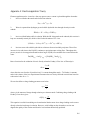
A ppendix A : E lectrocoagulation T heory
Electrocoagulation can be viewed as a four-step process once a current is placed through the electrodes:
1.
Iron is oxidized at the anode and released into solution.
Fe(s) → Fe2+(aq) + 2e2.
Water is separated into hydrogen gas and soluble hydroxide ions through electrolysis at the
cathode.
2H2O(l) + 2e- → H2(g) + 2OH-(aq)
3.
Iron is oxidized further while in solution. With the OH- being made at the cathode, this reaction is
kept at a reasonably neutral pH, which is ideal for the formation of Fe3+ ions.
½ H2O(l) + ¼ O2(aq) +Fe2+(aq) → Fe3+(aq) + OH- (aq)
4.
Iron ions react with soluble hydroxide in solution to form an insoluble precipitate. These flocs
increase in size with time as the Fe(OH)3 continues to precipitate onto existing flocs. Throughout this
process, arsenic is also trapped and bound to these larger Fe(OH)3 flocs and therefore removed from the
water.
Fe(OH)3(s) + AsO43-(aq) → [Fe(OH)3 * AsO43-](s)
Rate of reaction for the oxidation of iron is directly related to Faraday’s First Law of Electrolysis:
𝑑𝑛 =
𝐼 ∗ 𝑑𝑡
𝐹 ∗ 𝑧
where dn is the rate of moles of iron dissolved, I is current through the anode, F is Faraday’s constant, and z is the valence of the iron. Experimental literature observes closely followed reaction rates based on
a theoretical value for z = 2.
We can also define a charge loading parameter seen below:
𝑞=
𝐼∗𝑡
𝑉
where q is the amount of charge through solution per volume treated. Combining charge loading with
Faraday’s Law above gives:
𝑑(𝐹𝑒) =
𝑞
𝐹∗𝑧
This equation is useful for modeling an electrochemical batch reactor since charge loading can be seen as
directly related to iron dosage in solution. However, oxide buildup on the electrodes over time can
degrade the quality of the reaction and dissolve less iron than theoretically predicted.
A1
A ppendix B: Previous E N GS 89/90 T esting and O ptimization
Figure B1: Final [Fe] and [As] at initial [Fe] = {15,20,25,30 ppm} & [As]=200 ppb
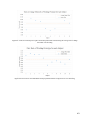
Figure B2: Final [As] at [P] = {1, 2, 4 ppm} at various initial [Fe]. Initial [As] = 200 ppm.
Figure B3: Comparison of effluent [Fe] & [As] at 15, 20, and 25cm filter depths. Initial [As] = 200 ppb
and Initial [Fe] = 20 ppm.
B1
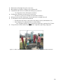
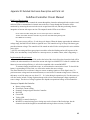
A ppendix C : Jeremy and K atie Skype Meeting 2/21/15
The following are notes from a video conference call on Feb 21, 2015 with Jeremy Baskin and Katie
Zhang, two Dartmouth Humanitarian Engineers who spent the winter 2015 abroad in Nepal researching
the current water situation and preparing for the potential distribution of the SafaPani system.
●
Some Nepalese villages have overhead tanks which distribute to community taps
○ Began only 3-4 years ago but look long-term
○ Government is building 4-5 tanks per year
○ Each tank can serve 1-2 hundred households
○ Each tap serves 4-5 houses
○ Registration fee to use
○ Allowed to collect unlimited amount twice a day
○ Water from overhead tanks is “not contaminated” (50 ppb arsenic)
■ Currently being tested
○ $40,000-60,000 upfront costs supplied by:
■ 80% government and NGOs/international donors
■ 19% villagers in terms of unskilled labor
■ 1% cash from users
○ Lifespan-relatively long term
○ Wealthier have spigot nearer to their homes, live closer to highways
●
Kanchan Filter
○ $75 - $100 for household filter with green pretty tiles for wealthy people
○ 5800 rupees for cheap kanchan filters
○ $4 subsidized price from NGO, entrepreneurs sell them to the NGOs
○ Looks nice, easy to clean
○ Large square shape fit well in home
○ They like the concrete. Looks more durable.
○ Put in corner, next to counter
○ 1ft by 1ft footprint of a microwave
○ 4 ft tall
○ Wealthier paid full price for Kanchan filter $76~100 unsubsidized
■ Green tile added to basic filter to make it look nicer.
■ Place in corners of kitchen (1ft x 1ft footprint x 4ft tall)
○ Proud of their filters.
●
New Trunz filter on the market.
○ Sell 20L bottled water, like water coolers.
○ Pay to refill
○ Easy to buy clean water
○ Expensive to buy $60,000
Use filtered water for drinking and cooking, but not bathing
Daily water usage for family/household (5 people) is 20-40L.
●
●
C1
●
●
●
●
●
●
●
Bath at tube well straight from well, not an issue.
Most nepalese are farmers, welding is not a common skill.
Cinderblocks and bricks are available and could prop up our device.
○ 1 ft off ground is fine to fill Nepalese containers
Children aren’t allowed to use the device is most cases.
○ The device is seen as too valuable to be entrusted to children.s
Still pour water into filter whether get it from water tower or straight from well
12 Volt batteries are not common in households
○ Would need to buy battery, solar panels, and recharge system (which doubles cost)
○ Some Nepalese are on the grid, hence no need of battery.
■ Grid shuts off daily at known intervals for load issues, sometimes for 12 hours.
Color preference of Katie and Jeremy. Pastel colors: Light blue, light orange, light green.
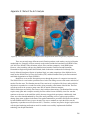
Figure C1: Water collection at a community well tap with few people lining up to fill buckets/containers.
C2
Figure C2: Our friend Nandu standing next to a Kanchan filter that is currently being used as a planter.
Figure C3: Unused SONO filter sitting in the corner of a home in Kunuwar.
C3
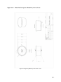
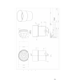
A ppendix D: Detailed V iew of our Molded Design
Figure D1: Manufacturing method and cost for each component.
D1
Figure D2: Detailed view of our device (Clockwise from top right): Front view, top down view, isometric cutaway
view, and side cutaway view.
D2
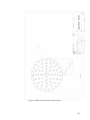
Figure D3: The center of mass of device without reservoir tank and stand is shown. The center of mass is on the axis
in the center of the shell and in the lower half of the shell within the sand.
D3
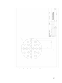
Figure D4: More detailed views of the shell (clockwise from top right): isometric cutaway view, front view, and
close up cutaway view of the raised spokes on the bottom of the shell.
D4
Figure D5: Detailed views of the reaction vessel (clockwise from top left): isometric view, top view, and side
isometric cutaway view. Detailed side view of the lid.
Figure D6: Detailed views of the sand screen (clockwise from top left): Sand screen support disk, Completed sand
screen, Side angled isometric cutaway view.
D5
Figure D7: Isometric view and the front view of the reservoir.
D6
A ppendix E : M anufacturing and Assembly Instructions
Figure E1. The reaction vessel can be molded in a 2-part mold. Draft analysis shows the reaction vessel has
appropriate draft angle for molding
Figure E2. The shell can be molded in a 2-part mold. Draft analysis shows the shell has appropriate draft angle for
molding.
Figure E3. The reservoir tank can be molded in a 3-part mold. Draft analysis shows the tank has an appropriate draft
angle for molding.
E1
A ppendix F : M anufacturing and Assembly Instructions
Figure F1: Engineering drawing of the reaction vessel.
F1
Figure F2: Engineering drawing of the reservoir tank.
F2
Figure F3: Engineering drawing of the dispersion plate.
F3
Figure F4: Engineering drawing of the electrode.
F4
Figure F5: Engineering drawing of the sandscreen ring.
F5
Figure F6: Engineering drawing of the sand screen.
F6
Figure F7: Engineering drawing of the sandscreen support disk.
F7
Figure F8: Engineering drawing of the shell.
F8
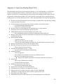
M anufacturing and Assembly Instructions
1. Injection mold reaction vessel and shell, and rotomold reservoir out of high density polyethylene.
2. Pot electronics in epoxy.
3. Screw electronics board into wall of reaction vessel with nylon screws, rubber washers, and nylon
nuts.
4. Insert nylon screw through rubber washer, velcro strip, and inside of reaction vessel for each of
two holes. Secure with rubber washer and nylon nut on outside of reaction vessel.
5. Install flapper valve in depression in bottom of reaction vessel.
6. Connect wires to electrodes using 8-32 steel screws and nuts.
7. Place o-rings (2mm cross-sectional diameter) around individual electrodes.
8. Secure electrodes in velcro straps in upright position.
9. Place reaction vessel inside shell.
10. Place lid on top of reaction vessel.
11. Attach valve to reservoir tank spout.
12. Place tank on cinder blocks.
13. Nest shell into place on top of reservoir tank.
F9
A ppendix G : Dana Howe Meeting Notes 2/13/15
The following are notes from an onsite meeting on February 13, 2015 with Dana Howe, at GW Plastics
located at 239 Pleasant Street, Bethel, Vermont 05032. Mr. Howe is a Systems manager and Cost
Engineer at GW Plastics, a company that specializes in the injection molding of small complex parts for
the automotive and healthcare industries. Mr. Howe showed us on the plant floor to watch the injection
molding process in real time, and help give more context and understanding to the manufacturing process.
●
●
●
●
●
●
●
●
●
●
●
●
●
●
●
●
●
●
●
Reaction vessel and shell should be injection molded, no considerable savings with blow molding
because need inner die anyway
Our store bought working prototype blue chemical container was injection molded
○ Text indentations incorporated into mold
○ Depressions on bottom for strength
Reservoir needs to be blow molded or roto-molded because it’s fully enclosed
Incorporate screw holes into mold, don’t drill after the fact.
Adding threaded neck increases blow molding cost by about ~30%.
○ Blow molded bottles begin as an injection molded tube with threaded neck
Bumps vs. Star shaped cuts in base of shell; Both accomplish increase in drainage surface area to
eliminate drainage mat
How to package and ship
○ “Expensive to ship air”
○ Make sure they nest well into each other
○ Criteria to nest: outside diameter of bottom must be smaller than inside diameter of top
Reaction vessel flared lip will help outer shell hold its shape
Will inject off center for reaction vessel to avoid flapper valve
○ Flow of material will be asymmetric
Tolerance of wall thickness 2.5mm +/- 0.2mm
○ All metric units for international manufacturing
Potential limitations:
○ Food safe approvals
○ Must validate material and once selected, very difficult to deviate
○ Reaction vessel might sink into reservoir
■ Might need to support with internal column (pipe with holes out of plastic)
matweb.com
○ Shows regions that material is available
○ Usually not effective to import
HDPE for reaction vessel, shell, reservoir
○ Not necessarily dimensionally stable
Polystyrene (or polyester) for clear thermoforming
FEA analysis to see if 80lbs can be supported by reservoir.
Might need to increase height so that more support is directly underneath
Add ridges for strength, they don’t add too much complexity to the mold
Draft angles no less than 2 degrees
Stamp dispersion plate and sand screen out of a roll of polypropylene or polyethylene
G1
●
●
●
●
●
●
●
Class 6 material HDPE1245ON DOW FDA approved
○ Material pricing $1.31/lb
○ Smaller quantities for prototype $3-4/lb
Considerations for injection molding
○ Weight of material
○ Cycle time
○ 1 cavity tool
○ 650 ton machine
○ Quality control
○ 0.25 operators per machine but would probably be higher for our pieces
○ Packaging cost: 25 cents a piece for inner bucket, 43 cents a piece for shell
If the shell is too heavy for the tank to support, we can have a column made from a tube with
holes in the sides on end placed under shell for support.
Think of how the device might not be set level in the home, so our design must accommodate for
that through the angles of our design.
Adding a spout to the design is cheap in injection molding
Put as much as possible of the design/manufacturing into the mold
The changing the overall shape of the design can add more support than changing the thickness.
Reaction vessel estimates-per 1000 units
$2144.73-material
493.00-machine
52.17-quality control
217.00-packaging
+
46.58-die maintenance
_______________________________
$3144.63 or about $3 per piece (excluding mold)
$17,000 for mold
Shell estimates (with similar break down)
$5152.38 or about $5 per piece
$22-24,000 for mold
G2
A ppendix H : Rotomolded T ank from C alcutta
Figure H1: Example rotomolded water tank in Calcutta. (Image courtesy of Jaydeep Dasgupta)
H1
A ppendix I: F ailure Modes and E ffects A nalysis (F M E A) and Safety Risk
Assessment (SR A)
Table I1: FEMA analysis results.
I1
Table I2: SRA analysis results.
I2
A ppendix J: Fabric T esting Protocol and Results
Mesh/Fabric Testing Protocol
Procedure:
1. Cut a 14” diameter circle out of each fabric to be tested
2. Place one piece of fabric into ~1.5 gallon bucket (should bunch and look like a coffee filter)
3. Pour 750g of (Home Depot play sand) sand into the bucket with filter
4. Pour 1 L of water through the sand (this step is to saturate the sand with water)
5. Allow water to run through until all water has run through and sand is saturated
6. Pour 1 L of water into bucket and begin timer at first contact of stream with sand
7. Stop timer when drips of water are 5 seconds apart
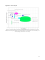
Table J1: This table summarizes the results of the fabric testing. Because of its fast flow rate and durability, nylon
was chosen as the optimal fabric.
J1
A ppendix K : User Testing Results and Q uestionnaire
User Questionnaire
Subject name______________
Date and time of test______________
1. How easy were the electrodes easy to replace? (Circle one, 1 not at all, 5 very)
1 2 3 4 5
2. Was the sand easy to access?
1 2 3 4 5
3. Was the device intuitive to use?
1 2 3 4 5
4. Was the device easy to use?
1 2 3 4 5
5. How helpful was the instructional guide?
1 2 3 4 5
Name one way in which you would improve this device.
_____________________________________________________________
For Group 15 only:
Time to change electrodes_________
Overall running time for device________
Figure K1: This figure shows the questionnaire given to test subjects upon completion of testing. The questions seek
to determine both how intuitive our device is to use and how to improve on the design.
Table K1: This table summarizes the data obtained through user testing.
K1
Figure K2: These five graphs show the ranked (on a 1-5 scale) responses of users to each of our five survey
questions.
K2
Figure K3: Times for each subject to replace electrodes plotted with a line showing the average time to change
electrodes over all testing.
Figure K4: Flow rate for each individual test subject plotted with the average flow rate over all testing.
K3
A ppendix L : Pictorial Instruction G uide and Steps to Perform
Figure L1: Pictorial guide for use of the SafaPani.
L1
The steps in words are as follows:
1.
2.
3.
4.
5.
6.
7.
8.
Close flapper valve
Pour in water
Close lid
Switch on
Wait
Green light will turn on
Pull cord and hook it to wall of outer bucket
Switch off and open tank valve
L2
A ppendix M : Detailed E lectronics Description and Parts L ist
SafaPani Controller Circuit Manual
High Level Requirement
The controller circuit controls the current through the electrodes submerged in the reaction vessel,
and uses LEDs to communicate its internal state to the user. Charge through the electrodes will be
monitored by measuring the current in the circuit at equal time intervals, and then performing discrete
integration of current with respect to time. The outputs from the LEDs are as follows:
Green: Turn ON when mixing time is over. OK to open valve to sand filter.
Yellow: Slow blink when the electrodes are powered. Fast blink during mixing time.
Red: Blink for low battery.
The power source will be a 12 volt deep cycle battery. When the battery approaches the minimum
voltage range, the Red LED will blink to signal the user. The controller will go to sleep if the battery gets
past this minimum voltage. The controller will be turned on and off with a switch placed in series with the
power wires.
<<NOTE: user testing and focus group input is needed to refine the blinking and on/off sequence of the
LEDs, to be sure that they clearly indicate to a non-expert user, in another culture, what is happening.>>
Implementation Requirements
An 8-bit microcontroller will be used as the brain of the circuit. Since the electrolytic load will be
variable, the microcontroller will control the current with logic-level MOSFET. If a Stirrer is added in the
future to increase mixing efficiency, it will also be controlled with a second MOSFET.
To measure charge passed to the water, we will monitor the current in the circuit. To check if the
battery is approaching its lower limit, we will need to monitor the source voltage.
The microcontroller uses a reference voltage to convert an analog signal to a 10-bit digital value. To
perform accurate voltage and current measurement, we need to have a constant voltage source. However,
the battery we will be using can vary from 13.5 – 11.0 volts during its operation cycle. For this reason, we
will also need to include a voltage regulator that provides a lower constant output voltage regardless of
source voltage. The choice of voltage regulator also depends on operational voltage of microcontroller.
Summary of Inputs to the Controller:
● Battery voltage reading
● Electrolytic current reading
● Summary of output signals from the Controller:
● Red LED
● Green LED
● Yellow LED
● MOSFET to control electrolysis
● MOSFET to control stirring [note: stirring may not be a feature of the first designs, but the
electronics should be designed to accommodate stirring in future versions, if needed.
M1
Process Flow
The flowchart in figure K1 describes the method used by the microcontroller to oversee the electrolysis
process. The circuit periodically checks the battery voltage and shuts off the electrolysis process if the
battery is too low. It also checks the current and updates the total charge that has crossed the electrodes.
This value is proportional to the amount of iron ions released into the water, and is used as a measure to
end the electrolysis process. After this charge limit is reached, the controller simply waits for a specified
amount of time to let the iron ions react with the arsenic.
<<NOTE: Testing is needed to determine the amount of charge and the mixing time necessary to react
with common arsenic levels seen in Nepal.>>
Figure M1: SafaPani microprocessor flowchart showing the steps used to control the electrolysis process.
Circuit Description
M icrocontroller
The controller will need to control three LEDs, take current and voltage measurements, and
control current to the electrolysis process via a logic-level MOSFET. We had initially thought of using
ATtiny 85 for the project because of its tiny form factor and low cost. However, the ATtiny85 has only 6
usable IO pins and we will need at least 4 output pins and 3 input pins. For development and testing
purpose, we will also need to have enough memory on chip to collect field data for later analysis.
Therefore it would be best to use a development platform like Arduino Nano for development platform
and use a bigger microcontroller like ATtiny84 for the wide scale production device.
Here are the features of Arduino Nano and ATtiny84 that will be most important to our project:
Arduino Nano:
● Has inbuilt voltage regulator which will make early development process easier.
● Input Voltage limits 7-12 volts.
● Operation logic level voltage: 5
● Analog Input pins: 8
● Digital I/O pins: 14
M2
● Analog to Digital Converter: 10 bits
● 32 KB of flash memory useful for logging data
● USB port of power data stream. <<Note: voltage from USB might be unreliable.>>
ATtiny84:
● $1.50
● 8 KB of non-volatile FLASH memory for code
● 512B EEPROM for non-volatile data
● 512 B SRAM for run-time data
● Programmable in Arduino Environment
● Input Voltage: 2.7 – 5.5V
● Analog Input pins:
● Digital I/O pins:
● ADC channels: 8 at 10 bits
● Timers: 2● Has sleep functionality with significantly reduced power consumption.
● Analog to Digital converter: 10 bits
ATtiny85:
● $xxx
● 8 KB of non-volatile FLASH memory for code
● 512B EEPROM for non-volatile data
● 512 B SRAM for run-time data
● Programmable in Arduino Environment
● Input Voltage: 1.8 – 5.5V
● Analog Input pins + Digital I/O pins: 6
● ADC channels: 4
● Timers: 2
● Has sleep functionality with significantly reduced power consumption.
● Analog to Digital converter: 4 at 10 bits
● 8 KB of flash memory for program
C ur rent M easuring
Initially we had planned to measure the current by measuring the voltage drop across a known
resistor value. However, this wastes a significant amount of energy through heat. For example, the AD
converter has only 10 bits and the voltage resolution would be about 5mv/unit. If we use a 0.1 ohm
resistor, the current resolution would be 50 mA/unit which is insufficient to perform proper charge
calculation.
For this reason, we decided to use a MAX4080 current sense amplifier. The SAUS MAX4080
chip measures voltage drops across a shunt resistor (0.05 Ohms) and magnifies that value by a gain of 60.
More information about the current sense amplifier can be found from the link
(datasheets.maximintegrated.com/en/ds/MAX4080-MAX4081.pdf)
Voltage M easuring
M3
Voltage Measurement is done using a simple voltage divider with two resistors in parallel to the
circuit, and therefore power consumption will be of not a great concern. The resistors, 22.1k and 10k,
drop the maximum battery voltage of 12V down to 3.74V, a value that can be read by the ATtiny84’s ADC.
Voltage Supply to M icrocontroller
The circuit is powered with a 12 Volt deep cycle battery. However, the ATtiny84 microprocessor
requires a 5 Volt power supply. Therefore, a 7805 Voltage regulator is used to supply 5 Volts to the
microcontroller.
In System Programmer
In order to manufacture thousands of these circuits, a simple and robust method of programming
the ATtiny84 is required. A dual inline 6-pin header is soldered to the PCB to allow an AVRISP MKii
device to quickly program the ATtiny84, and the circuit is designed in such a way that in-system
programming is possible.
Circuit Schematic and Board Layout
The individual pieces described above have been synthesized into the circuit schematic shown in figure
L2. The figure shows a high-level diagram of the circuit with its individual components, as well as a
detailed Eagle schematic.
Figure M2: Circuit high level diagram and circuit schematic showing the ATtiny84 microprocessor and the
peripheral components used to make measurements, control the current, and signal the user.
The circuit has been prototyped on a breadboard, shown to work, and designed as a printed circuit board
in EAGLE. Figure L3 shows the board layout for the 1.5”x1.5” circuit board. The bottom holes are for the ground and +12V wires from the battery. The top two holes are for the wires going to the electrodes.
M4
Figure M3: Board layout of the SafaPani control circuit on a 1.5”x1.5” board. Holes have been placed near the wire connections to allow wire straps to add strain relief to the wires.
M5
Full Parts List for the Custom PCB
Table M1: A complete summary of all parts used to construct the SafaPani’s PCB. The information includes the part, quantity, manufacturer, part number, and price.
M6
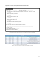
A ppendix N: M icroprocessor Code
//*************************************************************************//
// SafaPani Firmware
// copyright VillageTech Solutions (www.villagetechsolutions.org)
// author: Steve and the Dartmouth 89/90 team Winter 2015
//
// filename: SafaPaniFirmwareV1.ino
// compile with Arduino IDE
//
//*************************************************************************//
/*
This code is used to program an Arduino Nano, or an ATTiny84, to run an
electrolysis process for the SafaPani household arsenic water filter. It
uses a MOSFET transistor to turn on and off current through two iron
electrodes in water. It also senses the current through the electrodes
by using a MAX4080 current sense integrated circuit, and a shunt resistor.
*/
#include <elapsedMillis.h> // from playground.Arduino.cc/Code/ElapsedMillis Not a built
in Arduino library. Must be installed in ..Arduino/Library
// note: elapsedMillis library must be preloaded in the Arduino IDE for this include to work
// [see: http://playground.arduino.cc/Code/ElapsedMillis to download the library,
// and http://arduino.cc/en/Guide/Libraries for instructions on installing the library in Arduino IDE]
#include <avr/power.h> // Library of functions to disable peripherals on the ATTiny84 to limit the power usage
#include <avr/sleep.h> // Library of functions to put the ATTiny in different levels of sleep to limit the power usage
//*************************************************************************//
/*
// ARDUINO NANO PIN LOCATIONS: Enable when using the Arduino Nano as the microcontroller
// Digital Pin locations
const int green_led = 7; // Pin to control the Green LED to signal when process is complete.
const int red_led = 9; // Pin to control the Red LED to signal when the battery is low.
const int MOSFET_pin = 2; // Pin to control the MOSFET to switch on or off current through the electrodes.
// Analog Pin locations
const int yellow_led = 8; // Pin to control the Yellow LED to signal when process is running.
// TODO: I changed pin to analog output for fading. Choose an analog pin for the Yellow LED
const int voltage_divider_pin = A7; // Pin to read the battery voltage with a voltage divider.
const int current_pin = A0; // Pin to read the current through the electrodes with a current sense amplifier.
*/
//*************************************************************************//
//*************************************************************************//
// ATTINY84 PIN LOCATIONS: Enable when using the ATTiny84 as the microcontroller
// Digital Pin locations
const int green_led = 0; // Pin to control the Green LED to signal when process is complete.
const int red_led = 1; // Pin to control the Red LED to signal when the battery is low.
N1
const int MOSFET_pin = 9; // Pin to control the MOSFET to switch on or off current through the electrodes.
// Analog Pin locations
const int yellow_led = 3; // Pin to control the Yellow LED to signal when process is running.
const int voltage_divider_pin = 5; // Pin to read the battery voltage with a voltage divider.
// Note: You must use a pin that is analog input capable.
const int current_pin = 7; // Pin to read the current through the electrodes with a current sense amplifier.
// Note: You must use a pin that is analog input capable.
//*************************************************************************//
// LED Parameters
int yellow_led_brightness = 0; // Variable to keep track of how bright the Yellow LED is
int yellow_led_fade_amount = 1; // Variable to keep track of how fast the Yellow LED fades
// Variables dealing with the charge across the electrodes
float coulomb_count = 0; // Coulombs of charge that have passed through the electrodes. Initialize at 0.
//const int coulomb_limit = 105000; // TODO:(Determine Correct coulomb limit correlated to iron in water).
// Coulomb limit that signals that Electrolysis is over. (Coulombs)
const int coulomb_limit = 5; // TESTING VALUE. Coulomb count setting to be able to test over short timeframe. (Coulombs)
const float Rshunt = 0.05; // Shunt resistor value (Ohms). Used to convert Current sense output voltage to current.
// Variables to keep track of interval times
const long sample_time = 10000; // Time interval between current calculation (ms).
const long mix_time = 1000000; // TODO:(Determine correct mix time) Time to wait after electrolysis (ms).
const long battery_sample_time = 20000; // Time interval between battery voltage checks (ms).
const int red_led_pulse_time = 1000; // Time interval between Red LED toggles when the battery is low (ms).
const int yellow_led_update_time = 60; // Time interval between Yellow LED fade updates (ms).
// Variables used to keep track of time elapsed
elapsedMillis timeSinceCurrentCheck = 0; // Variable to keep track of how long since the current has been checked
elapsedMillis timeSinceYellowLEDUpdate = 0; // Variable to keep track of how long since Yellow LED fade amount has been updated
elapsedMillis timeSinceBattCheck = 0; // Variable to keep track of how long since the battery has been checked
elapsedMillis timeSinceLowBattLEDUpdate = 0; // Variable to keep track of how long since Red LED has been updated
// Variables to convert ADC values into actual voltages
const int bitt = 1024; // Amount of bits output from the ADC
const int VSS = 4600; // Max voltage used to scale the ADC output to a voltage (mV)
// TODO: Check if this value is correct. I found this value in the code sent to the Dartmouth 89/90 Winter 2015 team
// Battery Voltage Parameters
float battery_voltage = 12; // Declare a variable to hold the current battery voltage (Volts). Initialize to 12 to make smoothing work
const float low_battery_limit = 11.5; // TODO: (Determine low battery limit) Low battery voltage limit (Volts)
N2
const float power_off_battery_limit = 11; // TODO: (Determine absolute lowest battery limit) Power off battery voltage limit (Volts)
boolean lowBatt = false; // Initialize boolean to signal when the battery is getting low (below low_battery_limit).
const float voltage_divider_ratio = 3.21; // R1=10kOhms, R2=22.1kOhms, Battery Ratio
>Divider=R1/(R1+R2). Divider>Battery Ratio=(R1+R2)/R1 = 3.21
// This value is used to scale the voltage read from the voltage divider to the actual battery voltage
////////////////////////////////////// Setup //////////////////////////////////////////
// the setup routine runs once the device is turned on or a reset is pressed:
void setup()
{ delay(1000); // Wait one second for transient currents to die out // Ensure no floating pins to help save power ( ATTINY84 Specific )
for(int i=0; i<12 ; i++) {
//pinMode(i, OUTPUT);
//digitalWrite(i, LOW);
}
// Configure the pins of the microcontroller as input and output
pinMode(voltage_divider_pin, INPUT);
pinMode(current_pin, INPUT);
pinMode(green_led, OUTPUT);
pinMode(yellow_led, OUTPUT);
pinMode(red_led, OUTPUT);
pinMode(MOSFET_pin, OUTPUT); // Power saving settings
//power_adc_disable(); // Disable the ADC. Will be enabled when used. //power_usi_disable(); // Disable universial serial bus //power_timer1_disable(); // Disable timer 1 as it is not used
//Serial.begin(9600);
//Serial.println("time Curr Volt Cul");
}//end setup()
////////////////////////////////////// Main Loop //////////////////////////////////////////
// The loop routine runs over and over again forever:
void loop()
{
// Battery Monitoring when low battery is detected, pulse red LED every 2 seconds
// Check the battery voltage every "battery_sample_time" seconds
batteryCheck(); digitalWrite(MOSFET_pin, HIGH); // Turn on the current to electrodes
float instantaneous_current = check_current(); // Calculate the instantaneous current through the electrodes (Amperes)
// Integrate the current to update Coulomb count
// TODO: Fix a bug to correctly calculate the amount of coulombs that have flown across the electrodes
coulomb_count += instantaneous_current * ( (float)sample_time / 1000); //TESTING
// If enough charge has passed, stop the electrolysis process, and start waiting "mix_time" for mixing
if( coulomb_count >= coulomb_limit )
{
electrolysis_process_complete(); // Wait mix_time, and then signal process is complete
}
N3
// TODO: Record the time, current, and cumulative charge
//record_data(current);
// Wait "sample_time" seconds from the the previous time through the loop to save battery.
// Blink the yellow and Red LEDs as appropriate.
wait_and_blink( sample_time );
} // end loop()
//////////////////////////////////////// Functions ////////////////////////////////////////////
// Fade Yellow LED according to "yellow_led_fade_amount" to signal that the process is active.
// Fade faster during mixing, as the process is almost over.
void update_yellow_led()
{
// If enough time has passed. Update the Yellow LEDs fade amount
if(timeSinceYellowLEDUpdate > yellow_led_update_time)
{
// Reset Yellow LED Update time
timeSinceYellowLEDUpdate = yellow_led_update_time; // Update LED brightness yellow_led_brightness += yellow_led_fade_amount;
// Fix any out of bounds problems
if (yellow_led_brightness >= 20)
yellow_led_brightness = 20;
else if (yellow_led_brightness <= 0)
yellow_led_brightness = 0;
// Reverse the direction of the fading at the edges of fade voltages:
if (yellow_led_brightness == 0 || yellow_led_brightness == 20) { // TODO: determine max led brightness (20 seems to give a qualitative max brightness)
yellow_led_fade_amount = yellow_led_fade_amount ;
} // Set the Yellow LED to a new brightness
analogWrite(yellow_led, yellow_led_brightness); }
} // end update_yellow_led()
// If the battery is low, and red_led_pulse_time has elapsed, toggle the Red LED
void update_red_led()
{
if(lowBatt && (timeSinceLowBattLEDUpdate > red_led_pulse_time) )
{
timeSinceLowBattLEDUpdate = red_led_pulse_time; // Reset the timeSinceLowBattLED counter
// Toggle the Red led
if(digitalRead(red_led) == LOW) digitalWrite(red_led,HIGH);
else
digitalWrite(red_led,LOW);
}// end IF LOWBATT
} // end update_red_led()
// Calculate the instantaneous current through the electrodes
float check_current()
{
//power_adc_enable(); // Enable the ADC
float current_val = analogRead(current_pin); // Read the value from the current sense amplifer
//power_adc_disable(); // Disable the ADC
N4
current_val = map( current_val, 0, bitt, 0, VSS ); // Map the binary value read to between 0 and VSS (mV)
current_val = current_val / 1000; // Convert the current_val from mV to Volts
float current = current_val / (Rshunt * 60.0); // Calculate the current using the shunt resistor, and an amplifier scalar of 60
return current;
} // end check_current()
// Check the battery level every battery_sample_time seconds.
// Set lowBatt if battery is low and power off if battery is very low.
void batteryCheck()
{
if(timeSinceBattCheck > battery_sample_time) // Check battery every battery_sample_time seconds
{
timeSinceBattCheck = battery_sample_time; // Reset the time since the battery was checked
battery_voltage = 0.5*(double)battery_voltage + 0.5*(double)readVcc(); // Update Vcc reading with smoothing
if(battery_voltage < low_battery_limit) // threshold set at low_battery_limit for low voltage indication
{
lowBatt = true; // Set lowBatt threshold while(battery_voltage < power_off_battery_limit) // threshold set at power_off_battery_limit to power off if battery too low
{
//goToSleep(); // TODO: Should we just shut the whole device off and wait for reset here?
// i.e. jump to low_battery() function
battery_voltage = readVcc();
}
} else {
lowBatt = false; // If the battery voltage is above low_battery_limit, set lowBatt as false
}
}
} // end batteryCheck()
// Calculate the battery voltage by scaling the value read from the voltage divider
double readVcc()
{ //power_adc_enable(); // Enable the ADC
int sensor_val = analogRead(voltage_divider_pin); // Read the "voltage divider" analog pin
//power_adc_disable(); // Disable the ADC
double voltage_divider_voltage = map( sensor_val, 0, bitt, 0, VSS ); // Calculate voltage (mV) at the voltage divider
voltage_divider_voltage = voltage_divider_voltage / 1000.0; // Convert from millivolts to Volts
double battery_voltage = voltage_divider_voltage * voltage_divider_ratio; // Convert "voltage divider" voltage to battery voltage
return battery_voltage;
} // end readVcc()
// Battery is too low to continue electrocoagulation
// Turn on the Red LED and wait until device is shut down
// TODO: CURRERNTLY NOT USED. Should we jump here if battery is too low to continue?
void low_battery()
{
// Turn off the current to electrodes
digitalWrite(MOSFET_pin, LOW);
N5
// Turn off Green and Yellow LEDs
digitalWrite(green_led, LOW); // Turn off Green LED (should already be off)
digitalWrite(yellow_led, LOW); // Turn off Yellow LED
// Turn Red LED on
digitalWrite(red_led, HIGH);
// Wait until device is shut off
wait_for_shutdown();
} // end low_battery()
// Electrolysis is done. Turn off current to electrodes, wait mix_time while blinking
// the Yellow LED, and then turn on the Green LED and wait for device to be shut off
void electrolysis_process_complete()
{ digitalWrite(MOSFET_pin, LOW); // Reaction over. Turn off the current to electrodes
yellow_led_fade_amount *= 2; // Double the speed of the Yellow LED fading
wait_and_blink( mix_time ); // Wait for iron and arsenic to mix and react
// Mixing over, light the Green LED and shut off the Yellow and Red LEDs
digitalWrite(yellow_led, LOW); // Turn off Yellow LED
digitalWrite(red_led, LOW); // Turn off Red LED
digitalWrite(green_led, HIGH); // Turn on Green LED
// Wait until device is shut off wait_for_shutdown();
} // end electrolysis_process_complete()
// TODO: Data recording
// Record data values for later analysis
void record_data( int current )
{
float time = millis();
time = time/1000.0;
Serial.print(time);
Serial.print(" ");
Serial.print(current);
Serial.print(" ");
Serial.print(coulomb_count);
Serial.print(" ");
} // end record_data()
// Wait time_to_wait seconds while still blinking the yellow LED
void wait_and_blink( long time_to_wait )
{
// Wait for time_to_wait to pass while Fading the yellow LED
while( timeSinceCurrentCheck < time_to_wait )
{
// Fade the Yellow LED if enough time has passed
update_yellow_led();
// If the battery is low, and red_led_pulse_time has elapsed, toggle the Red LED
update_red_led(); }
// Reset timeSinceCurrentCheck
timeSinceCurrentCheck = 0;
} // end wait_and_blink()
// Simply loop until the device is shut down
void wait_for_shutdown()
{
// Turn on the appropriate LEDs
digitalWrite(yellow_led, LOW); // Turn off Yellow LED
N6
digitalWrite(green_led, LOW); // Turn off Green LED
digitalWrite(red_led, HIGH); // Turn on Red LED
power_all_disable(); // Disable all peripherals
// TODO: Go to sleep here? We still want the Red LED lit up
while(1) {} // Wait for a full reset
} // end wait_for_shutdown()
N7
A ppendix O : Wor king Prototype Assembly
1. Empty 14 gallon, taper-sided chemical container
2. Fill bottom with 1” of marbles to fill in depressions and to increase surface area for water flow.
3. Add sandscreen and 8 inches of sand.
4. Cut 2.5” diameter hole in 4 gallon bucket for flapper valve and drill two small holes for nylon screws to secure velcro for electrode holders. Order of assembly
on screw: 1” rubber washer, velcro, put through hole in bucket, 1” rubber washer, finish with nylon nut. Next, place one rubber o-ring around each iron bar and
then strap the pair of bars in with velcro.
5. File two channels in rim of reaction vessel. One for electrode wires, and the
other for the flapper pull cord.
Figure O1: Assembly instructions for the working prototype.
O1
A ppendix P: Wor king Prototype Bill of M aterials
Figure P1: Bill of materials for the working prototype.
P1
A ppendix Q : State of the A rt A nalysis
Figure Q1: Left: SONO Filter set up in a Nepalese home. Right: Kanchan Filter being used by a Nepalese woman.
There are currently many different arsenic filtration products on the market, varying in filtration
method and size. Examples of filters currently on the market include the household- sized SONO Filter,
ALCAN Filter, READ-F Filter, Kanchan Arsenic Filter, and the community- sized SIDKO plant.
However, after consulting with previous SafaPani team member Chad Piersma and Dartmouth
Humanitarian Engineering leader Meili Eubank, both of whom have conducted a field study of the
heavily affected Nawalparasi district of southern Nepal, two main competitors of the SafaPani device
stood out: the SONO Filter by Filters for Families (FFF) and the Kanchan Filter by the Environmental
and Health Organization in Nepal (ENPHO).
Both filters use an arsenic absorption process through the means of a composite iron material.
The SONO Filter is a two-bucket system that uses a bed of iron fillings to react with arsenic and a bed of
sand to filter the water. The Kanchan Arsenic Filter consists of a top bucket full of rusty nails and brick
chips that is suspended over a sand filter with a piping assembly at the bottom of the bucket. The filter
uses the pressure in the system to pump water into an outside collection container.
While both designs successfully filter arsenic, they both have shortcomings. The Kanchan filter not only
requires many parts and a complex assembly, but also suffers from an incredibly slow flow rate that
continues to decrease as the sand filter quickly becomes clogged with precipitates. Additionally, both
filters were often found abandoned by users after small protruding valves or piping acquired minor
damage from minor accidents in the home. Disregarded maintenance procedures and inefficient subsidies
by both ENPHO and FFF have given no incentive for users to maintain or repair their filter, nor the
opportunity to purchase new ones (Piersma 2013). Therefore, a robust, inexpensive design coupled with a
well-designed marketing and business model is needed to successfully implement the SafaPani
technology into Nepali households.
Q1
A ppendix R: E xpert Consultations
Table R1: A summary of the consulted experts, their specialty, and the major takeaways.
R1
A ppendix S: C ES A nalysis
Figure S1: CES software plotting yield strength over price for materials that are good insulators, have excellent
durability when submerged in freshwater, have excellent durability in a rural atmosphere, have fair durability in UV
radiation (sunlight), and less than 137 lb/ft3 density.
S1