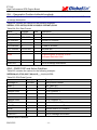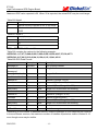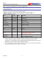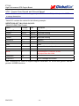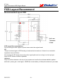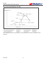
1
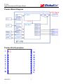
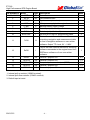
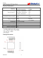
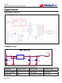
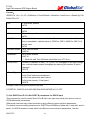
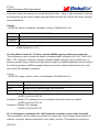
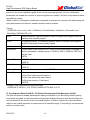
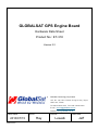
GLOBALSAT GPS Engine Board
Hardware Data Sheet
Product No : ET-318
Version 2.2
Globalsat Technology Corporation
16F., No. 186, Jian-Yi Road, Chung-Ho City, Taipei
Hsien 235, Taiwan
Tel: 886-2-8226-3799 Fax: 886-2-8226-3899
E-mail : [email protected]
Website: www.globalsat.com.tw
Issue Date
2010/07/15
2010/7/15
APPR
CHECK
Ray
Luwalk
-1-
PREPARE
Jeff
ET-318
High Performance GPS Engine Board
Product Description
Product Description
ET-318 is a compact, high performance, and low power consumption GPS engine board. It uses
SiRF Star III chipset which can track up to 20 satellites at a time and perform fast TTFF in weak
signal environments. ET-318 is suitable for the following applications:
z Automotive navigation
z Personal positioning
z Fleet management
z Mobile phone navigation
z Marine navigation
Product Features
z
z
z
z
z
z
z
z
SiRF star III high performance GPS Chipset
Very high sensitivity (Tracking Sensitivity: -159 dBm)
Extremely fast TTFF (Time To First Fix) at low signal level
Two serial ports
4Mb flash
Built-in LNA
Compact size (15.2mm * 14 mm * 2.4mm) suitable for space-sensitive application
One size component, easy to mount on another PCB board
z
z
Support NMEA 0183 V2.3 (Output: GGA, GSA, GSV, RMC, VTG, GLL, ZDA)
Support SiRF binary protocol
2010/7/15
-2-
ET-318
High Performance GPS Engine Board
Product Block Diagram
Product Pin Description
2010/7/15
-3-
ET-318
High Performance GPS Engine Board
PIN Number(s)
Name
Type
Description
1,3,9,18,19
GND
P
2
RF IN
RF
4
RESET_N
I
System reset (active low)
5
VCC
P
Main power supply to the engine board.
6
V_BAT
P
Backup battery supply voltage
7
RxD1
I
Serial input (default null)
8
TxD1
O
Serial output (default null)
10
BOOTSEL
I
Set this pin to high for programming flash.
O
This is the main transmits channel for
outputting navigation and measurement data
to user’s navigation software or user written
software. Output TTL level, 0V ~ 2.85V.
This is the main receive channel for receiving
software commands to the engine board from
SiRFdemo software or from user written
software.
11
TxD0
Note
Ground.
GPS antenna input
1
2
12
RxD0
I
13
GPIO1
I/O
General –purpose I/O
2,3
14
GPIO14
I/O
General –purpose I/O
1,3
15
TIMEPULSE
O
One pulse per second output.(1PPS)
2,3
16
GPIO13
I/O
General –purpose I/O
1,3
17
GPIO15
I/O
General –purpose I/O
1,3
<Note>
1. Internal pull-up resistor (100KΩ nominal).
2. Internal pull-down resistor (100KΩ nominal).
3. Default input at reset.
2010/7/15
-4-
1
ET-318
High Performance GPS Engine Board
Electrical Specification
Absolute Maximums Ratings
Parameter
Min.
Typ.
Max.
Conditions
Unit
POWER Supply
Main power supply
3.1
Backup battery supply
2.0
Main power supply Current
23
3.5
V
3.5
V
27
mA
Backup battery supply Current
4.5
5
5.5
Interface (VCC = 3.3V, VBAT= 3.3V, Operation Temp.= 25℃)
uA
High Level input Voltage
0.7*VDD
3.5
V
Low Level input Voltage
-0.3
0.3*VDD
V
-10
10
60
(V=2.85V)
(with Pull Low)
uA
-10
10
-60
(V=0V)
(with Pull High)
uA
High Level input Current
Low Level input Current
High Level output Voltage
3.3
25
0.75*VDD
V
Low Level output Voltage
0.25*VDD
V
RF Input
Input Impedance
50
Operating Frequency
Ω
1.575
Ghz
☆ VDD is 2.85V for SiRF STARIII CHIP
Environmental Characteristics
Parameter
Min
Humidity Range
Typ
5
Operation Temperature
-40
Storage Temperature
-40
Max
95
25
Unit
85
% non-condensing
℃
85
℃
Physical Characteristic
Type 19-pin stamp holes
Dimensions 15.2mm * 14 mm * 2.4mm
2010/7/15
-5-
ET-318
High Performance GPS Engine Board
Receiver Performance
Sensitivity
Time-To-First-Fix
1
2
Horizontal Position Accuracy
3
Velocity Accuracy
4
Tracking :
Autonomous acquisition :
-159dBm
Cold Start – Autonomous
< 35s
Warm Start – Autonomous
< 35s
Hot Start – Autonomous
< 1s
Autonomous
SBAS
< 2.5m
Speed
< 0.01 m/s
Heading
< 0.01 degrees
Reacquisition 0.1 second, average
Max Update Rate 5 Hz
Maximum Altitude < 18,000 meter
Maximum Velocity < 515 meter/ second
Maximum Acceleration < 4G
<Note>
1. -142 dBm ≈ 28dB-Hz with 4 dB noise figure
2. 50% -130dBm Fu 0.5ppm Tu ±2s Pu 30Km
3. 50% 24hr static, -130dBm
4. 50% @ 30m/s
Package Dimensions
2010/7/15
-6-
-142 dBm
< 2.0m
ET-318
High Performance GPS Engine Board
Application
Application Circuit
POWER Circuit
GPS POWER
VIN
C1
22UF/10V
1
2
3
U1
VIN VOUT
GND
CE
NC
L1
5
4
XC6209B332MRN 3.3V
GPS_3V3
BLM18AG121SN1D
C2
C3
10UF/16V
470PF
GPS Active Antenna Specifications (Recommendation)
Frequency:
1575.42 + 2MHz
Amplifier Gain:
18~22dB Typical
Axial Ratio:
3 dB Typical
Output VSWR:
2.0 Max.
Output Impedance: 50Ω
Noise Figure:
2.0 dB Max
Polarization:
Antenna Input Voltage:
2.85V (Typ.)
2010/7/15
RHCP
-7-
ET-318
High Performance GPS Engine Board
OPERATING Description
VCC
This is the main power supply to the engine
board. (3.1Vdc to 3.5Vdc)
VBAT
This is the battery backup power input for the
SRAM and RTC when main power is off.
Without the external backup battery, ET-318
will always execute a cold star after turning
on. To achieve the faster start-up offered by
a hot or warm start, a battery backup must be
connected. The battery voltage should be
between 2.0V and 3.5V.
GND
This is Ground pin for the baseband circuit.
RxD0
This is the main channel for receiving
software
commands
from
SiRFdemo
software or from your proprietary software.
RESET_N
This pin is input low active. This Module has
internal Power on Reset circuit.
TxD0
This is the main transmits channel for
outputting navigation and measurement data
to user’s navigation software or user written
software. Output is TTL level, 0V ~ 2.85V.
BOOTSEL
Set this pin to high for programming flash in
debug mode. If need programming ET-318
Flash, just pull-up 15KΩ resistor to 3.3V.
When ET-318 used in normal function, this
pin just NC.
RxD1
For user’s application (default null).
TIMEPLUSE
This pin provides one pulse-per-second
output from the board, which is synchronized
to GPS time. This is not available in Trickle
Power mode. If do not use it, Just NC.
TxD1
For user’s application (default null).
RF_IN
This pin receives signal of GPS analog via
external active antenna. It has to be a
controlled impedance trace at 50ohm. Do not
have RF traces closed the other signal path
and routing it on the top layer. Keep the RF
traces as short as possible.
2010/7/15
GPIOs
User can use this I/O pin for special functions
(For example, control LED) .ET-318 had GPIO
1 & 13 & 14 & 15.
-8-
ET-318
High Performance GPS Engine Board
SOFTWARE COMMAND
NMEA Output Command
GGA - Global Positioning System Fixed Data
Note – Fields marked in italic red apply only to NMEA version 2.3 (and later) in this NMEA
message description
Table B-2 contains the values for the following example:
$GPGGA,161229.487,3723.2475,N,12158.3416,W,1,07,1.0,9.0,M,,,,0000*18
Table B-2 GGA Data Format
Name
Example
Units
Description
Message ID
$GPGGA
GGA protocol header
UTC Time
161229.487
hhmmss.sss
Latitude
3723.2475
ddmm.mmmm
N/S Indicator
N
N=north or S=south
Longitude
12158.3416
dddmm.mmmm
E/W Indicator
W
E=east or W=west
Position Fix Indicator 1
See Table B-3
Satellites Used
07
Range 0 to 12
HDOP
1.0
Horizontal Dilution of Precision
1
MSL Altitude
Units
Geoid Separation
9.0
meters
M
meters
1
Units
meters
M
Age of Diff. Corr.
meters
second
Diff. Ref. Station ID
0000
Checksum
*18
<CR><LF>
Null fields when DGPS is not used
End of message termination
SiRF Technology Inc. does not support geoid corrections. Values are WGS84 ellipsoid heights.
Table B-3 Position Fix Indicator
Value
Description
0
Fix not available or invalid
1
GPS SPS Mode, fix valid
2
Differential GPS, SPS Mode , fix valid
3
Not supported
6
Dead Reckoning Mode, fix valid
2010/7/15
- 10 -
ET-318
High Performance GPS Engine Board
GLL - Geographic Position-Latitude/Longitude
Note – Fields marked in italic red apply only to NMEA version 2.3 (and later) in this NMEA
message description
Table B-4 contains the values for the following example:
$GPGLL,3723.2475,N,12158.3416,W,161229.487,A,A*41
Table B-4 GLL Data Format
Name
Example
Units
Message ID
$GPGLL
GLL protocol header
Latitude
3723.2475
ddmm.mmmm
N/S Indicator
n
N=north or S=south
Longitude
12158.3416
dddmm.mmmm
E/W Indicator
W
E=east or W=west
UTC Position
161229.487
hhmmss.sss
Status
A
A=data valid or V=data not valid
Mode
A
A=Autonomous, D=DGPS, E=DR
N=Output Data Not Valid
Checksum
*41
<CR><LF>
Description
End of message termination
GSA - GNSS DOP and Active Satellites
Table B-5 contains the values for the following example:
$GPGSA,A,3,07,02,26,27,09,04,15,,,,,,1.8,1.0,1.5*33
Table B-5 GSA Data Format
Name
Example
Message ID
$GPGSA
GSA protocol header
Mode 1
A
See Table B-6
Mode 2
3
See Table B-7
Satellite Used1
07
Sv on Channel 1
1
02
Sv on Channel 2
Satellite Used
Units
Description
…..
Satellite Used1
Sv on Channel 12
2
1.8
Position dilution of Precision
2
1.0
Horizontal dilution of Precision
2
VDOP
1.5
Vertical dilution of Precision
Checksum
*33
PDOP
HDOP
<CR><LF>
End of message termination
Satellite used in solution.
2010/7/15
- 11 -
ET-318
High Performance GPS Engine Board
Maximum DOP value reported is 50. When 50 is reported, the actual DOP may be much larger.
Table B-6 Mode1
Value
Description
M
Manual-forced to operate in 2D or 3D mode
A
2Dautomatic-allowed to automatically switch
2D/3D
Table B-7 Mode 2
Value
Description
1
Fix Not Available
2
2D
3
3D
GSV - GNSS Satellites in View
Table B-8 contains the values for the following example:
$GPGSV,2,1,07,07,79,048,42,02,51,062,43,26,36,256,42,27,27,138,42*71
$GPGSV,2,2,07,09,23,313,42,04,19,159,41,15,12,041,42*41
Table B-8 GSV Data Format
Name
Example
Units
Description
Message ID
$GPGSV
GSV protocol header
Number of
Messages1
2
Range 1 to 3
Message Number1
1
Range 1 to 3
Satellites in View1
07
Satellite ID
07
Elevation
79
degrees Channel 1(Maximum90)
Azimuth
048
degrees Channel 1(True, Range 0 to 359)
SNR(C/No)
42
dBHz
Channel 1(Range 1 to 32)
…….
Range 0 to 99,null when not tracking
…….
Satellite ID
27
Elevation
27
Degrees Channel 4(Maximum90)
Azimuth
138
Degrees Channel 4(True, Range 0 to 359)
SNR(C/No)
42
dBHz
Checksum
*71
<CR><LF>
Channel 4 (Range 1 to 32)
Range 0 to 99,null when not tracking
End of message termination
Depending on the number of satellites tracked, multiple messages of GSV data may be required.
In some software versions, the maximum number of satellites reported as visible is limited to 12,
even though more may be visible.
2010/7/15
- 12 -
ET-318
High Performance GPS Engine Board
RMC - Recommended Minimum Specific GNSS Data
Note – Fields marked in italic red apply only to NMEA version 2.3 (and later) in this NMEA
message description
Table B-10 contains the values for the following example:
$GPRMC,161229.487,A,3723.2475,N,12158.3416,W,0.13,309.62,120598,,*10
Table B-10 RMC Data Format
Name
Example
Units
Description
Message ID
$GPRMC
RMC protocol header
UTC Time
161229.487
hhmmss.sss
Status1
A
A=data valid or V=data not valid
Latitude
3723.2475
ddmm.mmmm
N/S Indicator
N
N=north or S=south
Longitude
12158.3416
dddmm.mmmm
E/W Indicator
W
E=east or W=west
Speed Over Ground 0.13
knots
Course Over Ground 309.62
degrees True
Date
120598
Magnetic Variation2
ddmmyy
degrees E=east or W=west
2
East/West Indicator
E
E=east
Mode
A
A=Autonomous, D=DGPS, E=DR
N=Output Data Not Valid
Checksum
*10
<CR><LF>
1.
2.
End of message termination
A valid status is derived from all the parameters set in the software. This includes the
minimum number of satellites required, any DOP mask setting, presence of DGPS
corrections, etc. If the default or current software setting requires that a factor is met, then if
that factor is not met the solution will be marked as invalid.
SiRF Technology Inc. does not support magnetic declination. All “course over ground” data
are geodetic WGS84 directions relative to true North.
2010/7/15
- 13 -
ET-318
High Performance GPS Engine Board
VTG - Course Over Ground and Ground Speed
Note – Fields marked in italic red apply only to NMEA version 2.3 (and later) in this NMEA
message description
Table B-12 contains the values for the following example:
$GPVTG,309.62,T,,M,0.13,N,0.2,K,A*23
Table B-10 RMC Data Format
Name
Example
Message ID
$GPVTG
Course
309.62
Reference
T
Course
Units
Description
VTG protocol header
degrees Measured heading
True
degrees Measured heading
Magnetic1
Reference
M
Speed
0.13
Units
N
Speed
0.2
Units
K
Kilometers per hour
Mode
A
A=Autonomous, D=DGPS, E=DR
N=Output Data Not Valid
Checksum
*23
<CR><LF>
knots
Measured horizontal speed
Knots
Km/hr
Measured horizontal speed
End of message termination
SiRF Technology Inc. does not support magnetic declination. All “course over ground” data are
geodetic WGS84 directions.
2010/7/15
- 14 -
ET-318
High Performance GPS Engine Board
NMEA Input Command
A). Set Serial Port ID: 100 Set PORTA parameters and protocol
This command message is used to set the protocol (SiRF Binary, NMEA, or USER1) and/or the
communication parameters (baud, data bits, stop bits, parity). Generally, this command would be
used to switch the module back to SiRF Binary protocol mode where a more extensive command
message set is available. For example, to change navigation parameters. When a valid message
is received, the parameters will be stored in battery backed SRAM and then the receiver will
restart using the saved parameters.
Format:
$PSRF100,<protocol>,<baud>,<DataBits>,<StopBits>,<Parity>*CKSUM<CR><LF>
<protocol>
0=SiRF Binary, 1=NMEA, 4=USER1
<baud>
1200, 2400, 4800, 9600, 19200, 38400
<DataBits> 8,7. Note that SiRF protocol is only valid f8 Data bits
<StopBits>
0,1
<Parity>
0=None, 1=Odd, 2=Even
Example 1: Switch to SiRF Binary protocol at 9600,8,N,1
$PSRF100,0,9600,8,1,0*0C<CR><LF>
Example 2: Switch to User1 protocol at 38400,8,N,1
$PSRF100,4,38400,8,1,0*38<CR><LF>
**Checksum Field: The absolute value calculated by exclusive-OR the 8 data bits of each
character in the Sentence, between, but excluding “$” and “*”. The hexadecimal value of the most
significant and least significant 4 bits of the result are convertted to two ASCII characters (0-9, A-F)
for transmission. The most significant character is transmitted first.
**<CR><LF>
: Hex 0D 0A
B). Navigation lnitialization ID:101 Parameters required for start
This command is used to initialize the module for a warm start, by providing current position (in X,
Y, Z coordinates),clock offset, and time. This enables the receiver to search for the correct
satellite signals at the correct signal parameters. Correct initialization parameters will enable the
receiver to acquire signals more quickly, and thus, produce a faster navigational solution.
When a valid Navigation Initialization command is received, the receiver will restart using the
input parameters as a basis for satellite selection and acquisition.
2010/7/15
- 15 -
ET-318
High Performance GPS Engine Board
Format:
$PSRF101,<X>,<Y>,<Z>,<ClkOffset>,<TimeOfWeek>,<WeekNo>,<chnlCount>,<ResetCfg>*CK
SUM<CR><LF>
<X>
X coordinate position
INT32
<Y>
Y coordinate position
INT32
<Z>
Z coordinate position
INT32
<ClkOffset>
Clock offset of the receiver in Hz, Use 0 for last saved value if available. If
this is unavailable, a default value of 75000 for GSP1, 95000 for GSP 1/LX
will be used.
INT32
<TimeOf Week> GPS Time Of Week
UINT32
<WeekNo>
GPS Week Number
UINT16
( Week No and Time Of Week calculation from UTC time)
<chnlCount>
Number of channels to use.1-12. If your CPU throughput is not high enough,
you could decrease needed throughput by reducing the number of active
channels
UBYTE
<ResetCfg>
bit mask
0×01=Data Valid warm/hotstarts=1
0×02=clear ephemeris warm start=1
0×04=clear memory. Cold start=1
UBYTE
Example: Start using known position and time.
$PSRF101,-2686700,-4304200,3851624,96000,497260,921,12,3*7F
C). Set DGPS Port ID: 102 Set PORT B parameters for DGPS input
This command is used to control Serial Port B that is an input only serial port used to receive
RTCM differential corrections.
Differential receivers may output corrections using different communication parameters.
The default communication parameters for PORT B are 9600Baud, 8data bits, 0 stop bits, and no
parity. If a DGPS receiver is used which has different communication parameters, use this
2010/7/15
- 16 -
ET-318
High Performance GPS Engine Board
command to allow the receiver to correctly decode the data. When a valid message is received,
the parameters will be stored in battery backed SRAM and then the receiver will restart using the
saved parameters.
Format:
$PSRF102,<Baud>,<DataBits>,<StopBits>,<Parity>*CKSUM<CR><LF>
<baud>
1200,2400,4800,9600,19200,38400
<DataBits>
8
<StopBits>
0,1
<Parity>
0=None,Odd=1,Even=2
Example: Set DGPS Port to be 9600,8,N,1
$PSRF102,9600,8,1.0*12
D). Query/Rate Control ID: 103 Query standard NMEA message and/or set output rate
This command is used to control the output of standard NMEA message GGA, GLL, GSA, GSV,
RMC, VTG. Using this command message, standard NMEA message may be polled once, or
setup for periodic output. Checksums may also be enabled or disabled depending on the needs of
the receiving program. NMEA message settings are saved in battery backed memory for each
entry when the message is accepted.
Format:
$PSRF103,<msg>,<mode>,<rate>,<cksumEnable>*CKSUM<CR><LF>
<msg>
0=GGA,1=GLL,2=GSA,3=GSV,4=RMC,5=VTG
<mode>
0=SetRate,1=Query
<rate>
Output every <rate>seconds, off=0,max=255
<cksumEnable>
0=disable Checksum,1=Enable checksum for specified message
Example 1: Query the GGA message with checksum enabled
$PSRF103,00,01,00,01*25
Example 2: Enable VTG message for a 1Hz constant output with checksum enabled
$PSRF103,05,00,01,01*20
Example 3: Disable VTG message
$PSRF103,05,00,00,01*21
E). LLA Navigation lnitialization ID: 104 Parameters required to start using Lat/Lon/Alt
This command is used to initialize the module for a warm start, by providing current position (in
Latitude, Longitude, Altitude coordinates), clock offset, and time. This enables the receiver to
2010/7/15
- 17 -
ET-318
High Performance GPS Engine Board
search for the correct satellite signals at the correct signal parameters. Correct initialization
parameters will enable the receiver to acquire signals more quickly, and thus, will produce a faster
navigational soution.
When a valid LLA Navigation Initialization command is received, the receiver will restart using the
input parameters as a basis for satellite selection and acquisition.
Format:
$PSRF104,<Lat>,<Lon>,<Alt>,<ClkOffset>,<TimeOfWeek>,<WeekNo>,<ChannelCount>,
<ResetCfg>*CKSUM<CR><LF>
<Lat>
Latitude position, assumed positive north of equator and negative south of
equator float, possibly signed
<Lon>
Longitude position, it is assumed positive east of Greenwich and negative
west of Greenwich Float, possibly signed
<Alt>
Altitude position float, possibly signed
<ClkOffset>
Clock Offset of the receiver in Hz, use 0 for last saved value if available. If
this is unavailable, a default value of 75000 for GSP1, 95000 for GSP1/LX
will be used.
INT32
<TimeOfWeek>
GPS Time Of Week
UINT32
<WeekNo>
GPS Week Number
UINT16
<ChannelCount>
Number of channels to use. 1-12 UBYTE
<ResetCfg>
bit mask
0×01=Data Valid warm/hot starts=1
0×02=clear ephemeris warm start=1
0×04=clear memory. Cold start=1
UBYTE
Example: Start using known position and time.
$PSRF104,37.3875111,-121.97232,0,96000,237759,922,12,3*37
F). Development Data On/Off ID: 105 Switch Development Data Messages On/Off
Use this command to enable development debug information if you are having trouble getting
commands accepted. Invalid commands will generate debug information that should enable the
user to determine the source of the command rejection. Common reasons for input command
rejection are invalid checksum or parameter out of specified range. This setting is not preserved
across a module reset.
2010/7/15
- 18 -
ET-318
High Performance GPS Engine Board
Format: $PSRF105,<debug>*CKSUM<CR><LF>
<debug>
Example: Debug On
Example: Debug Off
0=Off, 1=On
$PSRF105,1*3E
$PSRF105,0*3F
G). Select Datum ID: 106 Selection of datum to be used for coordinate Transformations
GPS receivers perform initial position and velocity calculations using an earth-centered
earth-fixed (ECEF) coordinate system. Results may be converted to an earth model (geoid)
defined by the selected datum. The default datum is WGS 84 (World Geodetic System 1984)
which provides a worldwide common grid system that may be translated into local coordinate
systems or map datums. (Local map datums are a best fit to the local shape of the earth and not
valid worldwide.)
Examples:
Datum select TOKYO_MEAN
$PSRF106,178*32
2010/7/15
- 19 -
ET-318
High Performance GPS Engine Board
PCB Layout Recommend
Recommended Layout PAD
Unit: mm
Tolerance:
0.1mm
PCB Layout Recommendations
Do not routing the other signal or power trace under the engine board.
RF:
This pin receives signal of GPS analog via external active antenna .It has to be a controlled
impedance trace at 50ohm.
Do not place the RF traces close to the other signal path and not routing it on the top layer.
Keep the RF traces as short as possible.
Antenna:
Keep the active antenna on the top of your system and confirm the antenna radiation pattern、
axial ratio、power gain、noise figure、VSWR are correct when you Setup the antenna in your case.
2010/7/15
- 20 -
ET-318
High Performance GPS Engine Board
Recommended Reflow Profile:
150±10[℃]
Pre heating temperature:
Pre heating time:
90±30[sec.]
235±5[℃]
Heating temperature:
Heating time:
10±1[sec.]
Peak temperature must not exceed 240℃ and the duration of over 200℃ should be 30±10
Seconds.
2010/7/15
- 21 -