1
OPERATING INSTRUCTIONS
for the
ACCU-TRANS™
TRANSFORMER-WINDING
RESISTANCE METER
Series II
Part Number VIC-8000-S2
Vanguard Instruments Company
1710 Grevillea Court
Ontario, California 91761
TEL: (909) 923-9390
FAX: (909) 923-9391
July 2001
Rev 0
Accu-Trans
Operating Procedures
SAFETY SUMMARY
The following safety precautions must be
observed during all phases of test set-up, test
hookups, testing, and test-lead disconnects.
can produce a high-voltage spike capable of
causing severe injury or death. Accordingly,
its important for personnel safety that test
leads be securely attached to the transformer
terminals to prevent their being accidentally
disconnected during testing. All personnel
are warned to stand clear of the transformer
during all testing. Test technicians should
always ensure that all non-technical personnel
(who may not understand the hazards) be
required to stand clear of all transformers and
equipment during all phases of transformer
testing.
Do Not Service or Test Alone
Do not perform test procedures or service
unless another person is also present who is
capable of rendering aid and resuscitation.
Avoid Contact with High Voltage
Because electric utility station environments
contain high voltages and currents, there’s
always the possibility of personal contact with
an unexpected lethal voltages generated by
magnetically induced and/or electrostatic
leakage from nearby live circuitry. When test
units are connected to de-energized ("dead")
lines, regardless of how short these lines may
be, always discharge the lines before
attaching test lead. Because of the possibly
deadly consequences of physical contact with
such lines, engineers and technicians must
always treat electrical equipment and hookups
as though a lethal condition will eventually
occur. Therefore, no matter how unlikely it
may be, never assume anything about the
safety of any test setup.
Ensure the safety of personal by checking
first-hand to eliminate every possible hazard!
Do Not Modify Test Equipment
Because of the added risk of introducing
additional or unknown hazards, do not install
substitute parts or perform any unauthorized
modification to the Accu-Trans. To ensure all
designed safety features are maintained, it is
recommended that all Accu-Trans repairs be
performed at Vanguard Instruments Co. or by
an authorized repair-service. Unauthorized
equipment modifications can create safety
hazards and will void the Accu-Trans
warranty.
Follow Exact Operating Procedures
Any deviation from the operating
procedures described in this manual may
create one or more safety hazards, damage
the unit or cause test result errors; Vanguard
Instruments Co. assumes no liability for
unsafe or improper use of the Accu-Trans.
Avoid Contact With High-Voltage “Kicks”
Any transformer with many windings turns
and an iron core supports induced magnetic
fields, such that even low-level test currents
produce a magnetic field that, if interrupted,
i
Accu-Trans
Operating Procedures
Table of Contents
SAFETY SUMMARY................................................................................................................. I
1.0 INTRODUCTION ...................................................................................................................3
1.1 APPLICABILITY................................................................................................................3
1.2 SUPERSEDURE NOTICE..................................................................................................3
1.3 GENERAL DESCRIPTION................................................................................................3
1.4 FUNCTIONAL DESCRIPTION.........................................................................................3
1.5 FURNISHED ACCESSORIES ...........................................................................................3
2.0 ACCU-TRANS SPECIFICATIONS .......................................................................................4
3.0 CONTROLS and INDICATORS ............................................................................................5
4.0 PRETEST SETUP ...................................................................................................................7
4.1 OPERATING VOLTAGES.................................................................................................7
4.2 ACCU-TRANS LCD CONTRAST CONTROL.................................................................8
4.3 ACCU-TRANS PRINTER PAPER CONTROL.................................................................8
5.0 ACCU-TRANS PRINTER PAPER.........................................................................................8
6.0 OPERATING PROCEDURES ................................................................................................8
6.1 GENERAL PROCEDURES................................................................................................8
6.2 STEP-BY-STEP PROCEDURES AT START-UP MENU ..............................................10
6.2.1 START-UP MENU:.......................................................................................................10
6.2.2 TEST TRANSFORMER PROCEDURE.......................................................................10
6.3 SETUP MENU:..................................................................................................................11
6.3.1 TRANSFORMER ID ENTRIES:..................................................................................12
6.3.2 REVIEW TEST RECORDS PROCEDURE .................................................................13
6.3.3 RESTORE RECORDING PROCEDURES ..................................................................14
6.3.4 PRINTING TEST-RECORD DIRECTORY.................................................................15
6.3.5. ERASE RECORDING PROCEDURE..........................................................................17
6.3.6 ENABLING COMPUTER INTERFACE .....................................................................18
6.3.7 SETTING DATE AND TIME.......................................................................................18
6.3.8 ENABLE PASSIVE TEST MODE ...............................................................................19
6.3.9 VOLTAGE REGULATOR TEST.................................................................................19
1
Accu-Trans
Operating Procedures
Table of Figure
Figure 1.0
Figure 2.0
Figure 3.0
Figure 4.0
Figure 5.0
Figure 6.0
Accu-Trans Controls and Indicators ............................................................................5
90 to 130Vac Jumper Setting.......................................................................................7
210 to 240Vac Jumper Setting.....................................................................................7
Summary of Step-by-Step Accu-Trans Operation.......................................................9
Typical Test Report Printout......................................................................................12
Typical Record Directory Printout.............................................................................17
2
Accu-Trans
Operating Procedures
1.0 INTRODUCTION
1.1 Applicability
This manual applies to a second-generation
Accu-Trans™ (Series II, henceforth, called
the Accu-Trans), part number VIC-80000S2 manufactured by the Vanguard
Instruments Co. A prior manual supports a
first generation Accu-Trans (i.e., a Series I
configuration).
diagnostic testing and down loading test
records.
The Accu-Trans is field-portable, rugged; it
features simple, easy operation by first-time
users with little training.
1.4 Functional Description
The Accu-Trans’s operation is based on the
electrical relationships described by Ohm’s
law: R=V/I, where I is a known current and
V is the dc voltage measured across the
unknown resistance (typically, a circuitbreaker’s contacts). The value of the
unknown resistance under test is the direct
function of the measured voltage divided by
the current and being calculated by the
microprocessor. Resistance reading is then
displayed on a back-lighted 4 line by 20
character LCD.
The Accu-Trans’ 48V dc power supply
applies up to 2 amperes test current to the
device under test. Accu-Trans voltmeter test
leads are run separately from the currentbearing test leads to the resistive load; thus,
voltages are measured at the terminals of the
resistance being measured, eliminating error
from the I•R voltage drop in the test current
cables. The Accu-Trans makes precise
micro-ohm measurements possible without
calculating compensation for test-currentlead resistance errors.
A built-in discharge circuit automatically
discharges the energy stored in the
transformer at the end of each test.
1.2 Supersedure Notice
This Operator’s manual is the basic issue for
the Accu-Trans and does not supersede any
previously published manual.
1.3 General Description
Vanguard Instruments Company produces
the Accu-Trans, a microprocessor-controlled
winding resistance meter that measures low
resistances of a transformer’s inductive
windings, in a range from 1 micro-ohm to
200 ohms with very high accuracy. This
instrument can also measure any low
milliohm resistance (e.g., the contact
resistance of a circuit breaker).
This Accu-Trans is simple-to-use; it features
keypad controls and an alpha/numeric
display of the measured resistance, test
current, and operator-entered test parameters
and identifying data.
The Accu-Trans uses a 48-volt dc power
supply and a special current-regulator to
quickly measure transformer-winding
resistances. A typical single- phase 400MVA
transformer winding resistance can be
measured in less than 3 minutes. To ensure
operator safety, the Accu-Trans
automatically discharges the energy stored
in the transformer at the end of each test.
A built-in thermal printer prints test results
on 2.5-inch-wide thermal paper. Resistance
and test current display on a 4-line by 20character, back lighted LCD. Up to 63
records (96 readings each) can be stored in
the Accu-Trans FLASH EEPROM. The
user can recall stored reports for printing. A
RS-232C serial interface port is provided for
1.5 Furnished Accessories
The Accu-Trans is shipped with two 45-foot
test cables with “quick disconnect” type test
plugs on the unit end and battery-type
clamps at the test load end. One power cord,
one ground cable, and a cable-carrying bag.
3
Accu-Trans
Operating Procedures
2.0 ACCU-TRANS SPECIFICATIONS
Table 1. ACCU-TRANS SPECIFICATIONS
TYPE
Special-purpose test equipment, portable, micro-ohmmeter
SIZE (inches)
16.8 wide by 12.6 high by 10.6 deep
WEIGHT
Less than 21 pounds
RESISTANCE
1 micro-ohm to 200 ohms
TEST CURRENT
2 amperes max
DISPLAY
LCD, back-lighted, 4-line by 20-character
PRINTER
2.5-inch wide thermal printer
ACCURACY
± 1 % reading, ± 1 count
POWER
2 amps, 90-120 / 200-240 V ac (selectable), 50/60 Hz
SERIAL INTERFACE
RS-232C connector port
ENVIRONMENT
Operating: 0°C to 55°C; Storage: -40°C to 65°C
WARRANTY
One-year parts & labor (post warranty service is available)
NOTE:
THE ABOVE SPECIFICATIONS ARE VALID AT NOMINAL OPERATING VOLTAGE AND AT A TEMPERATURE OF 25°C (77°F)
?ACCU-TRANS SPECIFICATIONS MAY BE UPGRADED AND CHANGED WITHOUT PRIOR NOTICE.
4
Accu-Trans
Operating Procedures
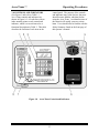
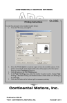
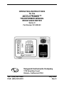
3.0 CONTROLS AND INDICATORS
(See Figure 1 and refer to Table 1.)
Accu-Trans controls and indicators are
shown in Figure 1.0. A leader line with an
index number points to each control and
indicator, which is cross-referenced to a
functional description in Table 2. This table
describes the function of each item on the
Figure 1.0
control-panel. The purpose of the controls
and indicators may seem obvious, but users
should become familiar with them before
using the Accu-Trans. Accidental misuse of
the controls will usually cause no serious
harm. Users should also be familiar with the
Safety Summary found on the front page of
this operator’s manual.
Accu-Trans Controls and Indicators
5
Accu-Trans
Table 1.0
Fig. 1
Index
1
Operating Procedures
Functional Descriptions of Accu-Trans Controls and Indicators
Panel Markings
RS-232C
2
(Not titled; 16-key pad)
3
(Not titled; LCD)
4
120/240 2A, 50-60 Hz
Fuse: 250 Vac, 3A Slow Blow
5
GROUND
6
(Not titled; thermal printer)
7
HIGH CURRENT
PRESENT
8
(Not titled; test lead jacks)
Functional Descriptions
Computer interface port; 9-pin connector;
female DB type.The data are set to 19,200
baud, 1 start bit, 2 stop bits, 8 data bits, and no
parity bit.
PIN
SIGNAL
2
Rx
3
Tx
5
Signal Gnd
Pushbutton operating controls; 10 key pad, plus
START, STOP, ENTER, CLEAR, two paperdrive buttons; number keys 2 thru 9 have dual
functions as letter entries (a la telephone dialer
key pad).
Liquid-Crystal Display, 4-line by 20 character;
back lighted and readable in sunlight; Displays
menus, user selections, status readouts, and test
results.
Input power connector with third-wire safety
ground, ON (1)/OFF (0) rocker toggle switch;
has built-in fuse protection.
Stud, 5/16-18 thread, with hand-turned wing
nut; Safety Ground; This must be connected to
station ground before connecting cables to
transformer and begin testing.
Built in thermal printer; prints test results in the
field on 2.5-inch-wide paper. NOTE: For best
high-contrast print quality, it is recommended
that only VIC thermal paper be used.
LED indicator light, red; When lighted, this
indicator warns operators that there is a
possibility that lethal high voltage will exist if
any test lead is disconnected while current is
running through an inductive load. Failure to
heed this warning can result in shock and/or
fatal injury to personnel.
Test connector jacks, female; for connecting
heavy gauge current leads and voltage-sensing
test leads. Plug-in voltage plugs are not polarity
sensitive, but must be plugged into the jacks
adjacent to their companion current jacks.
6
Accu-Trans
Operating Procedures
4.0 PRETEST SETUP
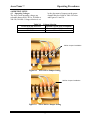
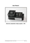
4.1 Operating Voltages
The Accu-Trans operating voltages are
selectable between 90-130Vac, 50/60Hz or
200-240, 50/60Hz. Voltage selection is set
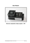
Table 2.0
VOLTAGE SELECTION
90-130Vac
200-240Vac
by the placement of jumpers on the power
terminal block as listed in Table 2.0 below
and Figures 2.0 and 3.0 .
Voltage Selection
TERMINAL BLOCK JUMPERS
Brown to Blue & Yellow to Green
Blue to Yellow
120Vac Jumper Installation
Figure 2.0
90 to 130Vac Jumper Setting
220Vac Jumper Installation
Figure 3.0
210 to 240Vac Jumper Setting
7
Accu-Trans
Operating Procedures
4.2 Accu-Trans LCD Contrast Control
To darken the LCD display, press and hold
the “Paper ∧ Contrast” switch for two
seconds; to lighten the LCD display, press
and hold the “Paper ∨ Contrast” switch for
two seconds.
Figure 1.0 to become familiar with the total
Accu-Trans operation and the logical
branching for various test options. (More
experienced operators may use this figure as
a handy help and reference guide.
WARNING
Do not touch or disconnect any test lead
that is connected to a transformer
terminal while high current is being
conducted during any test. Failure to
heed this warning can result in lethal
electrical shock to personnel and/or
damage to equipment.
4.3 Accu-Trans Printer Paper Control
To advance the Accu-Trans printer paper,
press and release the “Paper ∧ Contrast”
switch.
To retract the Accu-Trans printer paper,
press and release the “Paper ∨ Contrast”
switch.
6.1 General Procedures
a) Ground Accu-Trans to substation ground
(item 5 in Figure 1.0).
b) Plug Accu-Trans power cable into a
power outlet.
c) Insert current-cable plugs and voltagesensing cable plugs into respective controlpanel jacks (index 8 of Figure 1.0). Ensure
that voltage plugs are plugged into jacks that
are adjacent to companion current jacks.
5.0 ACCU-TRANS PRINTER PAPER
The Accu-Trans built-in thermal printer uses
2.5-inch wide thermal paper for printing test
results. To maintain the highest quality testresult printing and to avoid paper jamming,
the use of paper supplied by our factory is
highly recommended. Additional paper can
be ordered from either of the two sources
listed below:
Vanguard Instruments Co, Inc.
1710 Grevillea Court
Ontario, CA 91761
Tel: 909-923-9390
Fax: 909-923-9391
Part Number: TP-3 Paper
OR
BG Instrument Co.
13607 E. Trent Avenue
Spokane, WA 99216
Tel: 509-893-9881
Fax: 509-893-9803
Part Number: TP-3 paper
d) Attach test-cable clamps to transformer
terminals of winding that is to be measured
(or if load is not an inductance, simply
attach test leads to opposite terminals of the
resistive load).
e) Turn on Accu-Trans power (item 4 in
Figure 1) by pressing “I” on rocker switch.
f) Observe that after configuration data is
displayed briefly, then the start-up menu
displays (with selection options for “1. RUN
TEST,” “2. SETUP”).
6.0 OPERATING PROCEDURES
Before using the Accu-Trans for measuring
any resistance, operators should review the
Summary of Step-by-Step Operation of the
Accu-Trans found in Figure 4.0. AccuTrans operations are simple, requiring the
selection of choices from the display menus
and responding to the displayed prompts.
However, first-time operators should review
8
Accu-Trans
Figure 4.0
Operating Procedures
Summary of Step-by-Step Accu-Trans Operation
9
Accu-Trans
Operating Procedures
6.2 Step-by-Step Procedures at StartUp Menu
This display doesn’t prompt any action; but
simply reminds the user that a test is in
progress. The time for this display depends
on size of the winding’s inductance and the
test mode selected.
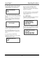
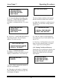
6.2.1 START-UP Menu:
Observe that the Start-Up menu displays as
shown below:
1. TEST XFMR
2. SETUP
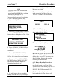
The Accu-Trans determines when the
resistance reading is stable and shows
resistance value on LCD as follows:
04/15/01
09:28:03
MEASURED RESISTANCE
“STOP” TO ACCEPT
a) Press key #1 to start test. Press #2 to
select other options (i.e. enter recordidentification data, recall test results, etc.)
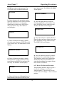
6.2.2 Test Transformer Procedure
The following procedure shows the steps to
get a resistance reading from a device under
test.
a) To start a test, press key #1 (TEST
XFMR) from main menu. When the test
mode is selected, a “WARNING!” display is
shown below:
120.0 MICRO-OHM
The Accu-Trans continues to apply the test
voltage on the transformer’s winding and
updates the resistance value on the display.
d) The user presses STOP key to retain this
data and go to the next step. (If the displayed
data is not O.K., press CLEAR to return to
the Start-Up Menu.)
**********WARNING!**********
DANGEROUS FLASH-OVER
MAY OCCUR IF CABLES
ARE DISCONNECTED!
MEASURED RESISTANCE
FINAL RESISTANCE
120.0 MICRO-OHM
This warning reminds operators that the next
sequence of test steps will run current
through the load, which, if inductive, will
cause lethal voltages to be generated if the
cables are disconnected before the current is
ramped down to zero.
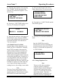
e) Press ENTER key and go to the next
step. The print-option menu is now
displayed.
PRINT TEST RESULTS
1. YES
2. NO
b) Press the ENTER key and proceed to the
next step. The start test display appears:
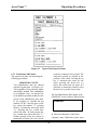
f) Press key #1 to print test results. Typical
Accu-Trans test report is shown in figure 5.
c) Press the START key to Start test. The
test-in progress display appears below:
g) Select key #2 to bypass printing results.
TEST IN PROGRESS
PLEASE WAIT………
* XFMR CHARGING*
10
Accu-Trans
Operating Procedures
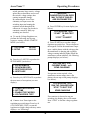
h) When either option is selected, the next
window displays with the prompt “KEEP
THIS READING? Go to the next step.
m) At the “RUN ANOTHER TEST?”
Menu, the operator may choose to run
another test, by selecting “YES”. Return to
step 6.2.2.a to run test.
KEEP THIS READING
1.YES
2. NO
n) If NO is selected (i.e., don’t run another
test) the program returns to the Start-Up.
Menu (section 6.2.1).
i) If the KEEP THIS READING prompt is
answered with a YES, the following display
appears.
j) Go to step l. If NO is selected, the next
display is skipped and the second display
following appears.
6.3 SETUP Menu:
This menu is displayed by again selecting 2
(SETUP) on the Start-UP MENU
1. ENTER XFMR DATA
2. REVIEW RECORD
3. RESTORE RECORD
4. NEXT PAGE
TEST SAVED
a) Select key 1 to 4. When key #4 (NEXT
PAGE) is selected, More choices for setup
menu are shown (below).
The TEST SAVED display advises that the
resistance measurement has been saved.
k) Press ENTER and go to the next step.
“RUN ANOTHER TEST?” message will
appears.
1. COMPUTER CONTROL
2. SET TIME
3. ENABLE TEST MODE
4. VOLTAGE REG. TEST
l) Select NO from “KEEP THIS
RESULTS” will take the user to the “RUN
ANOTHER TEST?” menu.
RUN ANOTHER TEST?
1. YES
2. NO
11
Accu-Trans
Operating Procedures
Figure 5.0
Typical Test Report Printout
6.3.1 Transformer ID Entries:
The operator can enter test data using the
following procedures.
as the key continues to be pressed. The
characters selected are entered at the
position of the cursor. Pressing the up
key (∧) advances the cursor by one
space; pressing the down key (∨)
moves the cursor back one space. If a
character is erroneously entered, select
the new key to get the correct entry.
OPERATOR’S NOTE
Test Identification data are entered
with the keypad (item 2 of Figure 1.0).
The keypad has 10 keys that are alphanumerically marked, like pushbuttons
on a telephone. Keys are pressed for
each character position (marked by the
cursor) in the identification area; thus:
If, for example, we consider the key
marked 2/A B C, the first press of the
key selects the number “2,” pressing
the key a second time selects the letter
“A,” pressing the key a third time
selects the letter “B, and pressing the
key a fourth time selects the letter “C.”
Further pressing of the key returns to
the number selection; the cycle repeats
The first Identification (ID) display is the
COMPANY screen, which is shown below:
COMPANY:
a) Enter the characters of the utility
company’s name. When this is done, press
12
Accu-Trans
Operating Procedures
ENTER key and go to the next step. The
STATION screen will then be displayed.
go to the next step. The SERIAL NUMBER
screen displays.
STATION:
SERIAL NUMBER:
b) Enter characters for naming the station
where the transformer to be tested is located.
When all the characters are selected or
identifying the station, press ENTER key
and go to the next step. The CIRCUIT
screen displays.
f) Enter the alpha-numeric characters
needed to identify the serial number, then
press ENTER key and go to the next step.
The KVA RATING screen displays.
KVA RATING:
CIRCUIT:
g) Enter the numbers to identify the KVA
rating for the transformer being tested, then
press ENTER key and go to the next step.
The OPERTOR screen displays.
c) Enter all characters needed to identify
the circuit name, then press ENTER key and
go to the next step. The manufacturer screen
displays.
OPERATOR:
MANUFACTURER:
h) Enter the characters needed to identify
the operator who is performing the tests.
This completes entries for the transformer
identification data. Press ENTER key to
enter the selected data: the program returns
to the START-UP MENU.
d) Enter all characters needed to identify
the manufacturer of the transformer being
tested, then press ENTER key and go to the
next step. The MODEL screen displays.
6.3.2 Review Test Records Procedure
This procedure describes steps to review a
test record residing in Accu-Trans
working memory. The user can view the
record on the LCD display or from a thermal
printout.
MODEL:
e) Enter the characters of the transformer’s
model number, then press ENTER key and
13
Accu-Trans
Operating Procedures
press the down (∨) key to roll down, through
the saved test records.
NOTE
To review a test record stored in Flash
EEPROM, the user must first restore test
record from Flash EEPROM to working
memory (see paragraph 6.3.3).
The next menu displays the number of test.
in the record, time and date of the test.
There are 2 tests in the test record below.
These procedural steps begin by selecting
SETUP on the Start-Up Menu, which
displays the Set-Up Menu, shown below:
2 TESTS
06/12/01
1. ENTER XFMR ID
2. REVIEW RECORD
3. RESTORE RECORD
4. NEXT PAGE
12:21:34
f) Press the UP (∧) key to review the
resistance measured in the first test, which
show in the following display.
a) In the Set-Up Menu (see above), press 2
to select the REVIEW RECORD procedure.
It starts with the display shown below. Go to
the next step.
TEST NUMBER: 1
ACTIVE TEST
10.88 OHM
AT 0.824 Amps
REVIEW RECORD
1. SCROLL TEST RECORD
2. PRINT TEST RECORD
g) Press the UP (∧) key again to display the
second test on the record as shown below:
TEST NUMBER: 2
ACTIVE TEST
122.8 MILLI-OHMs
AT 2.000 Amps
b) Press 1 (SCROLL TEST RECORD) to
view all the test records in memory (see
menu above).
c) Press 2 (PRINT TEST RECORDS) to
output test record to the thermal printer.
See Fig. 5.0 for typical test record printout.
h) When the operator has reviewed the test
measurement for the selected record in the
display above, press STOP to return to the
Start-Up Menu. This ends the steps for
reviewing saved test records.
d) Pressing the 1 key (SCROLL TEST
RECORD) produces the RECORD “ID”
INFO display. This menu displays the
information related to the test.
6.3.3 Restore Recording Procedures
This procedure allows the user to restore a
test record from the Accu-Trans Flash
EEPROM to working memory. The user can
then review the test record using the
REVIEW RECORD command (6.3.2).
RECORD “ID” INFO:
The Restore Recording Procedure steps
begin at the Set-Up Menu, shown next:
e) To scroll through the test records in
memory, press the UP (∧) key to roll up or
14
Accu-Trans
Operating Procedures
RECORD RESTORED!
1. ENTER XFMR ID
2. REVIEW RECORD
3. RESTORE RECORD
4. NEXT PAGE
a) To begin the Restore Recording steps,
press key # 3 (RESTORE RECORDING),
which shows a menu for three main
procedures, as displayed below. Go to next
step.
The above display confirms to the operator
that the selected record has been restored.
e) When the restoration is confirmed, press
ENTER key to select the viewing option as
shown below.
1. RESTORE RECORD
2. DIRECTORY
3. ERASE RECORDS
4. NEXT PAGE
REVIEW RECORD
1. SCROLL TEST RECORD
2. PRINT TEST RECORD
b) Press key # 1 (RESTORE RECORD) to
begin the procedure. The next display
appears. Go to the next step.
f) If the user wants to scroll through the
test record, press key #1 and continue from
step 6.3.2.b.
RESTORE RECORD
i) Press key # 2 will produce a test record
print out on the thermal printer. See figure
5.0 for a typical test record printout.
1. ENTER RECORD NUMBER
2. SCROLL TO SELECT
6.3.4 Printing Test-Record Directory
Printing the test record directory begins with
the Set-Up Menu shown below (the same
display from which the Review Records
steps began):
c) Press # 1 (ENTER RECORD
NUMBER) to produce the Restore Record
display, as shown below. Go to next step.
1. ENTER XFMR ID
2. PREVIEW RECORD
3. RESTORE RECORD
4. NEXT PAGE
RESTORE RECORD
NUMBER:
The above display prompts the operator to
enter the record number.
d) When the record number is displayed,
press ENTER and go to the next step. The
next display will appear.
15
Accu-Trans
Operating Procedures
a) Press key # 3 to select the Restore
Recording step sequence, and go to the next
step. The following menu displays:
c) Press key # 1 to print the entire directory
of test records; Press key # 2 to print the
short directory.
A short directory lists the last 20 test records
stored in the Accu-Trans memory.
This ends the print directory sequence.
1. RESTORE RECORD
2. DIRECTORY
3. ERASE RECORD
b) Press key # 2 (DIRECTORY) and go to
the next step. The menu below displays:
PRINT DIRECTORY
1. FULL DIRECTORY
2. SHORT DIRECTORY
16
Accu-Trans
Operating Procedures
Figure 6.0
Typical Record Directory Printout
6.3.5. Erase Recording Procedure
The Erase Recording sequence begins with
the Set-Up Menu, shown below. Go to the
next step.
ERASE RECORD
1. ERASE SINGLE REC.
2. ERASE ALL RECORDS
1. ENTER XFMR ID
2. PREVIEW RECORD
3. RESTORE RECORD
4. NEXT PAGE
c) To erase a single a record, press key # 1;
to erase all records press key # 2. If a single
recording is selected go to the next step; The
prompt below displays. To erase all
recordings go to step f.
a) Press # 3 (RESTORE RECORD) and go
to the next step. The display below appears.
1. RESTORE RECORD
2. DIRECTORY
3. ERASE RECORD
ERASE RECORD
NUMBER:
b) Press # 3 (ERASE RECORD) and go to
next display.
17
Accu-Trans
Operating Procedures
d) Enter the number of the record that is to
be erased and press ENTER key. Go to the
next step. The confirmation display appears
as shown below:
6.3.6 Enabling Computer Interface
The Computer Interface Mode allows the
user to retrieve test records stored in the
Acccu-Trans memory via the RS-232C port
An IBM PC program is provided with each
Accu-Trans allowing the user using his PC
to retrieve these test records.
RECORD NUMBER
ERASED
a) This procedure begins in the Set-Up
Menu, shown below. Go to the next step:
1. ENTER XFMR ID
2. REVIEW RECORD
3. RESTORE RECORD
4. NEXT PAGE
e) When the erased record number is
confirmed, press ENTER key to return to the
start-Up Menu ending the sequence for
erasing a single record.
f) When key # 2 (ERASE ALL
RECORDS) is pressed in the Erase Record
display (back in step c, the following prompt
displays. Go to the next step.
b) Pressing key #4 (NEXT PAGE) and the
menu below appears. Go to the next step.
1. COMPUTER CONTROL
2. SET TIME
3. ENABLE TEST MODES
ERASE ALL RECORDS!
ARE YOU SURE?
“ENTER” TO CONTINUE
c) Press key # 1 (COMPUTER
CONTROL) and go to the next step. The
display below appears:
g) Press ENTER key to erase all test
records. If ERASE ALL RECORDS was
mistakenly selected, press “STOP” to abort
the erase process and return to the Start-Up
menu. When ENTER key is pressed, the
following confirmation message is
displayed. Press ENTER key to return to the
Start-Up Menue:
COMPUTER ITF MODE
j) Pressing the STOP key terminates the
computer control, at which time the Start-Up
Menu displays, ending this step sequence.
RECORD ERASED!
6.3.7 Setting Date and Time
The date and time set begins at the Set-Up
Menu, shown below:
1. ENTER XFMR ID
2. REVIEW RECORD
3. RESTORE RECORD
4. NEXT PAGE
This ends the Erase Record(s) sequence.
18
Accu-Trans
Operating Procedures
a) Begin the date and time set by pressing
key # 4 (NEXT PAGE) and going to the
next step. The menu below appears. Go to
the next step.
a) This procedure begins in the Set-Up
Menu, shown below. Go to the next step:
1. ENTER XFMR ID
2. REVIEW RECORD
3. RESTORE RECORD
4. NEXT PAGE
1. COMPUTER CONTROL
2. SET TIME
3. ENABLE TEST MODE
b) Pressing key #4 (NEXT PAGE) and the
menu below appears:
b) Press key # 2 (SET TIME) and go to the
next step. The display below appears:
ENTER
MM-DD-YY
1. COMPUTER CONTROL
2. SET TIME
3. ENABLE TEST MODES
HH:MM:SS
c) Enter the date and time, which appear in
the dashed-line areas, then press ENTER
key to set the calendar and clock and return
to the Start-UP Menu. This ends the Set
Time step sequence.
c) Press key #3 to activate PASSIVE Test
mode.
Note
Once the PASSIVE test mode is
selected, the Accu-Trans will display the
test mode selection menu (shown below)
in step 6.2.2.a after the user presses key
#1 (TEST XFMR).
6.3.8 Enable Passive Test Mode
Operators have a choice between two test
modes: ACTIVE or PASSIVE. Normally,
the ACTIVE test mode is best suited for
quickly testing transformer resistances. In
this mode, the Accu-Trans automatically
ramps the test current up to its final test
value (when the magnetic field is saturated)
in the shortest possible time. However, in a
very large inductive load, the ACTIVE test
mode reading may appear to be unstable.
In this situation, the user may want to try the
PASSIVE test mode test. In this mode, the
Accu-Trans will take longer to provide a
reading, however, the reading is more stable.
1. ACTIVE TEST
2. PASSIVE TEST
6.3.9 Voltage Regulator Test
Note
This test verifies that a regulating
switch in a primary-voltage tap
regulator changes contacts through its
selection range with no break in the
circuit (i.e., it checks the tap switch’s
make-before-break). This test is
important because, in actual use, any
breaks in current in a regulating tap
Note
The Accu-Trans always defaults to the
ACTIVE test mode when power is first
applied to the unit. The user needs to enable
the PASSIVE test mode before using it.
19
Accu-Trans
Operating Procedures
switch generates large reactive voltage
spikes that are hazardous and exceed
the switch’s voltage ratings, thus
causing irreparable damage.
By connecting the Accu-Trans
continuity test input across the
switching input and running the
regulator switch through all the
contacts in it’s range, any breaks in
continuity caused by faulty tap
switching are detected.
*****WARNING!*****
DANGEROUS FLASH-OVER
MAY OCCUR IF CABLES
ARE DISCONNECTED!
e) Press ENTER key for next display (see
below):
VOLTAGE REG. TEST
“START” TO RUN TEST
or
“STOP” TO ABORT
a) To run the Voltage-Regulator test,
perform the following step-by-step
sequence, starting with the STARTUP
MENU (see below):
1. TEST XFMR
2. SETUP
f) Press START key to run the voltage
regulator tap-switch test. The test begins as
the magnetic field in the transformer ramps
up to a stable plateau with the advisory that
the transformer is charging (the red Highvoltage warning indicator lights) When the
transformer current stabilizes, the following
prompt displays (see below):
08/14/01
12:21:01
b) Press key #2 (SETUP) to produce the
SETUP MENU (see below):
VOLTAGE REG. TEST
CURRENT RAMP: xx %
*XFMR CHARGING*
1. ENTER XFMR ID
2. REVIEW RECORD
3. RESTORE RECORD
4. NEXT PAGE
No operator action required; when
transformer current ramps nears a flat
plateau, the run tap switch prompt displays
(see below):
c) Press key #4 (NEXT PAGE) to produce
the next menu of test options (see next
display):
VOLTAGE REG. TEST
RUN TAP CHANGER NOW
“STOP” TO EXIT TEST
XFMR CHARGING
1. COMPUTER CONTROL
2. SET TIME
3. ENABLE TEST MODES
4. VOLTAGE REG. TEST
If no transient is detected as taps are
switching, the display above will remain.
Press “STOP” to end the voltage regulator
test.
d) Connect Accu-Trans input to the
regulating tap-switch input. Press key #4
(VOLTAGE REG. TEST) to start the
regulator test (high-voltage advisory notice
displays—see following):
20
Accu-Trans
Operating Procedures
If a switch break is detected, an advisory
displays (shown below). Press STOP to end
the voltage-regulator test.
TRANSIENT DETECTED!
.
21
Accu-Trans
Operating Procedures
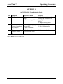
APPENDIX A
ACCU-TRANS Troubleshooting Guide
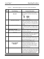
Item Symptom
1
Reading is incorrect.
Possible Problem
1. Poor connection at the
Clips.
2. Broken sensing lead.
2
1. No test current going
through DUT.
2. Drive circuit not
working.
1. Broken sense leads.
2. Reverse sense leads.
3
No Test Current.
(Current % read zero)
and resistance
reading=0
Have test current but
resistance reading =
0.
NOTE: DUT=Device Under Test
Solution
1.Check connection to make sure
sensing and current teeth are
touching the device under test
(DUT).
2. Inspect sensing cables.
1. Check Connection to DUT.
2. Run Calibration Test.
1. Inspect sense leads.
1710 Grevillea Court, Ontario, CA 91761, USA
Phone: 909-923-9390
Fax: 909-923-9391
Website: http//www.vanguard-instruments.com
ACCU-TRANS 09/09/01: OAK