1
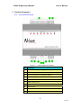
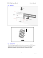
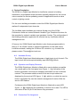
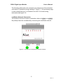
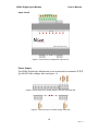
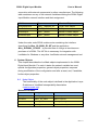
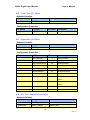
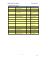
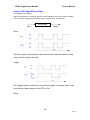
2208L Digital Input Module
User’s Manual
2208L Digital Input Module
Revision 1.0
Nico Technology Ltd.
24F,No.37,SanMin Rd, 2.Sec, PanChiao City, Taipei County, Taiwan
Phone
+886-2-2954-5338
Fax
+886-2-2954-5308
Product Info
[email protected]
Technical Support
[email protected]
Web site
http://www.nico-tech.com
1
Rev.1.0
2208L Digital Input Module
User’s Manual
This Manual
This manual provides any required information for installation, configuration
and operation of the Nico Technology Ltd. 2208L Digital Input Module.
It exclusively treats the handling of this device. It neither describes the
LonWorks technology by Echelon nor the LonMark profile implemented in
detail. More specific information concerning these subjects can be found in the
documentation of Echelon (www.echelon.com) and the LonMark
Interoperability Association (www.lonmark.org).
The first part of this manual provides a survey about the device and its
installation in chapters 1 to 3. The 2nd part describes the implemented
application for lighting control and its configuration possibilities. Chapter 4
contains a description of the firmware interface while chapter 5 describes the
implemented LonMark Objects in detail providing an outlook of the individual
objects, their tasks and their relevant configuration parameters.
Chapter 6 explains the basics required to connect the objects to each other.
This manual is relevant for all variants of the Nico Technology Ltd. 2208L
Digital Input Module where applications for building automation control are
implemented.
This documentation is subject to modification at any time without prior advice. Nico does not take over any
responsibility for mistakes or inaccuracies in this documentation and eventually occurring consequences.
In any case Nico as well as its representatives and staff are not reliable for eventual defaults, damages caused
indirectly or during use, occurring due to the use or non-usability of the software or the accompanying documentation.
Nico is a registered trademark of Nico Technology Ltd.
Echelon, LON, LonMark, LonWorks and Neuron are registered trademarks of Echelon Corporation. Other name may
be registered trade marks of the respective companies.
2
Rev.1.0
2208L Digital Input Module
User’s Manual
Contents
Contents ..........................................................................................................3
2 Product Information ..................................................................................4
3
2.1
Functional Elements.......................................................................4
Installation.................................................................................................5
4
3.1
Warnings ........................................................................................5
3.2
Mounting ........................................................................................6
3.3
Connections ...................................................................................6
3.4
Software Installation.......................................................................7
Device Description....................................................................................8
4.1
4.2
4.3
Hardware Survey ...........................................................................8
Operation and Display Elements....................................................8
Connection Pin Assignment ...........................................................8
5
4.4
Wiring Diagram ............................................................................ 11
4.5
EMC .............................................................................................12
4.6
Technical Specifications ...............................................................13
4.7
Dimensions ..................................................................................13
Application Software for Building Automation Control.............................14
6
5.1
System Scope..............................................................................14
5.2
Interoperable Interface .................................................................14
System Objects.......................................................................................15
6.1
6.2
6.3
6.4
Node Object .................................................................................15
Local Clock (LC) Object ...............................................................16
Digital Input (DI) Object................................................................16
Nico Tech. Switch Process Object................................................16
3
Rev.1.0
2208L Digital Input Module
User’s Manual
2 Product Information
2.1 Functional Elements
Figure 1.1 2208L Digital Input Module
No
1
2,3
Description
Input channels for 24VDC@100mA
24VDC Input power
4
T1,T2 for Connect to LonWorks network
5
24VDC Input power
6
T1,T2 for Connect to LonWorks network
7
24VDC Input power
8
Service Pin button
9
Reset button
A
Service Pin LED indicator
B
Reset LED indicator
4
Rev.1.0
2208L Digital Input Module
User’s Manual
3 Installation
This chapter first describes the installation of the device; the installation of the
configuration software is described in section 3.4.
3.1
Warnings
Attention
The device must be installed in compliance with the relevant DIN/VDE
regulations or the relevant national standards. The connection to the
supply voltage must be performed in accordance with VDE 0100 and VDE
0160 or the relevant national standards. Installation should perform by
qualified and technical experienced personnel only.
CAUTION
At the connections of the input channels 1 – 4 (Fig. 1.1, terminal 1) and the
power supply (terminals 2, 3, 5, 7) 24VDC main voltage with load guard
band is accessible. The installation of the unit therefore has to be effected
in a switch cabinet or behind a respective cover.
5
Rev.1.0
2208L Digital Input Module
3.2
User’s Manual
Mounting
3.3 Connections
The 2208L Digital Input Module has to be connected to a 24VDC power
supply and to the LonWorks network. According to the respective
application peripheral equipment has to be connected to inputs.
6
Rev.1.0
2208L Digital Input Module
User’s Manual
Attention
Before connecting peripheral equipment the power supply device has to be
switched off.
The connection is effected by means of the included plug-screw terminals.
Clamping range of the plug-screw terminals:
- DC power and network connections (terminals 2 , 3 , 4 , 5 , 6 , 7): 3.0 mm
- Low voltage connections (terminals 1): 2.4 mm
The pin assignment of the connections is described in chapter 3.1, also
containing wiring details.
Voltage
The 24 Volt Direct Current connections are through connected in order to
achieve easy wiring.
LonWorks Network
The connection to the LonWorks network is made by means of twisted-pair
cables. The connection “shield” has to be connected to ground in order to
achieve a reliable dissipation of over-voltage on the LON circuits.
Digital Inputs
The actors to be controlled are connected to the DC outputs. In each case the
connection is effected terminal 1).
Attention
The 2108L input power supply must be 24VDC power supply only.
3.4 Software Installation
The configuration software of the 2208L Digital Input Module has to be
installed by starting the program Setup.exe on the data carrier provided. It
suns under Windows 9x/2000 and NT.
Download url: http://www.nico-tech.com/download
7
Rev.1.0
2208L Digital Input Module
User’s Manual
4 Device Description
The 2208L is a Digital Input Module for LonWorks network in building
automation. Its peripheral scope has been specially designed for the use as
valve controller for device spreading control of applications such as valve
control or lighting control.
For the use in building automation control the 2208L Digital Input Module
realizes 8 independent input channels.
The LonMark object available per channel flexible use of the 2108L;
Furthermore there are several Network Variable Type Translator functions for
the operation by network variable type translator function. The configuration of
the building automation application is effected via any LonWorks network
management tool.
Of course, the 2208L Digital Input Module is also freeing programmable in
Neuron C. As a flash module is used the application can be load via the
LonWorks network, making the 2108L an I/O controller, e.g. for detail info
please contact: [email protected]
4.1 Hardware Survey
The 2208L Digital Input Module disposes of eight input circuit for each. The
input circuit can be accept individually input 24VDC@100mA
4.2 Operation and Display Elements
The 2208L Digital Input Module is fitted with a service button accessible
via a small gap on the front panel (see Figure. 1.1, 8). Activation of the
buttons generates a service-pin message transmitted via the LonWorks
network. The processor status as well as the service-pin status are
displayed by the service LED (figure. 1.1,A), which is on while the service
button is activated. By use the network management function Wink the
service LED flashes.
Furthermore the 2208L Digital Input Module is fitted with a reset LED
(figure. 1.1, B), displaying the availability of device occur reset. The LED is
connection to an I/O pin of the Neuron chip processor.
4.3
Connection Pin Assignment
8
Rev.1.0
2208L Digital Input Module
User’s Manual
The following tables show the connector pin assignment of the individual
connectors. Connections the 1 marking cf. Figure. 1.1 On previously page.
In each clamp block pin 1 is situated on the left. For further wiring
information see figure 3.2.
LonWorks Network Connection
The double-core bus line can be connection either to LON A or to LON B.
No polarity has to be considered by connecting the LonWorks network.
Figure 3.1 Connector pin assignment LonWorks network
9
Rev.1.0
2208L Digital Input Module
User’s Manual
Input circuit
Figure 3.2 Connector pin assignment input circuit.
Power Supply
The 2208L Digital Input Module has to be connected via connector 2, 3, 5,
7 to 24VDC main voltage. Also see figure. 1.1.
Figure 3.3 Connector pin for Power Supply near input channels side
Figure 3.4 Connector pin for Power Supply other side
10
Rev.1.0
2208L Digital Input Module
4.4
User’s Manual
Wiring Diagram
Figure 3.5 Connecting to 2208L
Figure 3.6 Connecting to other one of 2208L or LonWorks device
11
Rev.1.0
2208L Digital Input Module
User’s Manual
4.5 EMC
The 2208L Digital Input Module is a CE certified device according to the
regulation 89/336/EEC for electron magnetic compatibility, modified by
92/31/EEC”. Concerning the emission it fulfills classification B (living area)
according to EN 55022A/B, EN 55011 A/B and EN 50081-1/2 and,
concerning the interference sensibility, classification A (industrial area)
according to EN 50082-2.
12
Rev.1.0
2208L Digital Input Module
4.6
User’s Manual
Technical Specifications
CPU
Echelon Neuron 3150,10MHz
Memory
64Kbytes Flash memory, 512Bytes EEPROM,2Kbytes
SRAM,8Kbyte external SRAM
LonWorks Transceiver
FTT-10A/FT-X1
Power supply
24VDC
Power consumption
100mA(Per channel maximum)
Connection
Plug-screw clamp 2.5mm for input channels, 3.0mm for
DC power supply and LonWorks network communication
port.
Temperature
Operation
Storage
0 ~ +50
-20 ~ +70
Admitted relative humidity
5 ~ 93%, non condensing
Dimensions
135 x 120 x 55 mm,
DIN 43880, incl. clamps
Mounting
DIN rail(EN 50022, 35 x 15)
Display & Operation
Service-pin and Reset LED indicator and button
I/O Channels
8 digital input channels with indicator.
Table 3.1 Technical Specification
4.7
Dimensions
Figure 3.5 Device dimensions without plug-screw clamps
13
Rev.1.0
2208L Digital Input Module
User’s Manual
5 Application Software for Building Automation Control
On the 2208L Digital Input Module an application for building automation
control is implemented, making input functionality as well as digital control
functions available.
Therefore the relevant LonMark profiles stated in Table 4.1 are implemented.
The use of network variables (NV) compiles with the LonMark standard.
SCPT’s are used for parameterization by applying the read/write-memory
method.
Title
Present
Version
Identification
LonMark Application Layer Interoperability
Guidelines
V3.1
078-0120-01D
The SNVT Master List and Programmer’s
Guide
V 8.0
The SCPT Master List
V 8.0
Local Clock Functional Profile
LonMark Functional Profile Open Loop Sensor V 1.0
001
Signal Input Switch Process Object
Table 4.1 Referring document about LonMark profiles
5.1 System Scope
The 2208L Digital Input Module is equipped with eight channels for Digital
Input.
The digital inputs of the 2208L Digital Input Module allow the connection of
actuator. A Digital Input (DI) object, according to LonMark Standard can be
assigned to these input and configured.
Furthermore the 2208L can act as constant sensor collector. The sensor
collector either generated by the internal DI object; via an output network
variable.
The 2108L is equipped with eight digital input circuits to connect e.g.
Motion sensor,.
5.2 Interoperable Interface
The LonMark profile 001 is realized in the 2208L Digital Input Module. The
network interface remains standardized, clear and especially it is
interoperable. That means, the 2208L Digital Input Module can be used in
14
Rev.1.0
2208L Digital Input Module
User’s Manual
connection with network components by other manufactures. The following
table contains a survey of the network variables defining the 2208L Digital
Input Module network interface and their assignment.
NV Name
Type
Allocated Object
nvoLocalClock
SNVT_elapsed_tm
Local Clock Object
nvoSwitch
SNVT_switch
DI Object
nviSwInput
SNVT_switch
Switch Process Object
nvoSwOutput
SNVT_switch
Switch Process Object
Table 4.4 Allocation of NVs and LonMark objects
Under the order code 2208L a data carrier containing the interface
describing file Nico_DI-2208L_R1.XIF and the application
Nico_DI-2208L_R1.APB is provided free of charge at simultaneous
purchase of a 2208L. The XIF-file is necessary for integration with
LonMaker for Windows or any other LonWorks network management tool.
6 System Objects
This chapter describes the LonMark objects implemented in the 2208L
Digital Input Module. For each it states the network variable les used,
special configuration properties, general object properties, response
during modification of the configuration and after a reset, and, if available,
further object properties.
6.1
Node Object
The functionality of the node object is defined in the Application Layer
Guidelines of LonMark Interoperability Association
(www.lonmark.org).
Network Variables
NV Name
NV Type
Comment
nviRequest
SNVT_obj_request
Status request
nvoStatus
SNVT_obj_status
Status response
nvoAlarm
SNVT_alarm
Alarm generating
nvoFileDirectory
SNVT_address
Address of file for parameterization
15
Rev.1.0
2208L Digital Input Module
6.2
User’s Manual
Local Clock (LC) Object
Network Variables
NV Name
NV Type
Comment
nvoLocalClock
SNVT_elasped_tm
Run period time
Configuration Properties
CP Name
CP Type
CP Index
UCPTclockCalibrate
6.3
16
Comment
Clock Calibrate
Digital Input (DI) Object
Network Variables
NV Name
NV Type
Comment
nvoSwitch
SNVT_switch
I/O status of DI Object
Configuration Properties
CP Name
CP Type
CP Index
Comment
SCPTdefOutput
7
Default Output
SCPTinvrtOutput
16
Invert input of nviSwitch
SCPTmaxSendTime
49
Send heartbeat
SCPTminSendTime
52
Send throttle
SCPTdebounce
139
Debouncing time
SCPTovrBehave
32
Override behavior
SCPTovrValue
33
Override value
SCPTobjMajVer
167
Read only; Must read from
device
SCPTobjMinVer
168
Read only; Must read from
device
6.4
SCPTlocation
17
Location label
SCPTmaxRcvTime
48
Receive heartbeat
Nico Tech. Switch Process Object
Network Variables
NV Name
NV Type
Comment
nviSwInput
SNVT_switch
Switch input
nvoSwOutput
SNVT_switch
Switch output
16
Rev.1.0
2208L Digital Input Module
User’s Manual
Configuration Properties
CP Name
CP Type
CP Index Comment
SCPTinvrtOutput
16
Invert Input of value
SCPTdebounce
139
Debounceing time
UCPTdigitalOProcessType
4
Process type
UCPTactiveSw
8
Output value for ON
state
SCPTdefOutput
7
Default output
SCPTmaxSendTime
49
Send heartbeat
UCPTinactiveSw
9
Output value for OFF
state
SCPTlocation
17
Location label
SCPTobjMajVer
167
Read only; Must read
from device
SCPTobjMinVer
168
Read only; Must read
from device
SCPToffDely
30
Turn off delay
UCPTonDely
1
Turn on delay
SCPTovrBehave
32
Override Behavior
SCPTovrValue
33
Override Value
UCPTpulseWidth
12
Pulse width
SCPTminSendTime
52
Send throttle
17
Rev.1.0
2208L Digital Input Module
User’s Manual
Explain UCPTdigitalOProcessType
UCPTdigitalOProcessType:
Affects the translation of incoming data to the value passed to the output network variable.
There are five processing options: Direct, Delay, Toggle, Pulse, and One-Sot
Processing
Input
Output
Direct
The Direct option causes data to be output directly after the debounce and
invert functions have executed.
Toggle
The Toggled option causes the output data to toggle, or change state, every
time the input data changes from OFF to ON.
Delay
18
Rev.1.0
2208L Digital Input Module
User’s Manual
The Delay option specifies a delay from a change on the input to an update on
the output network variable. A change from OFF to ON is delayed by the time
specify by configuration property Turn-On Delay. A change from ON to OFF is
delayed by the time specify by configuration property Turn-Off Delay.
Pulse
The Pulse option generates a pulse on the output network variable every time
the input data changes from Off to On. The pulse is generated after a delay
specified on the Turn-On Delay. The duration of the pulse is specified on the
Pulse width field. It does not matter how long the input data remains on, the
output will always send a pulse of the specified length after waiting the
configured delay.
One shot
19
Rev.1.0
2208L Digital Input Module
User’s Manual
The One Shot option generates a pulse on the output network variable every
time the input data changes from OFF to ON state. The pulse is generated
after a delay specified on the Turn-On Delay. The duration of the pulse is
specified in the pulse width. If the input data changes from Off to On while the
pulse is being sent, the pulse timer will be reset (i.e., if a two second pulse was
re-triggered after one second, the output would be on for two more seconds, or
three seconds total). If a delayed pulse is re-triggered during a pulse, the delay
will be ignored. If a pulse is re-triggered during a delay, thee trigger will be
ignored.
20
Rev.1.0