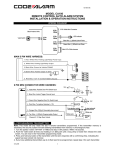
1
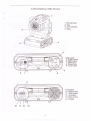
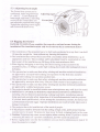
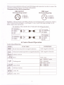
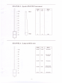
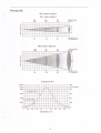
IN
MH 250W
USER MANUAL
Please read over this manualbefore
operation the light ( E
1) Open the box and checking·
2)Safety instructions·
• • • • • • • • • • • • • • • • • ••
Page 1
• • • • • • • • • • • • • • • • • • • • • ••
Page 1
3)Operating det.erminations
• • • • • • • • • • • • • • • • • •.••
Page 2
4)Description of the device·
• • • • • • • • • • • • • • • • • • ••
Page 3
5)lnstallion
• • • • • • • • • • • • • • • • • • • • • ••••
6)Control Board Operation·
7)DMX512 Channel Function·
8) Technical specifications
• • ••
Page 4
• • • • • • • • • • • • • • • • • • ••
Page 7
• • • • • • • • • • • • • • • • • ••
Page 8
• • • • • • • • • • • • • • • • • • •••
Page 14
9) Beampath •••••••••••••••••••••••••••••
Page15
10)ELECTRICALDIAGRAM·····················
Page16
11)COMMENFAULTYMAINTAIN • • • • • • • • ~ • • • • • • • ••
Page 17
12)Maintenance and cleaning • • • • • • • • • • • • • ••••
• • Page 19
1. Open the box and checking
Congratulations on choosing our products! Please carefully read this instruction manual in its
entirety and keep it weil for using reference. This manual contained about the installation and the
relative using information of this products. Please according to this manual's relative speaking when
using this equipment.
This equipment was made of new style, high intensity plastic . It fully shows the modem times
light characteristic with beauty structure. And it was made according to CE standard. Fully up the
international standard of DMX512 agreement. Master or slave in phase contro!. Can be use in large
entertainment, theater, performing and playing hall, etc.
This product uses MSR 250/2 electrical arc lamp. When receiving this product please carefully
bring and put; and check that whether this equipment has been damaged or not during transportation.
And please also check the following thing was enc1osed:
Signal line ----------------------- one piece
Safety string ----------------------- one pleces
User Manual----------------------- one set
2. Safety instructions
Every person involved with installation
- be qualilfied
- follow the instructions of this manual
and mai!1tenance
ofthis
device have to:
CAUTION:
~
~
~
~
Keep this device away from rain and moisture!
Unplug mains lead before opening the housing!
FOR YOUR OWN SAFETY, PLEASE READ THIS USER MANUAL CAREFULL Y
BEFORE YOU INITIAL START - UP!
~ Be careful with your operations.
~ With a high voltage you can suffer a dangerous
wires!
electric
shock when touching
the
~ This device has left our premises in absolutely perfect condition. In order to maintain
this condition and to ensure a safe operation, it is absolutely necessary for the user to
follow the safety instructions and warning notes writtenin this manual.
Im portan t:
~ The manufacturer will not accept liability for any resulting damages caused by the nonobservance ofthis manual or any unauthorized modification to the device.
~ Please consider that damages caused by manual modifications to the device are not
subject to warranty.
~ Never let the power-cord come into contact with other cables! Handle the power-cord
and all connections with the mains with particular caution!
~ Make sure that the available voltage is not higher than stated on the rear panel.
~ Always plug in the power plug least. Make sure that the power-switch is set to OFFposition before you connect the device to the mains. The power-plug has to be
accessable after installing the device.
~ Make sure that the power-cord is never crimped or damaged by sharp edges. Check the
device and the powercord from time to time .
. 1.
~ by the plug. Never pull out the plug by tugging the power-cord.
~ This device falls under protection class I. Therefore it is essential to connect the
yellow/green conductor to earth.
~ The electric connection, repairs and servicing must be carried out by a qualified
employee.
~ Do not connect this device to a dimmer pack.
~ Do not switch the fixture on and off in short intervals as this would reduce the lamp s
life.
~ During the initial start-up some smoke or smell may arise. This is anormal process and
does not necessarily mean that the device is defective.
~ Do not touch the device s housing bare hands during its operation (housing becomes hot)!
~ For replacement
use lamps and fuses of same type and rating only.
CAUTION :
EYE DAMAGES !
Avoid looking directly into the light source(meant
especially
for epileptics)
!
3. Operating determinations
~ This device is a moving-head spot for creating decorative effects and was designed for
indoor use only.
~ If the device has been exposed to drastic temperature fluctuation (e.g. After transportation), do not switch it on immediately. The arising condensation water might damage
your device. Leave the device switched offuntil it has reached room temperature.
~ Never run the device without lamp!
~ Do not shake the device. Avoid brute force when installing or operating the device.
~ Never lift the fixture by holding it at the projector-head,
as the mechanics
may be
damaged. Always hold thefixture at the transport handles.
~ When choosing the installation-spot,
please make sure that the device is not exposed to
extreme heat, moistureor dust. There should not be any cables lying around. You
endanger your own and the safety of others!
~ The minimum distance between light-output
than 2 meters.
~ Make sure that the area below the installation
and the illuminated
surface must be more
place is blocked when rigging,
derigging
or servicing the fixture.Always
fix the fixture with an appropriate safety-rope. Fix the
safety-rope at the correct holes only.
~ Only operate the fixture after having checked that the housing is firmly closed and all
screws are tightly fastened.
~ The lamp must never be ignited if the objective-Iens or any housing-cover is open, as
discharge lamps mayexplose and emit a high ultraviolet radiation, which may cause
bums.
~ The maximum ambient temperature ta = 45°C must never be exceeded.
lamp is switched offandthe fixture is out of operation for 5 minutes ..
Otherwise,
the
4.Description
ofthe device
1- Moving head
2- Yoke
3- Carry handles
4 - Base
3
4
Rear panel:
5 -Power switch
6 -DMX output
7- DMX input
8- Power cord
9- Fuse holder
6
7
8
14
Front panel:
10 - Mode-button
11 - Enter-button
12 - Up-button
13- Down-button
14- Display
10
11 12
13
·3·
5.Installion
5.1 Fitting thc lamp
To insert the lamp MSR 250/2
loosen the lamp cover at the rear of head (see the drawings )
by remowing the 3 fastening screws which are marked "X, Y,Z" . Carefully pull out the
cover with the lamp socketassembly.If
changing the lamp, remove the old lamp from the
socket. Insert the lamp to the socket.
00 not install a lamp with a higher wattage! A lamp like this generates temperatures the
device is not de-signed for.Oamages caused by non-observance
are not subject to warranty.
Please follow the lamp manufacturer
notes!Oo not touch the glass-bulb with bare hands
during the installation! Make sure that thelamp is installed tightly into the lampholder
system.
Reclose the lamp cover and tighten the 3 screws .
.Lamp assembly:
Lamp ~ssembly
00 not operate this fixture with opened housing-cover!
3 phillips screws "X,Y,Z"
5.2 Lamp adjust
The WASH 250 lampholder is aligned at the
factory. Oue to differences between lamps, fine
adjustment may improve light performance.Strike
the
lamp,open the shutter and the iris,set the dimmer
intensity onto 100% and focus the light on a
flatsurface (wall).Center a hot-spot(the brightest part
of the image) by using the 3 adjustment screws
"A,B,C".Turnone
screwafter anothera quarter-turn
clokwise(counter-clokwise.
Ifyou cannot detect the
hot-spot,adjust
the lamp until the light is evenly
distributed.
3 adjustment screws "A,B,C"
·4·
5.3 Adjusting
beam angle
The Fresnellens system can be
configured in the range between
80
and 220 • To set the desired
Adjusting
beam angle, and loose 2 adj \Isting
screws on the Fresnellens unit
and adjust the required beam angle.
Tighten the adjusting screws again
and fix back the front cover.
screw~/
'/
5.4 Rigging the fixture
DANG ER TO LIFE:Please consider the respective national norms during the
installation!The
installation must only be carried out by an authorized dealer!
~ The installation of the projector has to be built and constructed in a way that it can hold
10 times the weight for 1 hour without any harming deformation.
~ The installation must always be secured with a secondary safety attachment, e.g. an
appropriate catch net. This secondary safety attachment must be constructed in a way
that no part ofthe installation can fall down ifthe main attachment fails.
~ When rigging, derigging 01' servicing the fixture staying in the area below the
installation place, on bridges, under high working pI aces and other endangered areas is
forbidden.
~ The operator has to make sure that safety-relating
and machine-technical
installations
are approved by an expert before taking into operation for the first time and after
changes before taking into operation another time.
~ The operator has to make sure that safety-relating
and machine-technical
installations
are approved by an expert after every foul' year in the course of an acceptance test.
~ The operator has to make sure that safety-relating
and machine-technical
installations
are approved by a skilled person once a year.
~ The projector should be installed outside areas where persons may walk by 01' be seated.
~ IMPORTANT! OVERHEAD RIGGING REQUIRES EXTENSIVE EXPERIENCE,
including (but not limited to )calculating working load limits, installation material
being used, and periodic safety inspection of all installationmaterial
and the projector.
If you lack these qualifications,
do not attempt the installation yourself, but instead use
a professional structural rigger. Improper installation can result in bodily injury and 01'
damage to property.
~ The projector has to be installed out ofthe rea,ch of people.
~ If the projector shall be lowered from the ceiling 01' high joists, professional trussing
systems have to be used. The projector must never be fixed swinging freely in the room.
~ Caution: Projectors may cause severe injuries when crashing down! If you have doubts
concerning the safety of a possible installation, do NOT in stall the projector!
~ Before rigging make sure that the installation area can hold a minimum point load of 10
times the projector s weight.
~ The projector can be placed directly on the stage floor or rigged in any orientation on a
truss without altering its operation characteristics.
~ For overhead use, always install a safety-rope that can hold at least 10 times the weight
of the fixture. You must only use safety-ropes with screw-on carabines. Pull the safetyrope through the two apertures on the bottom of the base and over the trussing system
etc. Insert the end in the carabine and tighten the fixation screw.
Secure chain
Mounting
plate
Glamp
holde
~
Eye bolt
~
5.5 Connection
to the mains
Verify the power supply settings before applying power!
If you wish to change the power supply settings, see the chapter Appendix.
Connect the fixture to the mains with the enc10sed power cable and plug.
The earth has to be connected!
The occupation
of the connection-cables
Gable (EU)
Neutral
Earth
Live
Black
International
Pin
White
Green
Gable
L@N (US)
5.5 DMX-512 connection/connection
DMX512
is as folIows:
between fixtures
~
·6·
Only use a stereo shielded cable and 3-pin XLR-plugs and connectors
controller with the fixture or one fixture with another.
Occupation ofthe XLR-connection:
DMX-OUTPUT
XLR mounting-socket:
in order to connect the
DMX-input
XLR mounting-plug:
O.
1-Ground
2 - Signal (-)
3 - Signal (+)
.3.
1
2
2-Signal(-)
3 - Signal (+)
1 - Ground
Caution: At the last fixture, the DMX-cable has to be terminated with a terminator. Solder a
120 Q resistor between Signal (-) and Signal (+) into a 3-pin XLR-plug and plug it in the
DMX-output ofthe last fixture.
The transform of the controller line of 3 pins and 5 pins (plug and socket)
5Pins canon(socket)
Pin 1: GND(SCREEN)
Pin 2: Signal(-)
Pin 3: Signal(+)
Pin 4: N/C
Pin 5: N/C
3Pins canon(plug)
Pin I: GND(SCREEN)
Pin 2: Signal( -)
Pin 3: Signal(+)
3Pins canon(socket)
Pin I: GND(SCREEN)
Pin 2: Signal(·)
Pin 3: Signal(+)
5Pins canon(plug)
Pin I: GND(SCREEN)
Pin 2: Signal( -)
Pin 3: Signal(+)
Pin 4: N/C
Pin 5: N/C
6.Control board Operation
Control board Function
:
ON
OFF
,-
C -,
LR.E,HERI=
DMX512
CONDITION
on mode
pr1=.
Automatie direction
FUNCTION
Lamp
off
YES--reset
YES--negative
Reset
Software
Address
Lamp
hot
code
version
setpositive
MODE
error
Vertical
movement
in positive
or negative
directior
Pan
Lamp
movement
switch
in
or negative
direction
Working
mode
SLRE Slave mode
OFF
1.:
Sc
-9
;
-10
--
CHANNEL 1: PAN
\ /
-2
-4-10
-6
-7
-3
-8
-5
Value
r,
Clockwise
O· ~O·
0100
Effect
%
ratation
255
0
-6
-9
-1
~
CHANNEL2:
1\
l
-7
-4
-20-10
-3
-5
-8
~
TILT
\ /
~
Anti-clockwise
0100E
%ffect O· -
Value
ralalion
280·
255
·9·
0
CHANNEL
l
Fast
-0 1Siow
5: Speed ofPAN/TILT
rH
-4
-1 -10
-7
-6
-2
-9
-3
-5
movement
Value
100
0 Effect
Fast
Siow
%
255
8
0
CHANNEL
J
~-
.---11 -1
-7
-4
-2
-9
-6
-5
-3
-8
-10
-0
6: Lamp on/off & reset
on after
Lamp
off
after
90-93
94-100
function
0-49
No
50-54
55-89
Effect
% fllnction
Value
3 seconds
3 seconds,
Reset
240-255
140-229
0-127
230-239
128-139
. 11 .
Beampath:
Min.beam angle 8°
Min. beam angle 8°
208
2240
832
8960
92
52 Foot-ccndles
1000
560 WX
3
I
:[2
11
I
I
I T
I I
,,'
I
11
I
I I
.~ '!
I
I
00
I
1
g>
'c
~o
o
E 1
ro
~ 2
3
10
1,4
5
0,7
15
20 Distance (m)
2,8 Diameter(m )
2,1
Max. beam angle 22 °
376
4050
4
3
:[2
.~ 1
c:
~o
o
E 1
ro
~ 2
3
4
5
10
1,94
3,89
Distance=5m
10000
...•.
)
on angle
f--
/
\
(LUX)
~"-
Y
,~
/
\
V,"
.......
......
.......
"....
~
radiation angle
........
,,:/,-'B'
"
"\
8000
""
/
....
.......
1'\
""
/
"
........
-
........
929
(Foot-candles)
743
6000
557
4000
371
2000
186
o
,
1
02
0,8
0,6
0,4
0,2
0
0,2
Diameter (m)
·15·
0,4
0,6
0,8
1
0
COMMEN FAULTYMAINTAIN
5 METERS
SETS
42BYGH026-IMOTOR
18-06-0009-02
BOAR
DFOR
REAL YCABLE
OF MAIN
BOARD
FAUL TY
447HTD/GT
3MllO"C
ORRPP3
IOAl250V
2108L
WEIGHT6mm
R
16-00-0008-04
07-07-0250-02
15-00-0033-00
00-4N25-00
FBOTTOM
AN
ON
HEAD
OF
LIGHT
15-00-0076-00
MOTOR
23HSOOO
FOR
1-02MOTOR
COLOR
WHEEL
26-2A-2108Dl-00
12VDC
FAN
PART
08-05-0400-03
42BYGH004-0
1MOTOR
06-00-B002-00
42BYGH026-2MOTOR
27-04-0010-00
15-00-0073-00
16-00-0008-04
SHOW
80x80X25
BOARD
FAULTY
12VDC
FANTY
09-00-3151-00
26-2A-2107Dl-00
27-00-0010-04
06-03-Z025-00
250W
FAUL
SHOW
POWER
MAIN
TY
BALLAST
ANALYSIS
BOARD
PCB
SWITCH
11-10-00
BNo
ELECTRONIC
I 0-00
TRIGGER
26-2A-2108DI-00
00-8958252-00
11-01-0002-00
4N25
REAL
YOPTOCOUPLER
FAUL
TYFAUL
15-00-0033-00
COLOR
NOT NOT
CHANGE
WHEEL
COLOR
CAN
FAN
ON
OF
LIGHT
FAULTY
26-2A-21
07XY
-00
FAULTYPART
80x80X25
FUSE
06-00-B006-00
MOTOR
FOR
DIMMER
FAULTY
Y
FAULTY
BALLAST
FAULTY
EFFECT
WHEEL
CAN
MOTOR
FOR
STROBEFAULTY
BREAK
CAN
ADJEST
WHETHER
TITL
THE
OR
SIGNAL
NOT
STRAP
CABLE
OF
TlL
GOOD
TY BREAK 420HTD/GT
18-06-0009-01
WEIGHT6mm
MOTOR
FOR
EFFECT
WHEEL
MAIN
BOARD
OPTCOOUPLER
FAUTL
FAULTY
42BYGH026-2MOTOR
E
SWITCH
DlSPLA
Y
FAUTL
Y MSD
3M ORRPP3
250/2
08-07
-0020-00
ONTROLLED
LlGHTI
FAULTY
PHONMENON
DISPLA YCPU
WORK
BUT NOT
CAN WORK
NOT
ON
OBE
NOT RESEAT CAN
NOT CAN
DIMMER
TRANS FORMER (230V)
DlSPLA Y
LE
MER
(11 OV)
TRIGGER FAUL TY
·17·
9. Maintenance
lt is absolutely
essential
and cleaning
that the fixture is kept clean and that dust, dirt and smoke-fluid
residues must not buildup on or within the fixture. Otherwise,
::
be significantly
reduced.
light-output
will
Regular cleaning willnot only ensure the maximum light-output,
but will also allow the fixture to function reliably throughout
moistened
the fixtures
with any good glass cleaning fluid is recommended,
its life.A soft lint-free cloth
under no circumstances
should alcohol or solvents be used!
DANGER :Disconnect
from the mains before starting
The front objective
anymaintenance
lens will require weekly cleaning as smoke-fluid
up residues, reducing thelight-output
very quickly. The cooling-fans
work
tends to building
should be cleaned
monthly.
The gobos may be cleaned with a soft brush. The interior of the fixture should be
cleaned at least annually using a vacuum-cleaner
The dichroic colour-fiIters,
the gobo-wheel
or an air-jet.
and the intemallenses
should be cleaned
monthly.
To enSllre a proper fllnction ofthe gobo-wheel
intervals. The qllantity of oil must not be excessive
the gobo-wheel
, we recommend
lubrication
in six month
in order to avoid that oil runs out when
rotates.
There are no serviceable
refer to the instructions
parts inside the device except for the lamp and the fuse.Please
under "Fitting/Exchanging
operations
are only to be carried out by authorized
Rcplacing
thc fusc
I f the lamp bums out, the fine-wire
the fuse, unplug mains lead.
on the rear panel of thc base with a fitting screwdriver
2) Remove the old fuse from the fuseholder.
in the fllseholder.
4) Replace the fllseholder
dealers.
replacing
housing (anti- clockwise).
3) lnstall thc ncwfuse
and service
fuse of the device might fuse, too. Only replace the
fuse bya fuse of same type and rating.Before
Proccdure:
I) Unscrew thc fuseholder
the lamp" .Maintenance
in the housing and fix it.
·19·
from the