1
Chapter 1: Module Overview
1-3
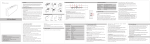
The illustration below shows the module’s hardware features.
Item
1
2a
2b
3
4
5a
5b
6
7a
7b
8a
8b
9
10
10a
10b
11
Description
Bus lever
Upper panel mounting tab
Lower panel mounting tab
Module status LED
Module door with terminal identification label
Movable bus connector (bus interface) with female pins
Stationary bus connector (bus interface) with male pins
Nameplate label
Upper tongue-and-groove slots
Lower tongue-and-groove slots
Upper DIN rail latch
Lower DIN rail latch
Write-on label for user identification tags
Removable terminal block (RTB) with finger-safe cover
RTB upper retaining screw
RTB lower retaining screw
CJC sensors
1.1.5 General Diagnostic Features
The module contains a diagnostic LED that helps you identify the source of problems that
may occur during power-up or during normal channel operation. The LED indicates both
status and power. Power-up and channel diagnostics are explained in Chapter 5,
Diagnostics and Troubleshooting.
Section 1.2
System Overview
The modules communicate to the controller through the bus interface. The modules also
receive 5 and 24V dc power through the bus interface.
User’s Manual Pub. 0300244-01 Rev. A