1
Documentation DDC4000
Documentation DDC4000
Documentation to set up and maintain the DDC4000.
Version
released
for DDC4000
Released by Comment
0.10 v. 14.10.2004 ß test
-
To use as part of the ß test.
0.11 v. 21.10.2004 -
-
Updating
0.12 v. 13.12.2004 ß
-
Manual influence in DDC, network settings for PPP,
0.13 v. 05.01.2005 ß
-
Directory structure reworked, expression corrections initiated by Wlk/FE
0.14 v. 10.03.2006 Version 1.0.xx PAW
System objects reworked (FAX, EMAIL, Config)
0.15 v. 21.3.2006
Software objects reworked (additions on the basis of the
specifications)
Version 1.0.xx PAW
0.16 v. 04.04.2006 Version 1.1.xx PAW
general revision, system objects added
1.0 v. 23.05.2006
first variant for export
Version 1.1.xx PAW
1. Introduction
2. Operation
3. Plant components and bus systems
4. Software structure
Version 05/06
Introduction
1. - 2
1. Introduction
1. Introduction .................................................................................................................................... 2
1.1. The idea behind the DDC 4000 ................................................................................................... 3
1.2. Structure of the DDC 4000 system ............................................................................................. 5
Version 05/06
Introduction
The idea behind the DDC 4000
1.1. - 3
1.1. The idea behind the DDC 4000
The DDC4000 Central Units and bus modules are extensions to the Kieback&Peter product range
providing a plant with new options.
The following objectives were aimed at and achieved with the development of the DDC4000 system:
Ethernet communication between the DDC4000 Central Units and BMS
The central station communication of the DDC4000 system is implemented over the Ethernet.
Through the use of current network technology it is possible to connect to the service laptop, BMS
or customer networks as well as to network various DDC4000 Central Units cost-effective.
If an existing JY(St)Y cabling is to be used there is still the option of communicating via this
traditional "telephone cable". But for this it is not possible to use the Ethernet's data rate.
Flexible, user-friendly user interface
The use of a touch screen TFT color display provides a flexible, future-oriented interface that is
easy and intuitive to operate and does not have restrictions for future extensions.
BACnet native
The DDC4000 communicates via the standardized protocol BACnet. BACnet operates in the DDC
Central Unit down up to the database structure. This is called a native BACnet implementation.
Each parameter is administrated as a BACnet object and for example transported to the BMS. This
means unproblematic connection to BACnet clients and therefore minimal projecting effort.
Structured parameterizing
By illustrating individual plants and their classification in groups, a clearly structured, re-usable
projecting is possible. On that ground existing plant elements can be combined with new ones with
the lowest effort.
Remote control via any Windows PC without additional software
To operate and project a DDC4000 central unit you only need a network connection and Internet
explorer. No plug-in or additional programs are required. The usual port 80 is used for
communication.
As a result of the Internet integration, access is possible from almost anywhere in the world.
checked controls for plant elements
The hardware objects, commented later, provide all the usual functions to control the common
plant parts, such as pumps, valves, burners etc. The processing of many functions such as
operating hour counting and command execution check has already been integrated and is ready
for use.
2 CAN buses for each DDC4000 central station (each can be switched as a control cabinet
or field bus)
Both CAN buses can be used as either a field bus or control cabinet bus. This permits higher
flexibility for utilizing resources. Many of the known bus devices from the DDC3000 system can still
be used; new modules will receive additional functions.
Switch modules on the touch screen
With the depiction of switches, lamps and values you can easily and effectively implement the
individually produced manual operating level.
separate customer and service interface
The service interface is separate from the intuitive operating interface. It provides a structured and
fast access to all functions. The complete plant functionality can be produced or changed from this
interface.
Integration in the planning tool
For fast and effective DDC4000 projecting the planning system PS4000 provides all kinds of
support. A flexible database structure ensures that the new DDC4000 functions can be used
immediately in the planning system.
Version 05/06
Introduction
The idea behind the DDC 4000
1.1. - 4
high computing power
Through the use of modern processors, new memory components and the use of the futureoriented and apparently virus-free Linux operating system very powerful DDC Central Units are
created.
Version 05/06
Introduction
Structure of the DDC 4000 system
1.2. - 5
1.2. Structure of the DDC 4000 system
The DDC4000 system is designed hierarchically. The DDC Central Units are as processing units
connected with each other via the central bus. The plant was designed for Ethernet operation with
10/100MBit. If existing cable has to be used it is also possible to communicate via J-Y(St)Y.
Superior, but in the same bus system (Ethernet) are the BMS and PCs with visualization via Internet
Explorer.
The bus modules and field bus controllers are located under the DDC Central Units. Modules on two
different bus systems are used to input and output information.
The control cabinet bus can accept and transfer data at very high speeds. It is used to input a lot of
information in the control cabinet and can be used for distances up to 200 meters. Typical modules in
the control cabinet bus are BMD4064 and SBM42.
The field bus can transfer data at very high speeds. It is used to collect and output distant
information. The amount of transportable information is lower than at the control cabinet bus. It can
be used for distances up to 2000 meters. The field bus modules FBM are typical for the field bus.
Version 05/06
Introduction
Structure of the DDC 4000 system
1.2. - 6
DDC400 central units model variants
DDC4200: Color 5.7" TFT touch screen
DDC4100: Black and white screen with single button operation
DDC4400: Black box: DDC4000 Central Unit without operating elements
Displaced displays
DDC4001: touch screen to operate the complete DDC network
Structure of planning and user guidance
The functions in the DDC Central Unit are strictly classified by plant. This may for example be a
heating plant with 3 heating circuits. Within one plant parts may be grouped according to logically
related functions. One such group for example is a heating circuit with the pump, valve and
temperature sensor elements. The function of a plant component within a group and group control
functions themselves are described by objects.
An object usually comprises input parameters, function and output parameters.
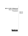
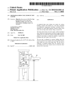
Sample plant in preparing the planning
with a number of aggregate.
Structure of information points for later
planning.
Version 05/06
Introduction
Structure of the DDC 4000 system
1.2. - 7
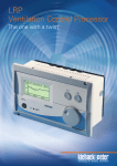
The plants are classified into groups with
logically related functions.
e.g. a heating register or a fan with
guard.
The DDC4000 objects are sub-divided for better clarity:
Software objects
The software objects have functions that control the DDC-central unit. These include for example
the basic programs heating, ventilation and separate objects such as arithmetic. The basic
programs were summarized by function. All software functions that are directly related to the basic
ventilation program are found under object number S238. This includes for example the cascade or
Y_limitation.
Hardware objects
The hardware objects describe summarized functions that are used to control plant parts. (for
example: operating pumps, fans, burners etc.)
Basic objects
Simple basic functions are implemented with basic objects as timers, markers, lamps, switches and
module clamps - the PINs.
Attached objects
Parameters may contain attached objects that change them or extend their function. For example
you can attach a "F001 scaling" function object to the "control variable sensor" parameter if this
parameter shall to be read in and scaled as a 0 ... 10V signal.
system objects
This includes functions that are processed in the DDC Central Unit. In general they are not directly
related to a plant. For example date and time settings or configuring network connections, modems
etc. are system objects.
Sub-objects
These objects are used to describe an object more precisely. A key example is a PIN. Each clamp
in the system is represented by a PIN. This PIN can be determinated by a sub-object to a digital or
analog input or output.
Therefore the parameterizing is very structured and clear.
Version 05/06
Operation
2. - 8
2. Operation
2. Operation ........................................................................................................................................ 8
2.1. Introduction to operation ............................................................................................................ 9
Version 05/06
Operation
Introduction to operation
2.1. - 9
2.1. Introduction to operation
Please refer to the DDC4000 instruction manual for detail information.
The user interface is created exclusively with the PS4000 parametering tool. Already by structuring
into plants the first operating page is determinated. Therefore there is a summary of the plants in the
DDC4000 Central Unit and a quick start bar on the first page.
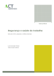
Depiction of opening page with
summary of all plants and the
quick start bar
You can obtain a quick overview of the plant's status with the aid of the quick start bar located on the
right.
Green means - plant running, white - plant is off, flashing red - plant has produced an unconfirmed
malfunction, red constant on - plant has a malfunction, hand symbol - a plant element was switched
to manual operation.
In addition it is also possible to select the desired plant very quickly with the aid of the plant indicator
shown in the middle of the screen.
Via "log in" each user can be registered on the DDC Central Unit. Depending on the code level
entered, this enables changes to the set points and times.
If one of the plant sensors located centrally on the screen is pressed the first "switch" page is
opened. This page contains the name that the group has in the DDC. All binary information that have
a tick under "visualization" in the PS4000 planning tool are found under this title, e.g. "delivery air
fan". Switch groups or LEDs are blend correspondingly. If not all switches, LEDs etc. can be depicted
on the first page it is possible to scroll forward using the "arrow keys".
Version 05/06
Operation
Introduction to operation
2.1. - 10
The formation of the "Values" page(s) is similar. All parameters that are also selected for visualization
in the PS4000 planning tool are displayed in succession (e.g. current and set points).
If times have been installed in a plant (e.g. weekly program) these are offered for selection and
editing via the "times" button.
As the depiction is set in the DDC Central Unit a change to the visualization regulations can only be
made via the PS4000 planning tool. The page settings are generated here and stored as a data
backup.
The "image" button is for version 1.0.x and 1.1.x without function. It is planned to display plant
images to make the plant easier explainable for the customer.
Status information can be
displayed in the quick start bar.
This makes it visible whether a
plant is on, off or in manual
mode. Plant malfunctions are
also visible.
Version 05/06
Plant components and bus systems
3. - 11
3. Plant components and bus systems
3. Plant components and bus systems ......................................................................................... 11
3.2. central unit bus (Ethernet) ........................................................................................................ 12
3.2.1. DDC Central Units .................................................................................................................... 12
3.2.1.1. DDC4200 ............................................................................................................................... 12
3.2.1.1.1. Connection occupancy ....................................................................................................... 12
3.2.1.1.2. Technical data .................................................................................................................... 12
3.2.1.1.3. LV help (bids) ...................................................................................................................... 14
3.2.2. Touch panel .............................................................................................................................. 16
3.2.2.1. DDC4001 ............................................................................................................................... 16
3.2.2.1.1. Connection occupancy ....................................................................................................... 16
3.2.2.1.2. Technical data .................................................................................................................... 16
3.2.3. Central communication Ethernet .............................................................................................. 16
3.2.3.1. General .................................................................................................................................. 16
3.2.3.2. Ethernet ................................................................................................................................. 17
3.2.3.2.1. Network settings Sy_Network ............................................................................................. 17
3.2.3.2.2. Other DDC Central Units in the network ............................................................................. 19
3.2.3.2.3. Ethernet tests ...................................................................................................................... 19
3.2.3.3. PC operation with a browser .................................................................................................. 20
3.2.3.5. BMS connection ..................................................................................................................... 25
3.2.3.6. BACnet ................................................................................................................................... 25
3.4. control cabinet bus .................................................................................................................... 29
3.4.1. General ..................................................................................................................................... 29
3.4.1.1. Installation .............................................................................................................................. 29
3.4.1.3. Power supply ......................................................................................................................... 29
3.4.2. BMA4024 .................................................................................................................................. 29
3.4.3. BMD4032 .................................................................................................................................. 32
3.4.4. BMD4064 .................................................................................................................................. 33
3.4.5. SBM51_04 ................................................................................................................................ 35
3.5. Field bus ..................................................................................................................................... 41
3.5.1. General ..................................................................................................................................... 41
3.5.2. Modules .................................................................................................................................... 41
Version 05/06
Plant components and bus systems central unit bus (Ethernet)
3.2. - 12
3.2. central unit bus (Ethernet)
3.2.1. DDC Central Units
3.2.1.1. DDC4200
3.2.1.1.1. Connection occupancy
Contact occupancy, device viewed from behind, to the right: D-sub plug, to the left: Ethernet socket
Please note:
Kk means a software switching option between a contact input and an output.
BY means a software switching option between an analog input and an output.
When connecting a field bus no 12 V DC voltage must be set to the DDC4200.
The SMC1 bus connection (RS232) is used for internal diagnosis purposes.
Only DDC4000 Central Units can communicated with each other via the RS485 (Z bus connection
with JY(St)Y). It is not possible to exchange data with a DDC3000 via this.
For the DDC4200 central unit a mini-UPS is available; this requires a longer starting time as the
internal energy store has to be charged. The mini-UPS can bridge power breaks of maximum 5
seconds and ensures the system software is switched off properly.
Version 05/06
Plant components and bus systems central unit bus (Ethernet)
3.2. - 13
3.2.1.1.2. Technical data
DDC control circuits
Within the DDC4200 are 12 control circuits available. This matches the range of functions in the
DDC3200.
Bus connection
Ethernet
99 DDC4000 Central Units can be administrated,
networked globally via active network components,
10/100 Mbits/s
2 CAN busses, can be switched individually as a field or control cabinet bus
– Field Bus; F Bus:
63 FieldBusModule FBM (in future there are plans for 99 FBMs);
2000m; 20kBaud, CAN, J-Y(St) Y 2x2x0,8mm²
At the point furthest from the central unit a termination resistance of 180 Ohm must be attached
between "BUS+" and "BUS-".
– Control Cabinet Bus; SBM Bus:
16 ControlCabinetBusModules SBM;
200m; 40kBaud, CAN
Interfaces
serial RS232
Modem, printer
CompactFlash
for CompactFlash card; update, data backup / file recovery (behind the front panel)
Inputs and outputs
32 binary inputs (BE), can be switched individually as binary outputs (BA) by the software
Transistor output: Contact load 24V DC; max. 50mA
Input: to be attached through potential-free contact, of which 8 BE for counting pulses to 80Hz
24 analog inputs (AE), can be switched individually as analog outputs (AA) by the software
Sensor type
Value range and unit
0..10V
0 to 100%
KP10
-50 to +150°C
Pt100
-50 to +150°C
Pt1000
-50 to +150°C
Ni100
-50 to +150°C
Version 05/06
Plant components and bus systems central unit bus (Ethernet)
Sensor type
Value range and unit
Ni1000 (DIN)
-50 to +150°C
Ni1000 (L&G)
-50 to +150°C
KP250
-50 to +150°C
ML2
-50 to +150°C
3.2. - 14
Operating voltage
for DDC Central Unit
24V AC +/-10%; 50..60Hz; 33 VA; 1,4A or
24V DC +/-10%; 14,4 VA; 0,6A or
12V DC +/-10%; 12 VA; 1,0A
For inputs and outputs
24V DC +/-10%
More data:
Fuses
Mains fuse, T 3.15A
Displays
Back-lit color TFT LCD display
Switches/ buttons
1 button to reset the device
Processor
MPC855T; 32 Bit; 80 MHz
Memory
128 MByte Flash Disc, 48MByteSDRAM;1 MByte Flash-PROM (boot)
Operating plant
Embedded Linux
Power outage data backup 10 years, clock component battery-buffered
enclosure type
IP30
Ambient temperature
0..45°C
Environmental humidity
In service: 20..80%rF, non-condensing; inoperative: 5..90%rF, non-condensing
Housing
19" short plastic cassette, 4-way cassette with a base and special connections for
Ethernet and RS232 W x H x D; 202mm x 132mm x 137mm
Front panel cutout
200.4mm x 112.0mm
Weight
2,200kg
Designation
CE
3.2.1.1.3. LV help (bids)
To complete service directories (SD)
Version 05/06
Plant components and bus systems central unit bus (Ethernet)
3.2. - 15
Automation station
Processor type: MPC 855T
Word length (bit): 32
Max. cycle time (ms): 100
AD/DA converter (bit): 16
Max buffer time, real time clock: At least 5 years
Max buffer time, data: Compact Flash unlimited
Size and type
(MB)
read-only memory: 128 MB Compact Flash
main memory: 48 MB RAM
Max. number of control circuits that can be processed: 21
Max. number of information points that can be processed
Physical: 2 x 16 x 24 binary inputs
communicative: approx. 5000
Max. number of connectable
physical input/output components: 2 x 63
Basic software functions can be extended
Type of expansion: Software objects
Local operating and display unit
Variation 1:
Does the Modular AS have
an integrated operating and display unit as standard? Yes
Variation 2:
Can the Modular AS be extended with an integratable
operating and display unit? Yes
Type: DDC4001
Variation 3:
Can an external operating and display unit
be connected? Yes
Type: PC with browser
Which services can be carried out with the operating and display unit in the variants promted above?
Variants 1, 2 and 3 can be operated, observed and parameterized.
Is bus-wide access to other Modular
automation stations possible? yes
Can an I/O component be deleted from the component bracket
without affecting other AS components
? yes (even under voltage)
Is the deletion of an I/O component from
the AS detected and is this information available
for further processing? yes
Version 05/06
Plant components and bus systems central unit bus (Ethernet)
3.2. - 16
3.2.2. Touch panel
3.2.2.1. DDC4001
3.2.2.1.1. Connection occupancy
3.2.2.1.2. Technical data
The DDC4001 includes a PC with touch screen functions. All depictions are made in full-screen mode
with Internet Explorer.
External size of DDC4001
Total dimensions W x H: (300 x 217.5) mm
Section in control cabinet W x H: (280 x 197.5) mm
Display cut-out (171 x 128) mm
Display diagonals: 213.6 mm (8.4")
3.2.3. Central communication Ethernet
3.2.3.1. General
The communication between the DDC Central Units is designed for an Ethernet connection. For this
the DDC Central Units have a socket into which the Cat cable with the RJ45 plug is inserted.
To exchange data between the DDC4000 Central Units and a BMS port #BAC0 is used (BACnet
communication).
To exchange data between the DDC4000 Central Units and a PC with Internet Explorer only port 80
is used.
To exchange data between the DDC4000 Central Units ports 19280 and 19281 are used.
Version 05/06
Plant components and bus systems central unit bus (Ethernet)
3.2. - 17
3.2.3.2. Ethernet
To use the Ethernet interface the socket on the back of the device is connected with a network cable
type Cat.5 (or Cat.6, Cat.7). A difference is made between 1:1 connection (so-called patch cables)
and cross-over cables. Cross-over cables are for directly connecting two devices, e.g. a DDC4000
and a service PC. In all other cases a patch cable should be used for example in combination with a
switch.
For communication each DDC4000 can use up to 3 IP addresses:
1. for all services when using Ethernet cabling
2. if J-Y(St)Y cabling is used and
3. for connecting via the modem (PPP)
The IP addresses and sub-network mask and any essential gateway address are provided by your
system administrator. If a closed network is to be set up, that has no connection to the outside world,
the IP addresses can be assigned freely.
The recommendation in this case is to use the addresses 192.168.1.nnn for the Ethernet connection.
This address is set by default.
3.2.3.2.1. Network settings Sy_Network
In the service interface plant "00" and group "00" must be opened. The system objects are found
there.
The Sy_Network object contains
all parameters that are important
for TCP/IP communication.
Version 05/06
Plant components and bus systems central unit bus (Ethernet)
3.2. - 18
The selection which of TCP/IP
interfaces are to be set is made
here. The following are available
for selection: Ethernet, RS485
(JY-(St)Y) and RS232 (modem).
If you type in the middle column;
the relevant parameters are
displayed.
The address is made up of 3
components.
1. The first two numbers
2. the sub-network (preset to 1
for Ethernet, 2 for RS485 and 3
for RS232)
3. central control unit address
The active IP address is made
up of this.
In the IPAdrSet you can also
state an independent number.
This is required for example if
the last number shall be > 99.
Function summary
This object contains the setting parameters for the Ethernet TCP/IP interface.
Function description
The "Ethernet IP Parameter" contains the device's TCP/IP address. If the device ID for BACnet is not
set separately in the "Sy_Module" system object ("BACnet DeviceId" parameter) the last number in
the RCP/IP address applies to the BACnetDeviceID.
Version 05/06
Plant components and bus systems central unit bus (Ethernet)
3.2. - 19
Example: 192.168.0.42 as an IP address, no separately assigned BACnetDeviceID, then "42" is
the BACnetDeviceID.
The network is switched on with the aid of the "Ethernet active" parameter. This starts the TCP/IP
and BACnet drivers.
Parameters
No.
name of parameter
parameter typ
min
max
init
unit
Gateway
Gateway
Gateway Addr.
set point
text
--
--
192.168.1.100
--
MACAdr
MACAdr
actual value
text
--
--
00:0B:64:00:00:00
--
Port
UI-Server
set point
integer
0
65535
80
--
projNo
PN
Project Number
set point
text
--
--
000-00-00000
--
projSub
PS
Project SubNetwork
set point
text
--
--
1
--
3.2.3.2.2. Other DDC Central Units in the network
TCP/IP addresses of the DDC central control units
System object Sy_Host is used to set up the network.
The TCP/IP addresses of the other DDC Central Units found in the central bus are entered in the
parameters.
The PS4000 makes the entry.
Refer to objects -> system objects -> Sy_Host
3.2.3.2.3. Ethernet tests
Communication test
In order to for example check the connection between a laptop and a DDC4000 Central Unit you
enter the following at the MS DOS entry request (Start --> Run... --> cmd.exe):
ping 172.20.11.75
Version 05/06
Plant components and bus systems central unit bus (Ethernet)
3.2. - 20
The address of the DDC4000 to be addressed has to be used. (in the above example 172.20.11.75)
A positive answer may look like this:
Ping was carried out for 172.20.11.75 with 32 Bytes data:
Response
Response
Response
Response
from
from
from
from
172.20.11.75:
172.20.11.75:
172.20.11.75:
172.20.11.75:
Bytes=32
Bytes=32
Bytes=32
Bytes=32
time<1ms
time=1ms
time=1ms
time<1ms
TTL=127
TTL=127
TTL=127
TTL=127
Ping statistics for 172.20.11.75:
Packages: Sent = 4, Received = 4, Lost = 0 (0% loss),
Approx. time in milliseconds>
Minimum = 0ms, Maximum = 1ms, Average = 0ms
Other helpful commands in the MS DOS entry request:
ipconfig
ipconfig /all
Ipconfig is a Windows program to read network data - indicates IP address, sub-network mask,
standard gateway.
Ipconfig/all displays additional information.
3.2.3.3. PC operation with a browser
The DDC Central Units can be operated remotely with the aid of a browser (e.g. Internet Explorer).
For this the Ethernet must be connected to the PC.
Only port 80 can be used for operation. As a result no extra ports need to be released.
After selecting the DDC Central Unit a java applet is loaded. This means that the J2RE (java runtime
environment) must be installed on the PC.
Is normally found on all Windows PCs but can also be loaded onto intranet.
Prerequisites
Laptop with network card, RJ45 connection
Cross-over network cable (for a 1 to 1 connection from laptop to PC) or patch network cable (when
connecting the DDC4000 e.g. via switches)
Pre-selections
The DDC4000 and laptop must be in the same network. For this it is necessary to set the IP
addresses of the DDC 4000 and the laptop to the same sub-network.
Laptop settings (using Windows XP as the example)
Version 05/06
Plant components and bus systems central unit bus (Ethernet)
3.2. - 21
In the Windows taskbar click on <Network connections> via the following path:
Start --> Settings> --> Control panel --> Network connections
Select the corresponding
connection from network
connections (e.g. LAN
connection) and right click on
<Properties>.
Version 05/06
Plant components and bus systems central unit bus (Ethernet)
3.2. - 22
In the properties window
displayed click on the <Internet
protocol (TCP/IP)> element
under <General> and click on
properties.
Version 05/06
Plant components and bus systems central unit bus (Ethernet)
3.2. - 23
A properties window for the
internet protocol (TCP/IP)
opens. Click on the "Use
following IP address" option.
Enter the relevant IP address (e.g. 192.168.0.30) and the appropriate sub-network mask (e.g.
255.255.255.0).
For the example above the DDC4000's IP address may only contain 192.168.0.xxx for
communication to be established.
After changing a firmly assigned IP address the laptop must be restarted.
DDC4000 settings
In the DDC4000 the IP address and sub-network mask must be adapted in the following parameters:
xx central unit
000 Module (Module 000)
00 plant (plant 0)
00 group (group 0)
SY_Network.01 Object.Index
EtIPAddr Parameter (IP address)
EtMask Parameter (Sub-network mask)
EtActive Parameter (switching the Ethernet to active in the DDC4000)
Version 05/06
Plant components and bus systems central unit bus (Ethernet)
3.2. - 24
The sub-network mask must be the same as in the laptop. The IP address must not be the same as
in the laptop but must match the sub-network mask. The Ethernet must still be switched on via the
<EtActive> parameter.
Now it is possible to access the DDC4000 from the laptop via Explorer. To do so enter the
DDC4000's IP address in the address field in Explorer. If it is not possible to access the DDC4000
this may be due to the "Java 2 Runtime Environment" software not being installed on the laptop. This
software must be installed and can be downloaded from the intranet from the following path:
Documents --> Technical --> DDC4000 system --> Network technology
It can also be found on the Internet by entering the search term "j2re".
The following link structure is used for opening:
1. http://
Version 05/06
Plant components and bus systems central unit bus (Ethernet)
3.2. - 25
2. DDC TCP/IP address
Sample central unit address 192.168.0.60:
In Internet Explorer window
http://192.168.0.60
3.2.3.5. BMS connection
A BMS is connected via Ethernet to the DDC4000 system. As the BACnet communication is used for
this ensure that Port #BAC0 is switched freely throughout (router...).
Caution! Version 1.0 and 1.1 do not contain BBMD (BACnet broadcast management device). This
means that communication via a router is not possible without an external BBMD.
As a result of the native abilities of the DDC4000 it is also possible to switch to third party products.
BACnet/IP is used.
Please refer to the "Ethernet" chapter for the details of the Ethernet cabling and setting up BACnet
communication.
Please refer to the BMS documentation on installing and setting up the BMS.
A modem can be connected to the serial interface. A connection to the BMS can be established via
the modem with PPP (point to point protocol).
It is not possible to directly connect the BMS via the serial interface.
3.2.3.6. BACnet
A DDC4000 system parameter becomes a transportable parameter through a BACnet attachment
function. This occurs for example by selecting the desired parameters in the BMS or the relevant
stipulations in the parameterizing tool.
What the DDC4000 can do
Medium: BACnet via Ethernet
Ethernet (ISO8802-3)
Ports: For hexadecimal range BAC0-BACF (47808 - 47823 dec.)
The DDC4000 is a B-BC. The current PICS are found on the intranet.
Initial start-up
Ensure connection:
Ethernet cable (1:1, patch cable) on the DDC to switch or router
Ethernet cable (1:1, patch cable) from laptop to switch or router
Version 05/06
Plant components and bus systems central unit bus (Ethernet)
3.2. - 26
or
Ethernet cable (cross-over) direct from DDC to laptop.
Network settings:
The customer must provide the settings even if the DDC network is not initially connected to the
customer network it is advisable to obtain the setting data from the customer so that no address
conflicts occur when connection is made later.
IP address: e.g. 192.168.8.60
Network mask: e.g. 255.255.0.0
Gateway: e.g. 172.20.11.75
Details on IP address:
Certain addresses and address ranges are assigned special functions:
127.0.0.1 - always the local computer/DDC 4000
10.x.x.x; 172.16.x.x - 172.31.x.x; 192.168.0.x - 192.168.255.x - private addresses that cannot make
direct connect with the Internet. In corporate networks addresses are normally selected from this
range. These addresses require a gateway (networked computer with Internet connection) to be able
to communicate with the Internet.
Details on network mask:
This depends on the customer's corporate network and must be provided by him.
Gateway details:
The DDC4000 contacts the Internet or other networks via this computer or if this is not required the
entry remains empty.
Use of routers
BACnet/IP works with so-called UDP telegrams. These are not fed through by routers and firewalls.
Thus no direct connection between BACnet clients in different network sections that are connected
via routers or firewalls is possible.
The use of a BBMD (BACnet Broadcast Management Device) can resolve this problem. A BBMD
packages broadcast messages in IP packages and sends these to a distance BBMD. Then a (local)
broadcast is transmitted.
The same procedure applies as appropriate for the response telegram - here the remote BBMD
sends an IP package to the local BBMD.
Only one BBMD may be used for each network section.
Caution! No BBMD is contained in version 1.0.x and 1.1.x. Access to an external device is necessary
for this.
BACnet settings
BACnet network number: e.g. 1
Device name: e.g. DDC4000 server
Device name client: e.g. DDC4000 client
Vendor name: Kieback&Peter (fixed entry)
Version 05/06
Plant components and bus systems central unit bus (Ethernet)
3.2. - 27
Vendor ID: 39 (fixed entry)
Device ID: e.g. 1
Device ID Client: e.g. 2
Model name: DDC4200
Communication: o UDP/P, o Ethernet
Operating mode: o Server, o Client, o Both
UDP port: 0xBAC 0
Details on BACnet network number:
The BACnet network number is assigned by the plant administrator and is in the range 1...65535.
The BACnet network number is used to logically differentiate between various BACnet networks.
As 6 different data link layers are supported the BACnet network number is used to differentiate for
example a BACnet/IP network from a network based on RS485. So-called routing takes place
between the various networks in order to transport information via various layers.
Device name:
Name of the BACnet server to be integrated in the DDC, must be unique.
Device ID
must be unique.
Operating mode
The DDC4000 Central Unit is currently working as a server.
Version 05/06
Plant components and bus systems central unit bus (Ethernet)
3.2. - 28
Summary
As early as the plans it should be ascertained who stipulates the required network and BACnet
settings. These should be queried and documented using the following list:
Devices
1. DDC4200
2. DDC4200
...
BMS
Version 05/06
IP address
Mask
Gateway
BACnet network number
Plant components and bus systems control cabinet bus
3.4. - 29
3.4. control cabinet bus
3.4.1. General
3.4.1.1. Installation
One peculiarity must be observed during installation:
For the BMD and BMA bus modules the electricity supply and the CAN bus can be looped through
the modules using a cascade plug.
3.4.1.3. Power supply
Performance data DDC4000
Device
AC
DC
BMD4032
90 mA
100 mA
BMD4064
90 mA
130 mA
BMA4024
280 mA
24 V DC inverse-polarity protection for all existing
3.4.2. BMA4024
Function summary
All functions of a bus module are summarized under a module of this type.
Below the module several objects and their parameters exist to handle the sub-issues in the bus
module.
The module is usually created via planning. This may also take place by logging on such a module to
the control cabinet or field bus.
After creating a BMA4024 other objects are installed automatically.
This results in the following object structure:
01 <central unit>
101 <Module> BMA4024
00 <plant> (always 00)
00 <group> (always 00)
P.01 <Object.Index> Pin object for contact 1
P.02 <Object.Index> Pin object for contact 2
...
P.24 <Object.Index> Pin object for contact 24
SY_Module.01 <Object.Index> (general information on the module)
Version 05/06
Plant components and bus systems control cabinet bus
3.4. - 30
For this a PIN object represents a container in which the contact is defined. For example this
switches a contact input to a contact output.
Function description
Module address
The bus module address corresponds to the technical address of its object. Modules on the CAN bus
1 of the central control unit occupy the technical addresses 101 to 116, according to the bus
addresses 1 to 99. The same applies to the modules on CAN bus 2 - they occupy the technical
addresses 201 to 216.
Please note: The issues of the 1st CAN bus are handled by the system object under //
000/00/00/SY_CAN.01. SY_CAN.02 is responsible for the 2nd CAN bus.
Clamp depiction
(Refer also to the description of the Pin object.)
All functions of a logical terminal are handled from the corresponding Pin object.
The logical contact connections (logical terminals 1 to 24 (b1 to b24 or Y1 to Y24) match the Pin
objects P.01 to P.24. The number of the physical contact connection (screw terminal number) does
not match a Pin object.
(e.g.: screw terminal number 55 = logical terminal 1 = P.01)
P.xx/Pin type selection determines which function objects are attached to the Pin object.
Analog input P.xx/CAI.01, Analog output P.xx/CAO.01
(Refer also to the description of the Pin object.)
Each terminal can be configured to an analog input for various sensor types or to an analog output
with acknowledgement.
The sensor type is selected from P.xx/CAI.01/SType. The selection parameter provides all the
options for the bus module. The terminal's sensor value is available via P.xx/CAI.01/b.
The unit depends on the sensor type set and the current module firmware. The value is "invalid" for a
sensor break or short circuit. Possible values for the BMA4024 (details under "sensor types"):
Sensor type
Value range and unit
0..10V, KP10, Pt100, Pt1000, Ni100, Ni1000 (DIN), Ni1000 (L&G), KP250, ML2
The output value is expected on P.xx/CAO.01/Y. Unit is "%".
The returned output value is available onP.xx/CAO.01/y, unit is %.
Version 05/06
Plant components and bus systems control cabinet bus
3.4. - 31
General parameters SY_Module.01
(Refer also to the description of the system objectSY_Module.)
In SY_Module.01 the general parameters that each module offers are stored.
Peculiarities:
899 = Version number of the firmware module
Active = The module is reachable and has full function. (If the central unit loses contact with the
bus module, SY_Module.01/Active is set to 0.)
DubAdr = The module notifies a double address.
malfunction = The module notifies a malfunction. (If the module detects a malfunction itself sets
SY_Module.01/malfunction to 1 and provides and malfunction code to SY_Module.01/Err No.)
ErrNo = malfunction code. Warnings and malfunction messages are coded here. The importance
can only be queried in the R&S.
Terminal occupancy
Version 05/06
Plant components and bus systems control cabinet bus
3.4. - 32
3.4.3. BMD4032
Function summary
All functions of a bus module are summarized under a module of this type.
Below the module several objects and their parameters exist to handle the sub-issues in the bus
module.
The module is usually created via planning. This may also take place by logging on such a module to
the control cabinet or field bus.
After creating a BMD other objects are installed automatically.
This results in the following object structure:
01 <central unit>
101 <Module> BMD
00 <plant> (always 00)
00 <group> (always 00)
P.01 <Object.Index> Pin object for contact 1
P.02 <Object.Index> Pin object for contact 2
...
P.30 <Object.Index> Pin object for contact 30
...
SY_Module.01 <Object.Index> (general information on the module)
For this a PIN object represents a container in which the contact is defined. For example this
switches a contact input to a contact output.
Function description
Module address
The bus module address corresponds to the technical address of its objects. Modules on the CAN
bus 1 of the central device occupy the technical addresses 101 to 116, as per the bus addresses 1 to
16. The same applies to the modules on CAN bus 2 - they occupy the technical addresses 201 to
216.
Note: The issues of the 1st CAN buses are handled by the system object
under//000/00/00/SY_CAN.01. SY_CAN.02 is responsible for the second CAN bus.
Clamp depiction
(Refer also to the description of the Pin object.)
All logical terminal functions are handled from the corresponding Pin object.
The logical contact connections (logical terminals) 1 to 32/64 (k1 to k32/64 or K1 to K32/64) match
the Pin objects P.01 to P.32/64. The number of the physical contact connection (screw terminal
number) does not match a Pin object.
(e.g.: screw terminal number 4 = logical terminal 1 = P.01)
Version 05/06
Plant components and bus systems control cabinet bus
3.4. - 33
P.xx/Pin type selection determines which function objects (sub-objects) are attached to the Pin
object. The module object depends on a CDI (digital input function) and a CDO (digital output
function).
Digital input P.xx/CDI.01, Digital output P.xx/CDO.01
(Refer also to the description of the Pin object.)
Each terminal is configurable to the digital input or digital output with acknowledgement.
The digital input value is available from P.xx/CDI.01/k. The output value is expected on
P.xx/CDO.01/K. The returned value from the output is available on P.xx/CDO.01/k.
General parameters SY_Module.01
(Refer also to the description of the system objectSY_Module.)
In SY_Module.01 the general parameters that each module offers are stored.
Peculiarities:
899 = Version number of the firmware module
Active = The module is reachable and has full function. (If the central unit loses contact with the
bus module SY_Module.01/Active is set to 0.)
DubAdr = The module notifies a double address.
malfunction = The module notifies a malfunction. (If the module detects a malfunction itself it sets
SY_Module.01/malfunction to 1 and provides and malfunction code to SY_Module.01/Err No.)
ErrNo = malfunction code. Warnings and malfunction messages are coded here. The importance
can only be queried in the R&S.
Terminal occupancy
3.4.4. BMD4064
Function summary
All functions of a bus module are summarized under a module of this type.
Below the module several objects and their parameters exist to handle the sub-issues in the bus
module.
The module is usually created via planning. This may also take place by logging on such a module to
Version 05/06
Plant components and bus systems control cabinet bus
3.4. - 34
the control cabinet or field bus.
After creating a BMD other objects are installed automatically.
This results in the following object structure:
01 <central unit>
101 <Module> BMD
00 <plant> (always 00)
00 <group> (always 00)
P.01 <Object.Index> Pin object for contact 1
P.02 <Object.Index> Pin object for contact 2
...
P.30 <Object.Index> Pin object for contact 30
...
SY_Module.01 <Object.Index> (general information on the module)
For this a PIN object represents a container in which the contact is defined. For example this
switches a contact input to a contact output.
Function description
Module address
The bus module address corresponds to the technical address of its objects. Modules on the CAN
bus 1 of the central device occupy the technical addresses 101 to 116, as per the bus addresses 1 to
16. The same applies to the modules on CAN bus 2 - they occupy the technical addresses 201 to
216.
Note: The issues of the 1st CAN buses are handled by the system object
under//000/00/00/SY_CAN.01. SY_CAN.02 is responsible for the second CAN bus.
Clamp depiction
(Refer also to the description of the Pin object.)
All logical terminal functions are handled from the corresponding Pin object.
The logical contact connections (logical terminals) 1 to 32/64 (k1 to k32/64 or K1 to K32/64) match
the Pin objects P.01 to P.32/64. The number of the physical contact connection (screw terminal
number) does not match a Pin object.
(e.g.: screw terminal number 4 = logical terminal 1 = P.01)
P.xx/Pin type selection determines which function objects (sub-objects) are attached to the Pin
object. The module object depends on a CDI (digital input function) and a CDO (digital output
function).
Digital input P.xx/CDI.01, Digital output P.xx/CDO.01
(Refer also to the description of the Pin object.)
Each terminal is configurable to the digital input or digital output with acknowledgement.
Version 05/06
Plant components and bus systems control cabinet bus
3.4. - 35
The digital input value is available from P.xx/CDI.01/k. The output value is expected on
P.xx/CDO.01/K. The returned value from the output is available on P.xx/CDO.01/k.
General parameters SY_Module.01
(Refer also to the description of the system objectSY_Module.)
In SY_Module.01 the general parameters that each module offers are stored.
Peculiarities:
899 = Version number of the firmware module
Active = The module is reachable and has full function. (If the central unit loses contact with the
bus module SY_Module.01/Active is set to 0.)
DubAdr = The module notifies a double address.
malfunction = The module notifies a malfunction. (If the module detects a malfunction itself it sets
SY_Module.01/malfunction to 1 and provides and malfunction code to SY_Module.01/Err No.)
ErrNo = malfunction code. Warnings and malfunction messages are coded here. The importance
can only be queried in the R&S.
Terminal occupancy
3.4.5. SBM51_04
The module object MO_SBM51_04 is a special type of object MO_SBM51. It is produced when subgroup /04 is assigned to object MO_SBM51.
Special behavior for malfunctions
If the module detects a malfunction itself sets SY_Module.01/malfunction to 1 and provides and
malfunction code "1" to SY_Module.01/Err No.
If the central unit loses contact with the bus module SY_Module.01/Active is set to 0.
Logical address structure
Technical address
Example:
Version 05/06
Plant components and bus systems control cabinet bus
3.4. - 36
103 SBM51_04
00 plant
00group
SY_SBM51.01 SY_SBM51
Parameter for bus release and cyclical reading
...
SY_Module.01 SY_Module
...
b1 plant
00group
H004.01 H004
Parameters for counting medium, device query
H004.02 H004
Para
...
H004.32 H004
Para
Dialing SBM51
Version 05/06
Plant components and bus systems control cabinet bus
3.4. - 37
Configuring the SBM51
System object SY_SBM51.01 summarizes the special requests of the SBM51 family. Bus release
and cycle time are placed here.
Each H004 is responsible for precisely one of the maximum 32 M bus counters.
The counter type can be stipulated in H004. This stipulation creates the parameters that belong to the
connected counters etc.
Third party devices on the
SBM51 are fond in Appendix
"b1". In this example H004 for
counter.
System object SY_Module.01 is responsible for a module's general issues. For details refer to the
description of the SY_Module.
Version 05/06
Plant components and bus systems control cabinet bus
3.4. - 38
technical bus address
Module bus address on the SBM bus
//xxx
The bus module address corresponds to the technical address of its objects. Modules on the CAN
bus 1 of the central device occupy the technical addresses 101 to 116, as per the bus addresses 1 to
99. The same applies to the modules on CAN bus 2 - they occupy the technical addresses 201 to
216.
Note: The issues of the 1st CAN buses are handled by the system object
under//000/00/00/SY_CAN.01. SY_CAN.02 is responsible for the second CAN bus.
Selection of specific SBM51
//xxx/00/00/SY_SBM51.01/Config
Module SBM51/04 is selected. Another device can be selected. This should be done carefully as it is
not possible to check for an appropriate SBM device! The SBM device itself only supplies the
information that it is a SBM51 but not whether it is a SBM51/04 or another device.
M bus counter bus address
//xxx/b1/00/H004.yy
32 gateway objects type H004 are created as a SBM51/04 can process up to 32 M bus counters.
Each gateway object is responsible for one M bus counter.
The bus address is expressed in the gateway object index. The SBM51/04 only supports the M bus
counters with addresses from 1 to 32 although the M bus knows addresses from 1 to 250.
Function description of object //xxx/00/00/SY_SBM51.01
Special SBM51 parameter: SY_SBM51.01
In SY_SBM51.01 all parameters are stored that are important for the SBM51 as a whole but are too
special for the SY_Module.
Config = Select the specific SBM51 for which the module object is responsible.
The selection is now on SMB51/04.
Enable = Bus release
Cycle = Bus cycle time. 0 = 24h, 1 = 2min.
(Compare description of the system objectSY_SBM51.)
Version 05/06
Plant components and bus systems control cabinet bus
3.4. - 39
Function description of the device objects //xxx/b1/00/H004.yy
M bus counter with bus address yy: //xxx/b1/00/H004.yy
Each object is responsible for exactly one M bus counter.
Config = Selection of consumption medium.
After selection a second Config parameter is visible from the following one.
Config EL = Selection of an electricity counter from a list.
Parameter becomes visible if the medium "electricity" is selected with Config.
Config WM = Selection of a heat volume counter from a list.
Parameter becomes visible if the medium "heat" is selected with Config.
Config WA = Selection of a water counter from a list.
Parameter becomes visible if the medium "water" is selected with Config.
(Compare description of gateway object H004.)
Function summary
Jedes installierte Objekt ist für genau ein Gerät am M-Bus zuständig. Der Objekt-Index der
technischen Adresse ist mit der Busadresse am M-Bus identisch. Über den Parameter Config wird
die Geräte-Klasse des konkreten M-Bus-Zählers ausgewählt, woraufhin ein zweiter Config-Parameter
"ConfigYY" installiert wird, über den der Geräte-Typ ausgewählt wird. Aufgrund beider Auswahlen
wird ein passendes Subobjekt installiert. ConfigYY steht für ConfigEL, ConfigWA oder ConfigWM.
Siehe dort. Die Subobjekte CD_WM und CD_WA stehen für die "Generischen Parameter" der
Geräte-Klasse, das sind die Parameter, die wirklich jeder Wäremzähler bzw. jeder Wasserzähler
bieten sollte. Alle anderen Subobjekte haben mehr Parameter als nur die generischen.
Parameters
No.
name of parameter
parameter typ
min
max
init
unit
Active
aktiv
Device active
actual value
boolean
--
--
0
--
Anfrage
Counter inquiry
set point
boolean
--
--
0
--
Config
Medium
Counting medium
set point
multistate
--
5
0
value,text
0,none
1,Electricity counter
2,Heat counter
3,Water counter
4,DDC3000-Menu
ConfigEL
Elt-Typ
Elt-Counter type
set point
multistate
--
2
0
value,text
0,Standard
1,Standard-Maximum
Version 05/06
Plant components and bus systems control cabinet bus
3.4. - 40
No.
name of parameter
parameter typ
min
max
init
unit
ConfigWA
H²O-Typ
Water counter type
set point
multistate
--
3
0
value,text
0,Standard
1,Standard-Maximum
2,Allmeas ISWZ
ConfigWM
WMZ-Typ
Heat counter type
set point
multistate
--
2
0
value,text
0,Standard
1,Standard-Maximum
Version 05/06
Plant components and bus systems
Field bus
3.5. - 41
3.5. Field bus
3.5.1. General
3.5.2. Modules
The field bus modules of the DDC3000 system are integrated step by step into the DDC4000 system.
They are subject to the same connection conditions and wiring guidelines. These modules only
"understand" an address assignment up to 63.
The circular or intranet state which modules have already been integrated.
Version 05/06
Software structure
4. - 42
4. Software structure
4. Software structure ....................................................................................................................... 42
4.1. General, background ................................................................................................................. 48
4.1.1. Addressing ................................................................................................................................ 48
4.1.1.1. Addressing examples ............................................................................................................ 53
4.1.2. Parameter types ....................................................................................................................... 56
4.1.3. Object principles ....................................................................................................................... 60
4.2. Basic functions .......................................................................................................................... 62
4.2.1. central unit address .................................................................................................................. 62
4.2.2. Time administration .................................................................................................................. 62
4.2.2.1. S118 Schedule ...................................................................................................................... 62
4.2.3. Behind the front cover ............................................................................................................... 64
4.2.4. Units .......................................................................................................................................... 66
4.3. Objects ........................................................................................................................................ 72
4.3.1. General ..................................................................................................................................... 72
4.3.2. Software objects ....................................................................................................................... 72
4.3.2.1. What are software objects? ................................................................................................... 72
4.3.2.2. All software objects ................................................................................................................ 74
4.3.2.3. S066 limiting value ................................................................................................................. 77
4.3.2.4. S083 Arithmetic ..................................................................................................................... 79
4.3.2.5. S126 MMM storage ................................................................................................................ 82
4.3.2.9. S238 Basic program PID (ventilation) ................................................................................... 84
4.3.2.9.1. S301 Y limitation ................................................................................................................. 90
4.3.2.9.2. S302 Y set .......................................................................................................................... 97
4.3.2.9.3. S303 Cascade .................................................................................................................. 100
4.3.2.9.4. S304 start up switching ..................................................................................................... 105
4.3.2.9.5. S305 Optimization ventilation ........................................................................................... 109
4.3.2.9.6. S306 Free night cooling .................................................................................................... 112
4.3.2.9.7. S307 Constant frost protection ......................................................................................... 117
4.3.2.9.8. S308 Minimum room temperature .................................................................................... 120
4.3.2.9.9. S309 Standstill .................................................................................................................. 122
4.3.2.9.10. S310 Energy selection .................................................................................................... 125
4.3.2.9.11. S311 Sequence change ................................................................................................. 129
4.3.2.9.12. S312 Limitation ............................................................................................................... 130
4.3.2.9.13. S313 SP switching .......................................................................................................... 136
4.3.2.9.14. S314 Set point glide ........................................................................................................ 139
Version 05/06
Software structure
4. - 43
4.3.2.9.15. S315 Set point correction ............................................................................................... 142
4.3.2.9.16. S316 Set point remote control ........................................................................................ 145
4.3.2.9.17. S317 XP switching .......................................................................................................... 148
4.3.2.10. S239 Basic program heating ............................................................................................. 150
4.3.2.10.1. Graphical summaries ...................................................................................................... 158
4.3.2.10.2. S300 Optimization .......................................................................................................... 161
4.3.2.10.3. S301 Y limitation ............................................................................................................. 168
4.3.2.10.4. S302 Y set ...................................................................................................................... 175
4.3.2.10.5. S312 Limitation ............................................................................................................... 178
4.3.2.10.6. S313 SP switching .......................................................................................................... 184
4.3.2.10.7. S315 Set point correction ............................................................................................... 187
4.3.2.10.8. S316 Set point remote control ........................................................................................ 190
4.3.2.10.9. S317 XP switching .......................................................................................................... 193
4.3.2.10.10. S318 Room correction .................................................................................................. 195
4.3.2.10.11. S319 Standby ............................................................................................................... 198
4.3.2.10.12. S348 Adaptive heating curve ........................................................................................ 201
4.3.2.11. S321 Enthalpy ................................................................................................................... 204
4.3.2.12. S322 Sequence ................................................................................................................. 205
4.3.2.13. S323 Binary valuation ........................................................................................................ 208
4.3.2.14. S324 Scaling ...................................................................................................................... 210
4.3.2.15. S325 MinMaxAverage ........................................................................................................ 213
4.3.2.16. S326 Time gliding .............................................................................................................. 215
4.3.2.17. S327 Pulse counting .......................................................................................................... 218
4.3.2.18. S328 Operation hours ........................................................................................................ 220
4.3.2.19. S329 Heat volume P .......................................................................................................... 221
4.3.2.20. S330 Heat volume DT ....................................................................................................... 223
4.3.2.21. S333 Ring counter ............................................................................................................. 226
4.3.2.22. S334 Spreadsheet function ............................................................................................... 229
4.3.2.23. S335 Sensor switching ...................................................................................................... 232
4.3.2.24. S337 Basic program fixed value ........................................................................................ 233
4.3.2.25. S338 Gliding ...................................................................................................................... 237
4.3.2.26. S342 Pulse output ............................................................................................................. 238
4.3.2.27. S343 E-Max ....................................................................................................................... 240
4.3.2.28. S344 Degree daily figure ................................................................................................... 251
4.3.2.29. S347 E-Max French ........................................................................................................... 252
4.3.2.30. S901 Signal generator ....................................................................................................... 264
4.3.3. Hardware objects .................................................................................................................... 266
4.3.3.1. What are hardware objects? ................................................................................................ 266
4.3.3.2. All hardware objects ............................................................................................................ 268
Version 05/06
Software structure
4. - 44
4.3.3.3. Priorities and signals ............................................................................................................ 270
4.3.3.4. Command execution check CEC ......................................................................................... 271
4.3.3.5. Operating hours ................................................................................................................... 272
4.3.3.6. Malfunction catch ................................................................................................................. 273
4.3.3.7. Malfunction message output ................................................................................................ 274
4.3.3.8. H301 Steam moistening unit constant ................................................................................. 275
4.3.3.10. H401 Electrical air heater single stage .............................................................................. 281
4.3.3.11. H402 Electrical air heater 2 stage ..................................................................................... 286
4.3.3.12. H403 Electrical air heater 3 stage ..................................................................................... 293
4.3.3.13. H404 Electrical air heater constant .................................................................................... 300
4.3.3.14. H501 Cover open/closed ................................................................................................... 305
4.3.3.15. H502 Fire protection cover with drive ................................................................................ 309
4.3.3.16. H503 Cover 3-point ............................................................................................................ 314
4.3.3.17. H504 Cover constant ......................................................................................................... 317
4.3.3.18. H601 Fan single stage ....................................................................................................... 320
4.3.3.19. H602 Fan 2 stage .............................................................................................................. 326
4.3.3.21. H604 fan constant FC/bypass ........................................................................................... 334
4.3.3.22. H611 Valve open/closed .................................................................................................... 341
4.3.3.23. H612 Valve bus drive ......................................................................................................... 346
4.3.3.24. H613 Valve 3-point ............................................................................................................ 349
4.3.3.25. H614 Valve constant .......................................................................................................... 353
4.3.3.26. H701 Burner single stage .................................................................................................. 356
4.3.3.27. H702 Burner 2 stage .......................................................................................................... 363
4.3.3.28. H703 Burner modulating 3 point ........................................................................................ 371
4.3.3.29. H704 Burner modulating .................................................................................................... 379
4.3.3.30. H801 Volume flow regulator constant ................................................................................ 387
4.3.3.31. H802 Volume flow regulator constant ................................................................................ 391
4.3.3.32. H901 Pump single stage ................................................................................................... 394
4.3.3.33. H903 Pump variable transformer ....................................................................................... 401
4.3.3.34. H904 Pump BUS ............................................................................................................... 409
4.3.3.35. H905 Double pump ............................................................................................................ 413
4.3.4. Basic objects (flags, timers, AE, AA, BE, BA) ........................................................................ 421
4.3.4.1. BO L - Lamp ........................................................................................................................ 421
4.3.4.2. BO M - Markers ................................................................................................................... 422
4.3.4.3. BO P - Pin ............................................................................................................................ 424
4.3.4.4. BO S - Switches ................................................................................................................... 426
4.3.4.5. BO S_11 - Switch single stage ON/OFF ............................................................................. 426
4.3.4.6. BO S_12 - Confirmation switch ........................................................................................... 427
4.3.4.7. BO S_21 - 2 push-button MANUAL/AUTO, ON/OFF .......................................................... 427
Version 05/06
Software structure
4. - 45
4.3.4.8. BO S_22 2 push-buttons AUTO, Manual On ....................................................................... 428
4.3.4.9. BO S_23 (as 22) .................................................................................................................. 428
4.3.4.10. BO S_31 - 3 push-buttons AUTO, Manual off, Manual on ................................................ 429
4.3.4.11. BO S_32 - 3 push-buttons AUTO/manual, Level1 ON/OFF, Level 2 ON/OFF ................. 429
4.3.4.12. BO S_41 - 4 Push-buttons AUTO, OFF, Manual Level 1, Level 2 .................................... 430
4.3.4.13. BO S_42 - 4 Push-buttons AUTO, DAY, NIGHT, OFF ..................................................... 431
4.3.4.14. BO S_51 - 5 Push-buttons Auto, off, Manual Level 1, 2, 3 ............................................... 431
4.3.4.15. BO T - Timer ...................................................................................................................... 432
4.3.5. System objects ....................................................................................................................... 433
4.3.5.1. System objects .................................................................................................................... 433
4.3.5.2. SY_Module Module settings general ................................................................................... 435
4.3.5.3. SY_Config plant configuration ............................................................................................. 436
4.3.5.4. SY_CAN CAN bus ............................................................................................................... 438
4.3.5.7. SY_Host ............................................................................................................................... 440
4.3.5.8. SY_FAX ............................................................................................................................... 441
4.3.5.9. SY_MsgMan ........................................................................................................................ 442
4.3.5.10. SY_EMAIL ......................................................................................................................... 442
4.3.5.11. Sy_Clock ............................................................................................................................ 443
4.3.5.12. SY_Serial ........................................................................................................................... 444
4.3.5.13. Sy_ModConf ...................................................................................................................... 445
4.3.5.14. SY_Network ....................................................................................................................... 446
4.3.6. Attachment functions .............................................................................................................. 448
4.3.6.1. F001 Scaling ........................................................................................................................ 449
4.3.6.3. F003 Limitation .................................................................................................................... 451
4.3.6.4. F004 catch ........................................................................................................................... 451
4.3.6.5. F005 Command execution check ........................................................................................ 451
4.3.6.6. F006 Damping ..................................................................................................................... 452
4.3.6.7. F007 Delay ........................................................................................................................... 453
4.3.6.9. F017 Object status .............................................................................................................. 453
4.3.6.12. FSelMO Selection message set ........................................................................................ 454
4.3.6.13. FAIMO Sensor monitoring ................................................................................................. 456
4.3.6.14. Set parameters .................................................................................................................. 457
4.3.6.14.1. FSource .......................................................................................................................... 457
4.3.6.14.3. F013 Simulation value .................................................................................................... 457
4.3.6.14.4. F014 Test value .............................................................................................................. 458
4.3.6.15. BACnet function objects .................................................................................................... 458
4.3.6.15.1. FB_AI analog input ......................................................................................................... 458
4.3.6.15.2. FB_AO analog output ..................................................................................................... 459
4.3.6.15.3. FB_AV analog parameters ............................................................................................. 459
Version 05/06
Software structure
4. - 46
4.3.6.15.4. FB_BI binary input .......................................................................................................... 460
4.3.6.15.5. FB_BO binary output ...................................................................................................... 460
4.3.6.15.6. FB_BV binary parameters .............................................................................................. 460
4.3.6.15.7. FB_MI multistate input .................................................................................................... 461
4.3.6.15.8. FB_MO multistate output ................................................................................................ 461
4.3.6.15.9. FB_MV multistate parameters ........................................................................................ 462
4.3.7. Sub-objects ............................................................................................................................. 462
4.3.7.1. Sub-objects .......................................................................................................................... 462
4.3.7.2. CAI analog input .................................................................................................................. 464
4.3.7.3. CAO analog output .............................................................................................................. 464
4.3.7.4. CDI binary input ................................................................................................................... 465
4.3.7.5. CDO binary output ............................................................................................................... 465
4.3.7.6. CModMO .............................................................................................................................. 465
4.3.8. Device objects ........................................................................................................................ 466
4.3.8.1. Gateway Objects ................................................................................................................. 466
4.3.8.2. Volume counter .................................................................................................................... 466
4.3.8.2.1. CD_WA volume counter ................................................................................................... 466
4.3.8.2.2. CD_WA Volume counter 01 ............................................................................................. 467
4.3.8.2.3. CD_WA Volume counter 02 ............................................................................................. 467
4.3.8.3. Electrical counter ................................................................................................................. 468
4.3.8.3.1. CD_WM Electrical counter ............................................................................................... 468
4.3.8.3.2. CD_WM Electrical counter 01 .......................................................................................... 468
4.3.8.4. SBMs ................................................................................................................................... 469
4.3.8.4.1. SBM51 .............................................................................................................................. 469
4.4. parameterizing ......................................................................................................................... 471
4.4.1. Plant structuring ...................................................................................................................... 471
4.4.1.1. Plants ................................................................................................................................... 471
4.4.1.2. Groups ................................................................................................................................. 471
4.4.2. Malfunction message management ........................................................................................ 471
4.4.2.1. Plant messages ................................................................................................................... 471
4.4.2.1.1. Messages ......................................................................................................................... 471
4.4.2.1.3. Message memory SY_MsgMan ........................................................................................ 474
4.4.2.1.4. Output definition SY_MsgOut ........................................................................................... 475
4.4.2.1.5. Selection message set FSelMO ....................................................................................... 476
4.4.2.1.6. Sensor failure message FAIMO ....................................................................................... 478
4.4.2.1.7. Modem configuration SY_ModConf .................................................................................. 479
4.4.2.1.10. Plant status - signalizing ................................................................................................. 481
4.4.2.1.11. SMS ................................................................................................................................ 482
4.4.2.1.12. Email ............................................................................................................................... 483
Version 05/06
Software structure
4. - 47
4.4.2.1.13. Fax recipient SY_FAX .................................................................................................... 484
4.4.2.2. Plant messages ................................................................................................................... 485
4.4.3. Creating the customer interface ............................................................................................. 486
4.4.4. Integrating touch screen switches .......................................................................................... 488
4.4.5. Manual analysis ...................................................................................................................... 490
4.4.6. Converting multistate to binary ............................................................................................... 491
4.4.7. Network return ........................................................................................................................ 493
4.5. Service level, data (restore) backup, updates ...................................................................... 495
4.5.1. Service level ............................................................................................................................ 495
4.5.1.1. Service level, access to parameterizing .............................................................................. 495
4.5.1.2. User administration .............................................................................................................. 496
4.5.2. Import data, backups, software updates ................................................................................ 497
4.5.2.1. Cold start, warm start, reset ................................................................................................ 497
4.5.2.2. Import data - PS4000 .......................................................................................................... 498
4.5.2.3. Data (restore) backup CF card ............................................................................................ 504
4.5.2.4. Data format .......................................................................................................................... 507
4.5.2.5. Plant software update .......................................................................................................... 507
4.5.2.6. Update bootloader ............................................................................................................... 508
Version 05/06
Software structure
General, background
4.1. - 48
4.1. General, background
4.1.1. Addressing
Address structure
In the DDC4000 system a technical address is used to structure and administrate data. This is based
on the structure for administrating technical plants (heating, cooling and control units) and their
individual components. It represents logical and physical units and their dependencies.
The functions in the DDC central unit are strictly classified by plants. This may for example be a
heating plant with 2 heating circuits (stat. heating circuit, WWB). Within one plant parts may be
grouped according to logically related functions. One such group for example is a heating circuit with
the pump, valve and temperature sensors. The function of such a plant element within the group is
described by objects. An object usually comprises input parameters, function and output parameters.
A technical address in the DDC4000 system usually has the following structure:
(Address components marked in blue are not available for parameters.)
The slash "/" is always used as a separator in the address.
Version 05/06
Software structure
Version 05/06
General, background
4.1. - 49
Software structure
Version 05/06
General, background
4.1. - 50
Software structure
General, background
4.1. - 51
More detailed explanation
Address element <central unit>
The central unit is the first element in the technical address. It can have a value in the range between
1 and 99. If this address element is not stated the own central unit is addressed. The "/" separator is
retained before the individual central unit and module address elements. This results in the address:
"//Module"
Value
Notes
01...99
If your own central device is to be address "//" is enough for central addressing
Address element <Module>
The second address element in the technical address is the module address. There are various value
ranges for this element and their meaning is shown in the following table. Each module has a unique
number within its central device.
Value
Notes
000
Address the central unit module DDC4000 itself (controls, regulators, plant information)
001...099 internal modules e.g. I/O card 1 = 001
101...199 Module addresses for the 1st CAN bus; 101...116 for S-Bus; 101...163 (future plans 101...199) for
F-Bus
201...299 Module addresses for the 2nd CAN bus; 201..0.216 for S-Bus; 201..0.263 (future plans 201..0.299)
for F-Bus
Address element <plant>
The plant is the third element in the technical address. It can have a value in the range between 0
and 99.
Value
Notes
00
Used to transfer to the DDC4000's plant information or to achieve lower hierarchy addresses.
01...99
Stating the plants within the module.
Address element <Group>
The group address is an organizational criterion within one module. It can be used in any way. Values
between 0 and 99 are permitted here. The number of a group is unique within a module. Each
module has as standard the group with number 00.
Values
Notes
00...99
Free order unit (containers). It contains one or more objects.
Address element <Object.Index>
The unique address of an object is combined out of the address of the object type and the object
index. The address element "object" describes the object type. The object type can be available
repeatedly in one group. The uniqueness of the object within the group is guaranteed by the object
Version 05/06
Software structure
General, background
4.1. - 52
index "Index". The object index always follows the object, separated by a point.
A difference is made between basic objects, hardware objects, software objects and system objects.
The differentiation is made by the first letter of the object type:
Value
Notes
L, M, P,S,T... Basic objects lamp, marker, pins, switches, timers. Further characters may follow after the
relevant starting letter. In any case the term ends with a period followed by a two digit index
number (01...99).
Hxxx.yy
Hardware object. "H" code followed by a three-digit number (x) and subsequent index code (y).
Sxxx.yy
Software object. "S" code followed by a three-digit number (x) and subsequent index code (y).
SY_...
system object. Other characters my follow after the "SY_" code. In any case the term ends with
a period followed by a two digit index number (01...99).
Address element <Sub-object>
This address element is only provided for certain objects. It is integrated under the object.
The sub-object is used to specify objects and is available only once in an object.
It contains no index.
An example for an object that provides a sub-object, is the basic object "PIN". This object implements
access to the parameters, e.g. a connection terminal for a BMD. In this, for example, a contact
connection can be set as an input or output.
Please note:
A "screw number" (i.e. a number of the physical contact connection), e.g. on a BMD must not be the
same as the PIN number. A PIN is not a physical but rather a logical contact connection.
Example: Screw 4 is PIN no. 1 because screws 1 to 3 are for the CAN bus.
The following table lists examples of sub-objects.
Value
Notes
CAI
Analog input
CAO
Analog output
CDI
Digital input
CDO
Digital output
Address element <Parameter>
The parameter is a property of an object or sub-object. An object or sub-object comprises one or
more parameters whose values influence the behavior of the object/sub-object. For this the
parameter must be unique in its object/sub-object. The parameter is an alphanumeric chain of
characters (e.g. "5891", "b", or "TAUdown")
Address element <Function object.Index>
Parameters may contain function objects that change them or extend their function. A function object
may occur several times under a parameter. The unique nature of the function object within the
parameter is guaranteed by an index. So for example you can attach to parameter "Source outside
Version 05/06
Software structure
General, background
4.1. - 53
temperature" (5103) in the basic heating program a "Source" (FSource) function object in order to
transfer the source value to parameter 5103.
Address element <parameter> of the function object
The parameter is a property of the function object. A function object is comprised of one or more
parameters whose value influence the behavior of the function object. For this the parameter must be
unique in its function object. The parameter is an alphanumeric chain of characters (e.g. "s")
4.1.1.1. Addressing examples
Example 1:
access to parameter "command" e.g. for backing up data
Central unit
For central unit 01:
/01
Module
Access to data backup is provided in the DDC4000 system information:
/01/000
Plant
Access to the data backup is through plant 00:
/01/000/00
Group
Access to data backup is through group 00:
/01/000/00/00
Object.Index
Access to data backup is guaranteed by object SY_Datsi:
/01/000/00/00/SY_Datsi.01
Sub-object
No sub-object is required for access to the "command" parameter. Therefore no sub-object is used.
Parameters
Access to the "command" parameter:
/01/000/00/00/SY_Datsi.01/Command
Function object.Index
A function object is not required for access to the "command" parameter
Parameter (of the function object)
A function object parameter is not required for access to the "command" parameter
Example 2:
Access to the "s" parameter as the source address for a "Q TO" parameter in basic heating program
Version 05/06
Software structure
General, background
4.1. - 54
Central unit
For central unit 02:
/02
Module
Access to the basic heating program is by regulating/controlling the DDC4000 and thus via Module
000:
/02/000
Plant
Access to the basic heating program is via the selection of for example a heating plant (01):
/02/000/01
Group
Access to the basic heating program is via the selection of for example a group control (01):
/02/000/01/01
Object.Index
Access to the basic heating program :
/02/000/01/01/S239.01
Sub-object
The source is located in the function object of the "Q TO" parameter in the basic heating program
object. Therefore no sub-object is addressed.
Parameters
Access to the "Q TO" parameter of object S239.01 (Basic heating program):
/02/000/01/01/S239.01/5103
Function object.Index
A function object that extends or changes the properties or includes additional functions is attached
to this "Q TO" parameter (e.g. stipulating a source for the value in the "Q TO" parameter):
/02/000/01/01/S239.01/5103/FSource.01
Parameter (of the function object)
You can stipulate the properties of the function object etc. with these parameters. In the example
parameter "s" is access and this contains the source address of the analog value :
/02/000/01/01/S239.01/5103/FSource.01/s
Example 3:
Access to a "b" parameter in the PIN object as analog input from the DDC4000 analog card
Central unit
For central unit 03:
/03
Module
Access to the analog card of the DDC4000 is via the module address 001:
/03/001
Version 05/06
Software structure
General, background
4.1. - 55
Plant
The analog card itself has no plants so plant 0 is selected (access to the PINs always via plant 0):
/03/001/00
Group
The analog card itself has no group so group 0 is selected (access to the PINs always via group 0):
/03/001/00/00
Object.Index
Access to the PIN object and therefore to the logical contact connection:
/03/001/00/00/P.01
Sub-object
The PIN object contains a sub-object. This PIN is therefore defines as an analog input (CAI):
/03/001/00/00/P.01/CAI
Parameters
Access to the "b" parameter where the analog value is located:
/03/001/00/00/P.01/CAI/b
Function object.Index
A function object is not required for access to the "b" parameter
Parameter (of the function object)
A function object parameter is not required for access to the "b" parameter
Example 4:
Access to the "101" parameter (message output) of the function object "message set" of a PIN on
e.g. a BMD4032
Central unit
For central unit 04:
/04
Module
Access to the BMD 4032 that is installed on the 1st CAN bus and as the first module:
/04/101
Plant
A BMD itself has no plant so plant 0 is selected (access to the PINs always via plant 0):
/04/101/00
Group
A BMD itself has no group so group 0 is selected (access to the PINs always via group 0):
/04/101/00/00
Object.Index
Access to the PIN object and therefore to the logical contact connection (e.g. pin 1):
/04/101/00/00/P.01
Version 05/06
Software structure
General, background
4.1. - 56
Sub-object
The pin object contains a sub-object. This pin is therefore defined as a digital input (CAI):
/04/101/00/00/P.01/CDI
Parameters
Access to the parameter "k" in which the digital logical contact status is displayed:
/04/101/00/00/P.01/CDI/k
Function object.Index
A function object is attached to this "k" parameter that extends or changes the properties or contains
additional function (e.g. outputs a message in the DDC4000 if the binary value changes from "0" to
"1"):
/04/101/00/00/P.01/CDI/k/FSelMO.01
Parameter (of the function object)
You can stipulate for example the properties of the function object with these parameters. In the
example parameter "101" is accessed and this contains the source address of the analog value:
/04/101/00/00/P.01/CDI/k/FSelMO.01/101
4.1.2. Parameter types
For parameterizing each object has a certain number of parameters. These parameters are shown in
tabular form. The types used are described in greater detail here.
Can the parameters be deleted?
In many cases a function is switched to inactive in this way.
Source or not?
A source can be linked to each parameter in the DDC4000. The value of the source then replaces the
parameter value.
In line with the importance some typical parameters always require source parameterizing. The
names of these are marked with the supplement "source" or "Q". This should make locating them
easier.
Summary
Integer
Floating comma digit
Binary value (Boolean)
Multistate
Selection list
String
Reference
Version 05/06
Software structure
General, background
4.1. - 57
Integer
The integer type has a maximum range of -2,147,483,648 to 2,147,483,647. As this size can not be
achieved in practice the value "infinity" is given in the table if this value range is not restricted.
A typical example of the integer type is operating hours. These are only recorded in full hours.
Example:
Par.No Parameter name Description
Parameter
type
Min Max
9
Set point
Integer
0
Bh
Operating hours
Operating hours counter level 1 and/or
level 2
Init Unit
+infinity 0
h
Explanation of statements:
Par.No
9
Parameter number: This number is used to address the parameter within the object. This number is
not unique in the whole system!
Parameter name
Bh
Bh ges.
Parameter name: A difference is made between basic text (here "Bh") and default text (here
"operating hours"). The basic text can be a maximum of 8 characters and can be used for
addressing. The default text is 15 characters long and provides a longer description. This description
can be adapted to the customer's wishes.
Description
set point/actual value for counting operating hours level 1 and/or level 2
The description gives information on the importance and use of the parameter as well as any
peculiarities to be observed.
Parameter type
Set point
Integer
Two pieces of information are included in the "parameter type". In the top line the term " set point" or
"actual value" is found. This states whether it is a stipulated (target) value or a calculated (actual)
value. As a result actual values can not be changed directly by the user.
The second line contains the parameter type, e.g. "integer" or "string".
Min
0
Min states the minimum value permitted (here 0). Sometimes this states the limitation from the DDC's
technological perspective and thus not every permitted value is always appropriate.
Max
Version 05/06
Software structure
General, background
4.1. - 58
+infinity
Max state the maximum permitted value (here +infinity = 2,147,483,647 which corresponds to
245,000 years) that is permitted for this parameter.
Init
0
The value stated under "Init" matches the default for the first installation of the relevant object. Here
the "0" means that the operating hours counter starts to count at "0" if it is not overwritten with a
different value.
Unit
h
The unit is only stated when this is appropriate. In this case "h" stands for "hours". This document
also includes a list of units.
Float
The float (or floating point) type has a maximum range of -3.402823466E38 to 3.402823466E38 (E38
stands for 10 to the power of 38 or seen in a different way the comma is shifted 38 positions to the
right). As this size can not be achieved in practice the value "infinity" is given in the table if this value
range is not restricted.
A typical example of the float type is outside temperature. This is only recorded in °C with 3
characters after the decimal point (as for all floating numbers) and is indicated with one character
after the point (varies with parameter).
Here a fictitious example:
Par.No Parameter name Description
5103
TO
TO
Parameter type
Outside temperature Actual value
Floating comma
number
Min
Max
Init
Unit
-999.000 999.000 0.000 ---
For general information on the states, refer to integer (above).
Binary value / Boolean
A binary value can only have the value 0 "false" or 1 "true". The corresponding meaning can be very
different and must be taken from the documentation.
Multistate
A multistate value can depict several statuses in a parameter. So for example a controller can have
the status ON, OFF or AUTO.
Version 05/06
Software structure
General, background
4.1. - 59
Par.No
Parameter name
Description
Parameter type
Min
Max
Init
Unit
5175
Source remote control
--
Actual value
Status value
--
4
1
BACnet,DDC_No.,Text
4, 0, OFF
2, 1, day
1, 9, Auto
3, 35, night
The information on the status value are more complex and so they are worth handling in greater
detail:
The "unit" column lists a small table that shows the potential statuses. Here the first column
("BACnet" title" states the numbering of the statuses as used in BACnet. The BACnet standard
prescribes the numbering of the available statuses from 1 consecutively to n (number of statuses).
This does not match the approach at Kieback&Peter.
The Kieback&Peter numbering is found in the second column (title "DDC no."). For Kieback&Peter
numbering the same numbers always have the same meaning, which can mean that the number 0,1
and 9 (for OFF, ON, AUTO) are used.
The importance is to be read in the third column (status text).
The table is sorted by the Kieback&Peter numbering.
The "Init" column states the preset status. This is BACnet numbering!
The "Max" column indicates the highest BACnet index.
Selection list
A selection list enables you to choose from several statuses for a parameter.
Example:
Par.No
Parameter name
Description
Parameter type
Min
Max
Init
Unit
5127
Uncontrolled condition
--
Set point
pull list
--
--
0
Selection list
BitPos,Text
0, YL1
1, YL2
2, YL3
3, YL4
For this the parameter is viewed in its binary depiction form. A bit (bit position) is used for each
status.
In this example this means when YL2 and YL are to be selected:
binary: 0110 = decimal: 6
If YL1, YL2 and YL3 are to be selected this looks as follows:
binary: 0111 = decimal: 7
Version 05/06
Software structure
General, background
4.1. - 60
If you are unfamiliar with this depiction of numbers the Windows calculator (found under accessories)
may help as long as it is switched to "scientific".
The default setting (column "Init") "0" means that no status is selected.
String
The "string" parameter type is always used when none of the other types offer adequate options. So
this is used for telephone numbers (e.g. "+49-30-60095-0") or IP addresses (e.g. 192.168.0.1).
Source/Reference
In a reference parameter type addresses that point to other parameters from where the value is to be
obtained are entered.
4.1.3. Object principles
The following image presents the key objects with a potential type of connection and use.
Version 05/06
Software structure
General, background
4.1. - 61
On all inputs analog and binary sources are parameterized. These inputs initiate a regulation in the
software objects; links are processed in the hardware objects. The output signals are then sent to the
terminals via PIN objects.
Version 05/06
Software structure
Basic functions
4.2. - 62
4.2. Basic functions
4.2.1. central unit address
4.2.2. Time administration
Please refer to the user manual for entering and operating the time control, the description is written
here from the object perspective.
4.2.2.1. S118 Schedule
Activation
Function summary
Mit Hilfe des Software-Objektes „SO_ScheduleSE“ ist es möglich, sowohl täglich wiederkehrende
Ereignisse (Wochenprogramme) als auch einmalige Zeitpunkte (Sondernutzungszeiten) zu
beschreiben.
Der Zeitplan besitzt eine Schaltzeittabelle, die die Schaltzeiten aller Ausgänge (z.B. Regler, Schalter)
verwaltet. Ein Eintrag in dieser Liste besteht aus dem Wochentag („Mo“ - „So“), der Uhrzeit im
Format hh:mm (00:00 – 23:59), einer Liste von Ausgängen die dieser Eintrag beeinflussen soll, sowie
den Wert, den jeder in der Liste befindliche Ausgang annehmen soll. Die einzelnen Schaltzeitpunkte
können jedoch nur durch eine Bedienoberfläche angezeigt, editiert oder gelöscht werden.
Version 05/06
Software structure
Version 05/06
Basic functions
4.2. - 63
Software structure
Basic functions
4.2.3. Behind the front cover
Short description of the elements behind the DDC4200 front cover
Version 05/06
4.2. - 64
Software structure
Version 05/06
Basic functions
4.2. - 65
Software structure
Basic functions
4.2.4. Units
Summary of usable units in the DDC
No.
unit
description
0
m²
Quadratmeter [m2]
1
ft²
square-feet [ft2]
2
mA
Milliampere [mA]
3
A
Ampere [A]
4
Ω
Ohm
5
V
Volt (V)
6
kV
Kilovolt (kV)
7
MV
Megavolt (MV)
8
VA
Volt Ampere (VA)
9
kVA
Kilovolt Ampere (kVA)
10
MVA
Megavolt amperes
11
VA Reac
Volt amperes reactive
12
KA Reac
Kilovolt amperes reactive
13
MVA Reac
Megavolt ampere reactive
14
cos φ
Degrees phase (Phasenverschiebung)
16
J
Joule (J)
17
kJ
Kilojoule (KJ)
18
Wh
Watt-Stunden (Wh)
19
kWh
Kilowatt-Stunden (KWh)
20
BTU
BTUs
22
ton h
Tonnen-Stunden
23
J/kg dry air
Joule pro Kg tockener Luft
24
BTU/p dry air
btu per pound dry air
25
1/h
Zyklen pro Stunde
26
1/min
Zyklen pro Minute
27
Hz
Hertz (Hz)
28
g H²O/kg
Gramm Wasser pro Kilogramm trockener Luft
29
%
Relative Feuchte (%rF)
Version 05/06
4.2. - 66
Software structure
Basic functions
4.2. - 67
No.
unit
description
30
mm
Millimeter (mm)
31
m
Meter
32
in
Inches
33
ft
Feet
34
W/ft²
Watts per square foot
35
W/m²
Watt pro Quadratmeter
36
lm
Lumen (Lichtfluss)
38
Foot Candels
Microsoft Bookshelf (American Heritage Dictionary of the English Language) defines
foot-candle as a unit of measure of the intensity of light falling on a surface, equal to one
lumen per square foot.
39
kg
Kilogramm
40
lbs
Pounds mass
41
t
Tonen
42
kg/s
Kilogramm pro Sekunde
43
kg/min
Kilogramm pro Minute
44
kg/h
Kilogramm pro Stunde
45
lbs/min
Pounds mass per minute
46
lbs/h
Pounds mass per hour
47
W
Watt (W)
48
kW
Kilowatt (KW)
49
MW
Megawatt (MW)
50
BTU/h
Btu per hour
51
HP
Pferdest
52
t
Tons refrigeration
53
Pa
Pascal (Pa)
54
kPa
Kilo-Pascal (kPa)
55
bar
Bar
56
lbs/in²
Pounds force per square inch
57
mm H²O
Zentimeter Wassers
58
in H²O
Inches of Water
59
mm Hg
Millimeter Quecksilbers
Version 05/06
en (PS) (HP)
e
e
Software structure
Basic functions
No.
unit
description
60
cm Hg
Zentimeter Quecksilbers
61
in Hg
Inches of mercury
62
°C
Grad Celsius
63
K
Grad Kelvin
64
°F
Degrees Fahrenheit
65
DDC
Gradtagzahl
66
DDF
Degree days Fahrenheit
67
Y
Jahre
68
M
Monate
69
W
Wochen
70
d
Tage
71
h
Stunden
72
min
Minuten
73
s
Sekunden
74
m/s
Meter pro Sekunde
75
km/h
Kilometer pro Stunde
76
ft/s
feet per second
77
ft/min
Feet per minute
78
mph
Miles per hour
79
ft³
Cubic feet
80
m³
Kubikmeter
81
Imp. gal
Imperial Gallons equal to 4 quarts (4.546 liters).
82
l
Liter
83
US gal
United States Gallons equal to 4 quarts (3.785 liters).
84
ft³/min
Cubic feet per minute
85
m³/s
Kubik-Meter pro Sekunde
86
Imp. gal/min
Imperial gallons per minute
87
l/s
Liter pro Sekunde
88
l/min
Liter pro Minute
89
US gal/Min
US Gallons per minute
Version 05/06
e
4.2. - 68
Software structure
Basic functions
No.
unit
description
90
°
Winkel in Grad
91
°C/h
Grad Celsius pro Stunde
92
°C/min
Grad Celsius pro Minute
93
°F/h
Degrees Fahrenheit per hour
94
°F/min
Degrees Fahrenheit per minute
96
ppm
Parts per Million
97
ppb
Parts per Billion (Milliarde)
98
%
Prozent
99
%/s
Prozent pro Sekunde
100 1/min
pro Minute
101 1/s
pro Sekunde
102 psi/°F
psi per degree Fahrenheit
103 rad
Radiant (rad)
104 1/min
115 in²
Square inches [inch2]
116 cm²
Quadratzentimeter [cm2]
117 BTU/lbs
btu per pound
118 cm
Zentimeter
119 lbs/s
Pounds mass per second
120 Δ°F
Delta degrees Fahrenheit
121 Δ°K
Temperaturdifferenz in Kelvin
122 kΩ
Kiloohm (kOhm)
123 MΩ
Mega Ohm (MOhm)
124 mV
Millivolt (mV)
125 kJ/kg
Kilojoule pro Kilogramm (KJ/Kg)
126 MJ
Mega-Joule (MJ)
127 J/K
Joule pro Grad Kelvin (J/K)
128 J/kgK
Joule pro Kilogramm Grad Fahrenheit (J/KgF)
129 kHz
Kilohertz (KHz)
130 MHz
Megaherz (MHz)
Version 05/06
4.2. - 69
Software structure
No.
unit
Basic functions
description
131 1/h
Pro Stunde
132 mW
Milliwatt (mW)
133 hPa
Hecto-Pascal (hPa)
134 mbar
Milli-Bar (mBar)
135 m³/h
Kubik-Meter pro Stunde
136 l/h
Liter pro Stunde
137 kWh/m²
Kilowattstunden pro Quadratmeter
138 kWh/ft²
Kilowatt hours per square foot
139 MJ/m²
Megajoule pro Quadratmeter
140 MJ/ft²
Megajoules per square foot
141 W/(m² °K)
Watts per square meter degree Kelvin
142 ft³/s
Cubic feet per second
143 %obs/ft
Unit percent obstruction per foot
144 %obs/m
Percent obstruction per meter
145 mΩ
Milli-Ohm
146 MWh
Megawatt-Stunden
147 kBTU
Kilo BTUs
148 MBTU
Mega BTUs
149 kJ/kg (dry air)
Kilojoule pro Kilogram trockener Luft
150 MJ/kg (dry air) Megajoule pro Kilogram trockener Luft
151 kJ/K
Kilojoule pro Kelvin
152 MJ/K
Megajoule pro Kelvin
153 N
Newton
154 g/s
Gramm pro Sekunde
155 g/min
Gram pro Minute
156 t/h
Tonnen pro Stunde
157 kBTUs/h
Kilo BTUs per hour
158 1/100s
Hundertstel einer Sekunde
159 ms
Milisekunden
160 Nm
Newton-Meter
Version 05/06
4.2. - 70
Software structure
No.
unit
Basic functions
description
161 mm/s
Milimeter pro Sekunde
162 mm/min
Milimeter pro Sekunde
163 m/min
Meter pro Minute
164 m/h
Meter pro Stunde
165 m³/min
Kubikmeter pro Minute
166 m/s²
Meter pro Sekunde zum Quadrat
167 A/m
Amperes per meter
168 A/m²
Ampere pro Quadratmeter
169 Am²
Ampere-Quadratmeter
170 F
Farad
171 H
Henry
172 Ωm
Ohm-Meter
173 S
Siemens
174 S/m
Siemens pro Meter
175 T
Tesla
176 V/K
Volt pro Kelvin
177 V/m
Volt pro Meter
178 Wb
Weber
179 Cd
Candela
180 Cd/m²
Candela pro Quadratmeter
181 K/h
Kelvin pro Stunde
182 K/min
Kelvin pro Minute
183 Js
Joule-Sekunden
256 min/K
Minutes per Kelvin
257 g/kg
Gramm per Kilogramm
Version 05/06
4.2. - 71
Software structure
Objects
4.3. - 72
4.3. Objects
4.3.1. General
Objects are consistently used in the DDC4000. This applies both for producing the firmware and for
the plant structure and projecting.
The objects visible in the service interface are classified to aid the technician with a better
clarification.
Software objects
Are functions that regulate the DDC Central Unit. These include for example the basic programs
PID and heating and separate objects such as arithmetic.
The basic programs were summarized by function. All software functions that are directly related to
the GP PID are found under object number S238. This includes for example the cascade or Y limit.
The parameters that are part of such functions are collected in folders and are therefore offered in
the service level.
Hardware objects
are summarized functions that are used to control plant parts.
Basic objects
Basic objects are for example timer, marker, switches and the terminals of modules - the PINs.
system objects
These are functions that are processed in the central unit. In general they are not directly related to
the plant. The system objects include for example setting the date and time or IP configuration.
Other objects exist within the object structure:
Attachment functions
(also called function objects). It is possible to attach functions to each parameter on the plant that
change these parameters (e.g. scaling) or expand their function (e.g. source, BACnet object).
Therefore the attachment functions are found below or on the parameters.
Sub-objects
These objects are used to more precisely describe an object. A key example a PIN. Each clamp in
the plant is represented by a PIN. This PIN can be stipulated by a sub-object on an input or output,
digital or analog.
You also find sub-objects within the SBM51.
4.3.2. Software objects
4.3.2.1. What are software objects?
Software objects are summaries of control functions in a block with input and output values. The
DDC4000 Central Units' software objects mainly match the menus of the DDC3000 system. The
functions are summarized in unchangeable and tested blocks.
Version 05/06
Software structure
Objects
4.3. - 73
The basic programs were summarized by function. All software functions that are directly related to
the GP PID are found under object number S238. This includes for example the cascade or Y limit.
The parameters that are part of such functions are collected in folders and are therefore offered in
the service level.
Parameters, names and classification
Parameters can be addressed in two different ways.
1. via the parameter number and 2. via the parameter name.
The parameter number is unique to only one object. Each object can have for example a parameter
with the number 12 and the text "Rep". For this addressing is possible in sources and links both via
language-unattached parameters and via parameter names. The use of texts instead of numbers is
advantageous for planning plant assignments and when reading sources.
However for the software objects the numbering of the DDC3000 menu was used.
A customer-specific plain text can also be set for the relevant parameter.
Version 05/06
Software structure
Objects
4.3.2.2. All software objects
List of all software objects
SWO
belongs to
S066 limiting value
S083 Arithmetic
S116 Calendar
S126 MMM storage
S238 GP_PID
GP PID
S300 Optimization
Heating
S301 Y limitation
Heating and PID
S302 Y set
Heating and PID
S303 Cascade
PID
S304 Start-up switch [draft]
PID
S305 Optimize ventilation
PID
S306 FNK
PID
S307 stet_Frost
PID
S308 min_Roomtemp
PID
S309 Standstill
PID
S310 Energy selection
PID
S311 Sequence change
PID
S312 Limitation
Heating and PID
S313 Set point switching
Heating and PID
S314 Set point glide
PID
S315 Set point correction
Heating and PID
S316 Set point remote control
Heating and PID
S317 XP switching
Heating and PID
S318 Room correction
Heating
S321 Enthalpy
S322 Sequence menu
S323 Binary valuation
S324 Scaling
Version 05/06
Heating and PID
4.3. - 74
Software structure
Objects
SWO
belongs to
S325 Min-Max-average MMM
S326 Time gliding
S327 Pulse counting
S328 Operation hours
S329 Heat volumeP
S330 Heat volumeDT
S333 Ring counter
S334 Spreadsheet function
S337 GP_Fixed value
GP Fixed value
S338 Gliding
S342 Pulse output
S343 E-Max
S344 Degree daily figure
S347 E-Max French
S348 Adaptive heating curve
Heating
S901 Signal generator (for test purposes)
object no.
name of object
release
stage: 24.07.2006
S066
Boundry value
0.1.9
S083
Arithmetic
0.2.0
S116
Calendar
unreleased
S118
Scheduler
0.3.1
S126
Store MMM
0.4.0
S193
BP FBR01/02
unreleased
S194
BP FBR03
unreleased
S195
BP FBR04
unreleased
S238
GP PID
0.1.9
S239
BP heating
0.1.9
S309
Standstill
unreleased
S321
Enthalpy
0.3.1
Version 05/06
4.3. - 75
Software structure
Objects
object no.
name of object
release
stage: 24.07.2006
S322
Sequence menu
0.1.39
S323
Binary value
0.3.1
S324
Scaling
unreleased
S325
Min/Max/Middle
0.1.47
S326
Time sliding
0.1.9
S327
Impulse count
0.4
S328
Operation hours
0.3
S329
Amt. heat calc
0.4
S330
Amt. heat DT
0.4
S333
Ring counter
0.4
S334
Table function
0.2.0
S335
Sensor switchover
0.1.47
S337
Fix value reg
0.1.9
S338
Sliding
unreleased
S342
Impuls Output
0.3
S343
E-Max
unreleased
S344
Nr. degree days
0.4
S347
E-Max france
unreleased
S901
Signal generator
unreleased
Version 05/06
4.3. - 76
Software structure
Objects
4.3. - 77
4.3.2.3. S066 limiting value
Activation
Sub-function of
all basic programs
99 times can be set
Can be switched on-off via
5748 Q EA limiting value
if not defined, ON
Function description
Analog values (measured or calculated values) can be monitored for going above or below limiting
values with the DDC software object S066 limiting value. The value to be monitored is set in the 4839
Q limiting value parameter. The stipulation of the min and max limiting value is made in the 8615
Selection (Min-Max-infringement) parameter. If the value selected in the parameter 8610 limiting
value is reached an internal contact, parameter 2 g MENU OUTPUT limiting value is set. The
switch back takes place with a switch back difference in line with parameter 8612 Xsd.
The limiting value can glide depending on any, analog command value, parameter 4832 Q
COMMAND VALUE. This guidance signal lifts or lowers the limiting value set. Any analog value in
the DDC4000 system (e.g. outside temperature) can be selected as a guidance signal.
The command value only results in a change to the set point within a glide range. The glide range is
stipulated by the parameters 8613 GLIDE START and 8614 GLIDE END.
The influence of the guidance signal on the limiting value change is determined with the parameter
8611 EF/GW. If EF is negative this can force a reduction in the set point.
The current limiting value is indicated in the parameter 3 XS akt limiting value. If no limiting value
gliding is active (COMMAND VALUE invalid or EF/GW = 0), the limiting value and XS akt limiting
value are identical. The function of the limiting value calculation can be switched ON (Status = 1) or
OFF (Status = 0) using a binary source 5748 Q EA limiting value. If no binary source is selected the
function is switched ON.
Based on the start and end of glide-ing the following calculation arises for the set point gliding:
glide start < glide end
glide end < glide start
Comvalue < glide start:
Delta_glide = 0
Comvalue < glide end
Delta_glide = EF * (glide
start - glide end)
glide start < Comvalue <
glide end
Delta_glide = EF *
(Comvalue - glide start)
glide end < Comvalue <
glide start
Delta_glide = EF * (glide
start - Comvalue)
glide end < Comvalue
Delta_glide = EF * (glide
end - glide start)
glide start < Comvalue
Delta_glide = 0
Set point = XS current (basic program) + Delta_glide
Version 05/06
Software structure
Objects
4.3. - 78
Parameters
No.
name of parameter
parameter typ
min
max
init
unit
2
g
Menu output limit
actual value
boolean
--
--
0
--
3
xsakt
Xs current Limit
actual value
float
-infinity
+infinity
0
--
4832
FG
Q GUIDE SIZE
actual value deletable
float
-infinity
+infinity
deleted
--
4839
QG
SOURCE LIMIT
actual value deletable
float
-infinity
+infinity
deleted
--
5748
EA
Q EA Limiting value
actual value deletable
boolean
--
--
deleted
--
8610
Wert
Limit
set point
float
-infinity
+infinity
95
--
8611
EF/GW
EF/GW
set point
float
-10
10
0
--
8612
xsd
Xsd
set point
float
0
999
1
--
8613
Anf
Slide begin
set point
float
-infinity
+infinity
22
--
8614
End
Slide end
set point
float
-infinity
+infinity
32
--
8615
Select
set point
multistate
--
2
1
value,text
0,Minimum
1,Maximum
Version 05/06
Software structure
Objects
4.3. - 79
4.3.2.4. S083 Arithmetic
Activation
Sub-function of
basic heating program and PID 20 times can be set
Can be switched on-off via 2153 Q EA Arithmetic
If no binary source is set the calculation is
constant.
Function summary
The DDC software object arithmetic carries out mathematic calculations.
Up to 4 analog values or also 4 digital values from the DDC4000 system and any constants can be
integrated into the calculations.
The following can be used as mathematic operators:
Basic types of calculation with sample:
+
Addition
a+b
-
subtraction
a-b
*
multiplication
a*b
/
division
a/b
^
Power
a^b
mathematical functions:
sqrt
square root
sqrt(a)
log
Logarithm on the basis of e (natural logarithm)
ln(a)
log10
Logarithm on the basis of 10 (decimal logarithm)
log(a)
exp
Exponent on the basis of e
exp(c)
sin
sine
sin(3.141)
1)
asin
arc sine
asin(1)
2)
sinh
Hyberbolic sine
sinh(a)
cos
Cosine
cos(3.141)
1)
acos
Arc cosine
acos(0)
2)
cosh
Hyberbolic cosine
cosh(b)
tan
tangent
tan(3.141/2)
1)
atan
Arc tangent
atan(1)
2)
Version 05/06
Software structure
Objects
4.3. - 80
tanh
Hyberbolic tangent
tanh(c)
abs
absolute number
abs(-3)
1) Use with radian
2) Result in radian
Logical (Boolean) expressions:
=
same
!=
not equal
&
and
|
or
<
smaller
<=
smaller than or equal
>
greater
>=
greater than or equal
Exponentials of a figure (based on 10) are implemented with the aid of "e" or "E".
e.g.: (1E2) or (1e2) provides the value 100.
The expression "exp" is used to calculate the exponents based on e.
The calculation of bracketed expressions "(..)" is possible.
The following settings must be included:
- Formula up to 50 characters in length
- Operands a, b, c and d (only small letters)
- up to 8 different, numerical constants
- Constants in decimal depiction (decimal point, leading zero for figures under zero)
- up to 7 nested brackets (incl. invisible brackets for organizing the order of calculations)
- Spaces are possible (a+b or a + b)
Parameter 2152 result depicts the result of the arithmetic calculation. This result can be set as the
analog source for other arithmetic calculations or a true value 0 or 1 (floating value).
The result is invalid:
- if a source that is not available is set as an operand
- for division by zero
- if the calculation overruns
- if the formula is entered in another wrong way
Version 05/06
Software structure
Objects
4.3. - 81
Function description
In parameter 2146 ... 2149 Arithmetic sources the maximum 4 analog sources are set. Up to 4
analog sources are set as operands a, b, c,and d in the mathematic formula.
Parameter 2151 Formula sets the mathematic formula. The mathematical formula may be up to 50
characters long. It contains operands, operators, constants and brackets.
The following settings apply:
- Formula up to 50 characters in length
- Operands a, b, c and d (only small letters)
- up to 8 different, numerical constants
- Constants in decimal depiction (decimal point, leading zero for figures under zero)
- up to 7 nested brackets (incl. invisible brackets for organizing the order of calculations )
- Spaces are possible
Parameter 2152 result depicts the result of the arithmetic calculation. This result can be set as the
analog source for other arithmetic calculations or a true value 0 or 1.
The result is invalid:
- if a source that is not available is set as an operand
- for division by zero
- if the calculation overruns
With the parameter a binary source is used to switch the execution of the arithmetic calculation. If no
binary source is set the calculation is constant. If this parameter is written with a valid zero the result
is set to zero.
Parameters
No.
name of parameter
parameter typ
min
max
init
unit
2146
Q_a
Arithmetic 1. Source
actual value deletable
float
-infinity
+infinity
deleted
--
2147
Q_b
Arithmetic 2. Source
actual value deletable
float
-infinity
+infinity
deleted
--
2148
Q_c
Arithmetic 3. Source
actual value deletable
float
-infinity
+infinity
deleted
--
2149
Q_d
Arithmetic 4. Source
actual value deletable
float
-infinity
+infinity
deleted
--
2151
Formel
Formula
set point deletable
text
--
--
2152
erg
RESULT
actual value
float
-infinity
+infinity
0
--
2153
Q_EA
Q EA Arithmatic
actual value deletable
boolean
--
--
deleted
--
Version 05/06
--
Software structure
Objects
4.3. - 82
4.3.2.5. S126 MMM storage
Activation
Sub-function of
-
20 times can be set
Function summary
The DDC software object S126 MMM storage supplies the maximum value, minimum value and
average of an analogue source. In addition the values determined by the analogue source can be
saved for a particular point of time.
2165 source MMM
plannable source on any analogue value of the DDC4000 system.
If the source is invalid or deleted the current min, max and average values are frozen. When the
source is valid again the current min, max and average values are reset to the current source value.
The saved values are not affected by this.
2166 Max act.
Maximum value determined since the time of the last reset.
2167 Min act.
Minimum value determined since the time of the last reset.
2168 Average act.
Average value calculated since the time of the last reset.
2195 Q storage
plannable source on any binary value of the DDC4000 system. With the change from "0" to "1" the
min, max and average values are reset and saved.
For example the values can be saved for a defined period of time through the use of a time program
output. Through the use of a timer the saving can be released at regular intervals.
2196 Max stor.
Maximum value at the reset time.
2197 Min stor.
Minimum value at the reset time.
2198 Average stor.
Average value at the reset time.
2199 Input stor.
Current value of the 2165 source MMM at the reset time.
Version 05/06
Software structure
Objects
4.3. - 83
Parameters
No.
name of parameter
parameter typ
min
max
init
unit
2165
Q_Input
Store Source MMM
actual value deletable
float
-infinity
+infinity
deleted
--
2166
Max
Max Value / t
actual value
float
-infinity
+infinity
0
--
2167
Min
Min Value / t
actual value
float
-infinity
+infinity
0
--
2168
Mittel
Average Value / t
actual value
float
-infinity
+infinity
0
--
2169
DATE
actual value
integer
0
0
0
--
2195
Q_Sp
Store Q
actual value deletable
boolean
--
--
deleted
--
2196
Max_s
Stored Max Value
actual value
float
-infinity
+infinity
0
--
2197
Min_s
Stored Min Value
actual value
float
-infinity
+infinity
0
--
2198
Mittel_s
Stored Average Value
actual value
float
-infinity
+infinity
0
--
2199
Input_s
Stored Input
actual value
float
-infinity
+infinity
0
--
2200
TIME
actual value
integer
0
24
0
h
Version 05/06
Software structure
Objects
4.3. - 84
4.3.2.9. S238 Basic program PID (ventilation)
Activation
Basic program
PID (ventilation)
can be set 12 x
Function summary
This basic program is a PID control with 4 sequences. Using binary source parameters integration
into the ventilation controls and regulations is possible without any problems.
Function extensions are made via DDC soft- and hardware objects.
Function description
The control variable sensor must be defined in parameter 5102 source control variable. Any
DDC4000 system analog value can be set.
As an outside sensor, any analog value in the DDC system can also be set in parameter 5103
source TO. This parameter is used in combination with other DDC sub-software objects , e.g.S307
constant frost protection. If not required, no setting is required.
In parameter 5100 XS the desired set point for the fixed value regulation is set. On the basis of this
set point and the function of other DDC sub-software objects (e.g. S314 set point gliding, S313 set
point switching) a new set point is calculated that is depicted as the current value on parameter
5101 XS current.
In the basic PID program up to 4 constant Y outputs are available. The calculation of the Y outputs is
made if the control circuit is in "Control ON" operation mode. Otherwise the Y outputs are in the
status assigned to them for the uncontrolled status by parameter 5127 uncontrolled condition. (0 =
0 %, 1 = 100 %)
The values of the Y outputs calculated by the basic program can be overwritten by manual
intervention (7801 manual intervention .. 7804 manual intervention Y04), BMS intervention (h01 ..
h04) or by DDC sub-software objects (e.g. S302 Y set).
The current values of the Y outputs are displayed in the parameters 5110 YL1... 5113 YL4.
For each Y output a max and min limit parameter 5141 .. 5148 can be set (e. g. for stipulating a
minimum outside air rate MAR).
In parameter 5126 Sequence various sequences can be set for the individual Y outputs.
The output of the Y output values occurs via source parameterizing in the basic programs of the DDC
Central Units (DDC4000) and the DDC modules (DDC bus module BMA, field bus module FBM,
control cabinet bus module SBM).
The parameters 5130 .. 5132 Xdz.. can stipulate idle zones between the individual Y output
sequences. The situation of the relevant set point can be seen from the figure.
Version 05/06
Software structure
Objects
4.3. - 85
These idle zones also work when the control circuit has an integral share, parameter 5106 tN, i. e.
the I-share is switched off on the edge of XpY. If the actual value in the Xp range of the next
sequence occurs the I-share is stocked up again. This results in the idle zone range not being run
through as a result of the effect of the I-share and a real energy saving effect is achieved.
In parameter 5128 xwh an insensitivity zone is set, i. e. within xw +/- xwh the Y outputs are not
changed. If xw exceeds this range the control is normal.
Example:
Set point point for 4 or 3 sequences
Using the central influence, remote control and usage time program the internal contact I011 plant
on is controlled in the basic ventilation program. If the fan is to be started as a result of the conditions
stated above first the internal contact I011 plant on is switched to "1".
When the subsequent control is started and there is a return message via 5140 Q Release control
the control is quitted with the internal contact I012 control on set to "1".
These and other internal contacts switch as per the status of the control circuit and can be used for
other PLC links.
Priorities
Switch basic ventilation program to normal operation
1. Highest priority:
For releasing the control a binary source is entered in parameter 5140 Q Release control e. g.
the return message from the ventilation protection. If parameter 5140 Q release control is not
set the basic program is constantly in normal operation (I012 Control ON = 1).
2. The multistate input 5138 Source remote ON with its potential modesAutomatic / source
remote on / source remote off is used to switch the plant on and off. This means remote
control and / or operating the plant independently on the usage time program set is possible.
If the source remote ON is not set or set to automatic mode, the PID basic program depends on
any remote control by a BMS or the assigned usage time program.
Version 05/06
Software structure
Objects
4.3. - 86
3. A Z contact in the PID basic program enables the central building control plant to influence the
status of ventilation control. The multistate parameter Z Z contacts can take on the Automatic /
Z1-day / Z4-off modes.
If the Z contact is not influenced or the Automatic state set the PID basic program depends on
the assigned usage time program.
4. Lowest priority:
Parameter Q_N assigns the weekly usage time and/or special holiday, bank holiday or special
usage times to a schedule object S118. If no time program is assigned to the PID basic program
the plant is always ON (I011 plant ON = 1).
Parameters
No.
name of parameter
parameter typ
min
5100 XS
XS
set point
float
5101 Xs akt
XS current
actual value
float
max
init
unit
-9999,9 9999,9
20
C
-9999,9 9999,9
0
C
5102 Qreg
actual value deletable -infinity
Source controlled variable float
+infinity deleted C
5103 TA
Source TA
actual value deletable -999
float
999
5105 xw
XW
actual value
float
-9999,9 9999,9
0
K
5106 tN
tN
set point deletable
integer
1
99
3
min
5110 Y1
YL1
actual value
float
0
100
0
%
5111 Y2
YL2
actual value
float
0
100
0
%
5112 Y3
YL3
actual value
float
0
100
0
%
5113 Y4
YL4
actual value
float
0
100
0
%
5115 Q_N
State N
actual value deletable -text
--
deleted --
5120 XPY1
XPY1
set point
float
0,5
9999,9
10
K
5121 XPY2
XPY2
set point
float
0,5
9999,9
10
K
5122 XPY3
XPY3
set point
float
0,5
9999,9
10
K
Version 05/06
deleted C
Software structure
No.
name of parameter
Objects
4.3. - 87
parameter typ
min
max
init
unit
5123 XPY4
XPY4
set point
float
0,5
9999,9
10
K
5125 D
Vorhalt
set point deletable
integer
1
299
deleted s
5126 \\//
Sequence
set point
integer
0
255
48
--
5127 NRegZust
Not controlled condition
set point
selection list
--
--
0
selection list
No.,text
0,for Y1
1,for Y2
2,for Y3
3,for Y4
5128 xwh
xwh
set point
float
0
9999,9
0
K
5130 xdz12
Xdz 12
set point
float
-9999,9 9999,9
0
K
5131 xdz23
Xdz 23
set point
float
-9999,9 9999,9
0
K
5132 xdz34
Xdz 34
set point
float
-9999,9 9999
0
K
5138 QFern
Q Remote control
actual value
multistate
--
3
2
value,text
1,Source remote ON
0,Source remote OFF
9,Automatic
5140 Q RELEASE Regelung
actual value deletable -boolean
--
deleted --
5141 Y1min
Y1 min
set point
float
0
100
0
%
5142 Y2min
Y2 min
set point
float
0
100
0
%
5143 Y3min
Y3 min
set point
float
0
100
0
%
5144 Y4min
Y4 min
set point
float
0
100
0
%
5145 Y1max
Y1 max
set point
float
0
100
100
%
5146 Y2max
Y2 max
set point
float
0
100
100
%
Version 05/06
Software structure
No.
4.3. - 88
parameter typ
min
max
init
unit
5147 Y3max
Y3 max
set point
float
0
100
100
%
5148 Y4max
Y4 max
set point
float
0
100
100
%
5169 TAm
TA middle
actual value
float
-50
150
0
C
7801 hY1
Manual influence Y1
set point deletable
float
0
100
deleted %
7802 hY2
Manual influence Y2
set point deletable
float
0
100
deleted %
7803 hY3
Manual influence Y3
set point deletable
float
0
100
deleted %
7804 hY4
Manual influence Y4
set point deletable
float
0
100
deleted %
h01
Analoge GLT influence 1
actual value deletable 0
float
100
deleted %
h02
Analoge GLT influence 2
actual value deletable 0
float
100
deleted %
h03
Analoge GLT influence 3
actual value deletable 0
float
100
deleted %
h04
Analoge GLT influence 4
actual value deletable 0
float
100
deleted %
i011
System ON
actual value
boolean
--
--
0
--
i012
Control ON
actual value
boolean
--
--
0
--
Z
Z
Z-contacts
set point
multistate
--
3
2
value,text
1,Z1 Day
0,Z4 Off
9,Automatic
*
name of parameter
Objects
Nr.
Beschreibung
1) 5115 Hier wird die Zuweisung zum Scheduler (Wochenprogramm) durchgeführt.
Dieser Parameter beschreibt den Zustand des Zeitprogramms für die Regler im folgenden Format:
aktuellerModus, nächsterModus, Zeit bis Modus Wechsel in Minuten.
Ungültige Werte ergeben sich durch weglassen.
Folgende Zustandswerte für den Modus werden unterstützt:
1=Tag, 2=Nacht, 4=Aus (Aus wird demnächst auf 0 geändert)
Version 05/06
Software structure
DDC sub-software objects
Version 05/06
Objects
4.3. - 89
Software structure
Objects
4.3. - 90
4.3.2.9.1. S301 Y limitation
Activation
Sub-function of
each heating and ventilation basic program
0 ... can be set 4 x
Can be switched on-off via
5319 Q EA Y limitation
if not linked, ON
Function summary
The DDC software object S301 Y limitation influences the min or max limits of the Y outputs for the
DDC control circuits (basic program).
A difference is to be made between two influence options that can jointly affect the basic function of
the DDC control circuits:
1. Depending on a limitation factor the Y outputs Y-min or Y-max set in the basic program for the
DDC control circuits are altered. The influence on the Y-min or Y-max occurs after the limitation
factor reaches a particular limiting value.
- For the MAX limit the limiting value must have exceeded the limiting value.
- for the MIN limit the limitation factor must be below the limiting value so as to influence the
setting range of the Y-outputs.
- By inverting the Y-limit YES / NO the direction of influencing the Y-setting range is stipulated.
2. In addition to the functions stated in 1 the limiting value of the limitation factor can itself glide in a
particular range. I.e. depending on the outside temperature (basic program) the limiting value of
the limitation factor is also changed.
Function description
Re 1:
The limitation factor is set in parameter 5311 source Y-limitation. Any DDC4000 system analog
value can be set.
The Y-limitation influences the Y-output parameterized on parameter 5310 Y-limit. on.
The DDC sub.menu Y-limit can be installed and set repeatedly for a DDC control circuit. If several Ylimitation DDC sub-menus work on the same Y output, the min and max limits calculated for each
DDC software object are added.
For the basic PID program you have to choose between the 4 potential Y outputs.
For the basic heating program the Y limit always works on the heating control for a Y output.
Parameter 5312 YB-limiting value sets the value from which the Y limit should act on the Y output
setting range.
Parameter 5313 YB limitation stipulates
whether a MAX limitation, i.e. exceeding the limiting value (image 3, image 4)
or
a MIN limitation, i.e. going below the limiting value (image 1, image 2)
should affect the setting range of the Y output.
Version 05/06
Software structure
Objects
4.3. - 91
Parameter 5314 YB Inverting stipulates the direction of the influence. (direction of curve)
5314 YB Inverting = NO -> ( image 1, image 3 ),
5314 YB Inverting = YES -> ( image 2, image 4 ),
Parameter 5315 XP Y-limitation is the proportional range within which the Y-min or Y-max for the Youtputs can be moved depending on the limitation factor.
5315 XP Y-limitation = 10 means: for 10 units change in the limitation factor Y-min or Y-max on the
Y-output is moved by 100%.
5315 XP Y-limitation = 100 means: only for 100 units change in the limitation factor is Y-min or Ymax on the Y-output moved by 100%.
Re 2:
Depending on a command value (outside temperature, source parameter 5103 source TO in the
basic program of the DDC control circuit) the limitation value stipulated in parameter 5312 YBlimitation value can glide.
The glide range is set in parameters 5317 glide start YLim and 5318 glide end YLim.
The influence of limiting value glide is set in parameter 5316 EF Ylimitation.
5316 EF Ylimitation = 1 means: When changing the command value (outside temperature) by 1 K
the limiting value stipulated in the 5312 YB-limiting value parameter is moved by 1 unit.
5316 EF Ylimitation = 10 means: When changing the command value (outside temperature) by 1 K
the limiting value stipulated in the 5312 YB-limiting value parameter is moved by 10 units.
Priorities
The y-limitations 1-4 also work on the basic program's Ymin/Ymax.
Priority
Function
Highest
Y limitations of the basic program
5141 Y1min, 5145 Y1max
Version 05/06
Software structure
Priority
Function
...
5144 Y4min, 5148 Y4max
lowest
DDC software sub-objects Y-limitation
Figure 1
Y limitation as
5313 YB-limitation = MIN
5314 YB Inverting = NO
Figure 2
Y limitation as
5313 YB-limitation = MIN
5314 YB Inverting = YES
Figure 3
Y limitation as
5313 YB-limitation = MAX
5314 YB Inverting = NO
Version 05/06
Objects
4.3. - 92
Software structure
Objects
4.3. - 93
Figure 4
Y limitation as
5313 YB-limitation = MAX
5314 YB Inverting = YES
Parameters
Parameter 5313 Min/Max selection : "yes" = "1" means Max
No.
name of parameter
parameter typ
min
max
init
unit
5310.1
Y limit. affects
set point
multistate
--
4
0
value,text
1,Y1
2,Y2
4,Y3
8,Y4
5311.1
Q1
Source Y-limitation
actual value deletable
float
-infinity
+infinity
deleted
--
5312.1
G1
YB-Limiting value
set point
float
-infinity
+infinity
150
--
5312.2
G2
YB-Limiting value
set point
float
-infinity
+infinity
150
--
5313.1
MMBegr1
YB-limitation
set point
boolean
--
--
1
--
5314.1
Inv1
YB Inversion
set point
boolean
--
--
0
--
5315.1
XP1
XP Y limitation
set point
float
1
200
10
--
5316.1
EF1
EF Y limitation
set point
float
0
10
0
--
5317.1
Anf1
Slide begin YBegr
set point
float
-infinity
+infinity
22
C
5318.1
End1
Slide end Y limit
set point
float
-infinity
+infinity
32
C
Version 05/06
Software structure
Objects
4.3. - 94
No.
name of parameter
parameter typ
min
max
init
unit
5319.1
EA1
Q EA Y-limitation
actual value deletable
boolean
--
--
deleted
--
5320.1
YBegr
Y-Limiting 1 active
actual value
boolean
--
--
0
--
No.
name of parameter
parameter typ
min
max
init
unit
5310.2
Y limit. affects
set point
multistate
--
4
0
value,text
1,Y1
2,Y2
4,Y3
8,Y4
5311.2
Q2
Source Y-limitation
actual value deletable
float
-infinity
+infinity
deleted
--
5312.2
G2
YB-Limiting value
set point
float
-infinity
+infinity
150
--
5313.2
MMBegr2
YB-limitation
set point
boolean
--
--
1
--
5314.2
Inv2
YB Inversion
set point
boolean
--
--
0
--
5315.2
XP2
XP Y limitation
set point
float
1
200
10
--
5316.2
EF2
EF Y limitation
set point
float
0
10
0
--
5317.2
Anf2
Slide begin YBegr
set point
float
-infinity
+infinity
22
C
5318.2
End2
Slide end Y limit
set point
float
-infinity
+infinity
32
C
5319.2
EA2
Q EA Y-limitation
actual value deletable
boolean
--
--
deleted
--
5320.2
YBegr
Y-Limiting 2 active
actual value
boolean
--
--
0
--
No.
name of parameter
parameter typ
min
max
init
unit
5310.3
Y limit. affects
set point
multistate
--
4
0
value,text
1,Y1
2,Y2
4,Y3
8,Y4
Version 05/06
Software structure
Objects
4.3. - 95
No.
name of parameter
parameter typ
min
max
init
unit
5311.3
Q3
Source Y-limitation
actual value deletable
float
-infinity
+infinity
deleted
--
5312.3
G3
YB-Limiting value
set point
float
-infinity
+infinity
150
--
5313.3
MMBegr3
YB-limitation
set point
boolean
--
--
1
--
5314.3
Inv3
YB Inversion
set point
boolean
--
--
0
--
5315.3
XP3
XP Y limitation
set point
float
1
200
10
--
5316.3
EF3
EF Y limitation
set point
float
0
10
0
--
5317.3
Anf3
Slide begin YBegr
set point
float
-infinity
+infinity
22
C
5318.3
End3
Slide end Y limit
set point
float
-infinity
+infinity
32
C
5319.3
EA3
Q EA Y-limitation
actual value deletable
boolean
--
--
deleted
--
5320.3
YBegr
Y-Limiting 3 active
actual value
boolean
--
--
0
--
No.
name of parameter
parameter typ
min
max
init
unit
5310.4
Y limit. affects
set point
multistate
--
4
0
value,text
1,Y1
2,Y2
4,Y3
8,Y4
5311.4
Q4
Source Y-limitation
actual value deletable
float
-infinity
+infinity
deleted
--
5312.4
G4
YB-Limiting value
set point
float
-infinity
+infinity
150
--
5313.4
MMBegr4
YB-limitation
set point
boolean
--
--
1
--
5314.4
Inv4
YB Inversion
set point
boolean
--
--
0
--
5315.4
XP4
XP Y limitation
set point
float
1
200
10
--
5316.4
EF4
EF Y limitation
set point
float
0
10
0
--
Version 05/06
Software structure
Objects
4.3. - 96
No.
name of parameter
parameter typ
min
max
init
unit
5317.4
Anf4
Slide begin YBegr
set point
float
-infinity
+infinity
22
C
5318.4
End4
Slide end Y limit
set point
float
-infinity
+infinity
32
C
5319.4
EA4
Q EA Y-limitation
actual value deletable
boolean
--
--
deleted
--
5320.4
YBegr
Y-Limiting 4 active
actual value
boolean
--
--
0
--
Version 05/06
Software structure
Objects
4.3. - 97
4.3.2.9.2. S302 Y set
Activation
Sub-function of
basic heating and ventilation program
0 ... can be set 4 x
Can be switched on-off via
5327 Q Y-SET
if not defined, ON
Function summary
With the Y-set DDC submenu the Y outputs of the DDC control circuits are stipulated by binary
signals on certain (parameterizable) Y-values. If the binary signal = 1 the stipulated Y value works on
the Y output.
Function description
The Y-set DDC software object can be installed and set up to four times for one DDC control circuit.
For this Y-set can work repeatedly on the same Y-output.
The address of the binary source is entered in parameter 5327 Q Y-SET. If the binary source ="1",
the analog value set in parameter 5326 Y-SET value (0 ..100 %) is transferred to the Y-output.
Parameter 5325 destination Y-SET sets the Y output that is to be influenced.
For the basic PID program you have to choose between the 4 potential Y outputs. For the basic
heating program the Y-set always works on the heating control for a Y output.
Priorities
Priority
Function
Highest
Manual intervention
Central influence
Y set (Index 01)
Y set (Index 04)
Limitation functions
lowest
Version 05/06
Basic program control function
Software structure
Objects
4.3. - 98
Parameters
Parameter 5325.x only applies if used in the GP PID!
No.
name of parameter
parameter typ
min
max
init
unit
5325.1
Ziel1
Destination Y set
set point
multistate
--
4
0
value,text
1,Y1
2,Y2
4,Y3
8,Y4
5326.1
Wert1
Y set value
set point
float
0
100
0
%
5327.1
Q1
Q Y fix
actual value deletable
boolean
--
--
deleted
--
No.
name of parameter
parameter typ
min
max
init
unit
5325.2
Ziel2
Destination Y set
set point
multistate
--
4
0
value,text
1,Y1
2,Y2
4,Y3
8,Y4
5326.2
Wert2
Y set value
set point
float
0
100
0
%
5327.2
Q2
Q Y fix
actual value deletable
boolean
--
--
deleted
--
Version 05/06
Software structure
Objects
4.3. - 99
No.
name of parameter
parameter typ
min
max
init
unit
5325.3
Ziel3
Destination Y set
set point
multistate
--
4
0
value,text
1,Y1
2,Y2
4,Y3
8,Y4
5326.3
Wert3
Y set value
set point
float
0
100
0
%
5327.3
Q3
Q Y fix
actual value deletable
boolean
--
--
deleted
--
No.
name of parameter
parameter typ
min
max
init
unit
5325.4
Ziel4
Destination Y set
set point
multistate
--
4
0
value,text
1,Y1
2,Y2
4,Y3
8,Y4
5326.4
Wert4
Y set value
set point
float
0
100
0
%
5327.4
Q4
Q Y fix
actual value deletable
boolean
--
--
deleted
--
Version 05/06
Software structure
Objects
4.3. - 100
4.3.2.9.3. S303 Cascade
Activation
Sub-function of
Basic PID program
can be set 1 x
Can be switched on-off via
5210 Source EA cascade
if not defined, ON
When switching between ON/OFF and OFF/ON a gliding transfer takes place in the control unit!
Function description
In the DDC sub-menu S303 Cascade the exhaust air temperature sensor is set in parameter 5200
Cascade sensor. The supply air temperature is in parameter 5102 Source control variable from
the PID basic program.
Example:
Main control variable: exhaust air in DDC cascade sub-menu
Auxiliary control variable: supply air in the basic program
If the exhaust air temperature (main control variable) varies from the current set point 5101 XSactual
the supply air temperature (auxiliary control variable) is raised or lowered. The supply air set point
5205 XS supply air Casc. counteracts the offset in the room and ensures fast, stable control.
The exhaust air control circuit works in the normal setting with a P control behavior. The influence of
the offset room/exhaust air on the supply air change is set with parameter 5201 ER (Xs supply air =
XS current + ER * xw room/exhaust air). If the room or exhaust air temperature works as a PI control
function on the supply air control circuit the reset time for the exhaust air control circuit is entered in
parameter 5202 tN cascade.
Depending on the setting in 5202 tN cascade the following control behaviour can be set:
P/P- , PI/PI- , P/PI- , PI/P behavior
For the supply air temperature it is possible to set both a minimum and a maximum limit (parameter
5203 supply air min limit, 5204 supply air max limit.)
If the supply air temperature is lower than 5203 supply air min limit or exceeds 5204 supply air
max limit, the internal output I021 Limit cascade is set to "1". If a valid value is entered in parameter
5273 XP limit for all basic program XPYs are switched to XP Limit cascade and the I20 (XP
switching) is also activated.
If the max. limiting value is below the min limiting value the max. limiting value is invalid.
Parameter 5208 Maxdiff sets a limit for the temperature difference between the supply air
temperature and room temperature. The precondition for limiting the temperature difference is
placing the control variable sensor in the room. This limit function prevents temperature layers in
high, cold rooms or halls. For an unlimited increase in temperature difference between supply air and
room the cooler, heavier air in the lower part of the room would act as an air cushion that is not
penetrated by the warmer, lighter supply air from the ceiling.
Parameter 5208 Maxdiff can also be set to negative. In this case the supply air on 5208 Maxdiff is
Version 05/06
Software structure
Objects
4.3. - 101
forcibly changed to less than the room temperature. This control behavior is for example necessary
for operating theatres which require a cooler supply air cone above the operating table.
Maxdiff therefore influences the cascade's supply air max limit: There is a Min selection between
supply air max limit and room temperature + Maxdiff)
Parameter 5209 Diff supply air Room presets a difference between the supply air set point and
room set point.
The maximum limit for the supply air has priority over the limitation of the temperature difference
between supply air and room.
Internal loads and constant heat requests would create a permanent difference to the room set point.
This constant difference would require cooler or warmer supply air to remain constant. To prevent
this a difference value between the supply air temperature and room temperature can be set.
Example:
If parameter 5209 Diff.supply air is e.g.
1K, the rocker is moved by 1 K, i.e. if
xw=0 the supply air is 1 Kelvin higher
than the room temperature. (constant
heat feed)
The difference 5209 Diff.supply air can be set both positive and negative.
The function of the DDC sub-menu can be switched ON or OFF with a binary source.
(5210 Source EA Cascade)
If no binary source is set, the function is switched to ON.
When switching between ON/OFF and OFF/ON a gliding transfer takes place in the control unit!
Priorities
If the DDC sub-software object set point glide is installed and activated for the PID basic program a
set point gliding also results in glide-ing the XS current in the PID basic program (room set point) as
well as to glide-ing the supply air-Min limitation if "Yes" is set in parameter 5207 gliding cascade.
The maximum limit for the supply air has priority over the limitation of the temperature difference
between supply air and room.
Example:
The function of the cascade control can be compared with a rocker. The room or exhaust air
temperature works on the right level of the rocker. The left lever raises or lowers the supply air.
The length of the supply air lever can be compared with the influence exhaust air IR setting: At IR = 3
the supply air lever would be 3 times longer as the exhaust air lever, at IR= 5, it would be 5 times as
long.
The functions are clarified via the following images. The room/exhaust air temperatures affects the
supply air movement with a P control behavior: (tN Cascade = -- min).
Version 05/06
Software structure
Settings:
Set point XS = 20 °C, (basic
program)
Influence exhaust air IR = 3,
Figure 1
Current exhaust air value agrees
with set point XS = 20°C. In this
case supply air is also 20°C.
Figure 2
Current exhaust air value
increases to 21°C, control
difference = 1K. Without min
limit the supply air is reduced to
17°C. supply air movement =
(offset.) 1K * (ER) 3 = 3K
Figure 3
Setting: suppairminlimit: 18°C,
supply air may not be below 18°
C.
Figure 4
Current exhaust air value falls to
18°C, control difference = 2K.
Without max limit the supply air
is raised to 26°C.
supply air movement = (offset.)
2K * (ER) 3 = 6K
Version 05/06
Objects
4.3. - 102
Software structure
Objects
4.3. - 103
Figure 5
Setting: suppairmaxlimit: 25°C,
supply air may not exceed 25°C.
Figure 6
Setting: Diff limit between room
and supply air to 5.0K:
Maxdiff: 5.0K, temperature
difference between room and
supply air may not be larger than
5.0K.
Priorities
Priority
Function
Highest
Limit 1 S312.1
Cascade (only PID) S303
Limit 2S312.1
XP conversion S317
lowest
Structure delay start-up S304
Parameters
No.
name of parameter
parameter typ
min
max
init
unit
5200
b
cascade probe
actual value deletable
float
-infinity
+infinity
deleted
--
5201
ER
ER
set point
float
0,1
50
3
--
5202
tN
tN cascade
set point deletable
integer
0
99
deleted
min
5203
supply air min limit.
set point
float
-9999
9999
18
--
Version 05/06
Software structure
Objects
4.3. - 104
No.
name of parameter
parameter typ
min
max
init
unit
5204
supply air max limit.
set point
float
-9999
9999
65
--
5205
XS Zul
XS feed cascade
actual value
float
-9999,9
9999,9
0
--
5206
XP Beg
XP Lim.Casc
set point deletable
float
0,5
999
deleted
--
5207
Slide Casc
set point
boolean
--
--
0
--
5208
Max diff
set point deletable
integer
-9999
9999
deleted
--
5209
Diff. supply air room
set point
float
-9999,9
9999,9
0
--
5210
EA
Source EA cascade
actual value deletable
boolean
--
--
deleted
--
5211
xw
Xw cascade
actual value
float
-9999,9
9999,9
0
--
i021
begr
Limitation cascade
actual value
boolean
--
--
0
--
Version 05/06
Software structure
Objects
4.3. - 105
4.3.2.9.4. S304 start up switching
Activation
Sub-function of
basic ventilation program
0 ... can be set once
Can be switched on-off via
5438 Q EA start-up
if not defined, ON
Function summary
The movement switch only switches the ventilation plant on when the heating register is heated.
Function description
The movement switch is released (I022 Movement = 1) when the external temperature falls below
the value parameterized in 5332 TOgrenz AF and the control = NIGHT is in automatic operation via a
timing program or the control = OFF due to forced control (Remote OFF or Z-contact OFF).
(The lower external temperature is just one criterion for movement switching! If the external
temperature goes up during an active movement phase this does not abort!)
If the ventilation plant is operational, e.g. as a result of usage times or remote switching the selected
heating valve opens first 5331 Target movement Y. After the entered opening time 5335 Opening
time has ended the heating valve is 100% open. The length of the total cleaning time depends on
whether a return temperature sensor was connected.
a) There is no return temperature sensor available:
At the same time as the opening the release delay is also active 5336 Release delay. After it ends
the internal contact I011 Plant ON = 1 is switched on.
b) There is a return temperature sensor 5333 Return sensor available:
The heating valve is opened until the return temperature sensor the limiting value 5334 Limit
T Return AF is exceeded. Then the internal contact
I011 Plant ON =1 is switched on.
The heating valve remains in the last position until the internal contact I012 Control ON switches on
the PID control.
If the control is not switched on via I012 Control ON the movement process is aborted. The heating
valve closes again. However the movement switch remains active (I022 Movement = 1).
After the internal contact I012 control ON = 1 has been switched on the transfer from advance
opening of the heating valve /reaching the return temperature to regular operation occurs without
impacts. The impact-free switching occurs with the aid of a period stated in 5337 Structure delay. In
this period the PID controller is operated as the P-controller with a normal variance limited to
maximum 1 K and double proportional range.
[XWStructure delay = MAX(XWGP, 1 K), XPStructure delay all Y = 2 * XPGP Movement Y]
The "movement" status, i.e. the ventilation plant should become operational and the movement
switching works, is indicated throughout the whole time by internal contact I022 Movement = 1.
Version 05/06
Software structure
Version 05/06
Objects
4.3. - 106
Software structure
Version 05/06
Objects
4.3. - 107
Software structure
Objects
4.3. - 108
Special Functions
If during the movement process the manual influence or central influence is exercised, the movement
process is aborted and the desired control status is started.
The external sensor used is the PID control set in the parameter in the basic program
5103 TO. If no external sensor is set in the basic program the movement switch always works.
The function as to whether the DCC submenu start up works in the conditions stated above can be
switched on (Status = 1) or off (Status = 0) via a binary source (5438 Q EA Movement). If no binary
source is set the function can always operate.
If additionally DDC sub-menu 15308 Minimum room temperature is set the movement switching
can also be switched via the minimum room temperature to OFF in the control status, i.e. if the
minimum room temperature becomes active the movement switching is processed first before the
minimum room temperature is active.
In combination with DDC sub-menu 15305 Optimize heating - if the temperature conditions are
appropriate - the movement switching is processed before the ventilation optimization.
Parameters
No.
name of parameter
parameter typ
min
max
init
unit
5331
Ziel
Destination startup Y
set point
multistate
--
4
0
value,text
1,Y1
2,Y2
4,Y3
8,Y4
5332
TA limit AF
set point
float
0
12
8
C
5333
b_r
Sensor back
actual value deletable
float
-infinity
+infinity
deleted
C
5334
Limit T back AF
set point
float
0
50
30
C
5335
Opening time
set point
float
1
99
10
min
5336
Release delay
set point
float
0
99
10
min
5337
Structure delay
set point
float
0
99
10
min
5438
EA
Source EA Start up
actual value deletable
boolean
--
--
deleted
--
i022
Anf
Start up
actual value
boolean
--
--
0
--
Version 05/06
Software structure
Objects
4.3. - 109
4.3.2.9.5. S305 Optimization ventilation
Activation
Sub-function of
Basic PID program
can be set 1 x
Can be switched on-off via
5348 Q EA OptAufh
if not defined, ON
Function summary
The DDC sub-software object Optimization (ventilation) has the function of controlling the
ventilation plant such that the desired room temperature is reached at the start of the usage time.
Thus the optimization (fan) only works in automatic mode with a usage time assigned to the PID
control.
This requires various parameters that represent the building's/room's temperature behavior and
compares various temperatures with each other. This calculates time for the PID control to switch on.
Function description
For a difference in the outside temperature (5103 Source TO) from set point XS (5100 XS) in the PID
basic program the switch on time for the assigned usage time program is brought forward. This
applies both to necessary heating (TO < XS) and cooling (TO > XS).
The move forward is (XS-TO) * 5345 Fakt heat for heating and (TO-XS) * 5346 Faktcool for cooling.
The maximum time change is stipulated in parameter 5343 Max time.
The following is switched when the switch on time is moved forward:
The optimization (ventilation) works on Y output in the PID basic program set in parameter 5342 Y
outside air cover. For this the Y output that controls the outside/recirculating air cover must be
entered. By comparing the outside and room temperature energies the outside/recirculating air
cover is opened or closed as per the need to heat / cool.
The optimize status (ventilation) is indicated with the internal contact I026 Optimization = 1.
The internal contact of the PID basic program I011 plant ON is switched to 1. This controls the
ventilators. With the return message from the ventilators (via source parameter 5140 release
control) the internal contact I012 control ON is then switched to 1.
If no Y output is selected in 5342 Y outside air cover the optimization (ventilation) only switches
the I011 plant ON signal on.
The operation of the sub-menu can be switched ON or OFF via the binary source 5348 Q EA
OptAufh.
In order to ensure fast heating and cooling pure recirculating or outside air is used (without a
minimum outside air rate) until the regular usage time start is reached.
During this time no limits in the PID basic program (Ymin, Ymax) work for the selected Y output.
Limits that are subsequently switched by DDC software menus work.
All other Y outputs are controlled as per the current control parameter (xw, Ymin, Ymax).
Energy comparison, outside / recirculating air
(TR > XS) and (TO < TR) : outside air share 100%
(TR > XS) and (TO >TR) : outside air share 0 %
Version 05/06
Software structure
Objects
4.3. - 110
(TR < XS) and (TO >TR) : outside air share 100%
(TR < XS) and (TO <TR) : outside air share 0 %
with TR = room temperature, TO = outside temperature
Special Functions
If in addition DDC sub-menu 15304 start-up is active the start-up switching must be processed first
before Optimize heating works.
Parameters
No.
name of parameter
parameter typ
min
max
init
unit
5341
b_Rt
Room sensor opt.heating up
actual value deletable
float
-infinity
+infinity
deleted
C
5342
Y outside air vent
set point deletable
multistate
--
4
deleted
value,text
1,Y1
2,Y2
4,Y3
8,Y4
5343
Max time
set point
integer
10
600
30
min
5345
Fact Heat
set point
integer
0
120
1
min/K
5346
Fact cool
set point
integer
0
120
1
min/K
5348
EA
Source EA opt.heating up
actual value deletable
boolean
--
--
deleted
--
i026
Optimizing ventilation
actual value
boolean
--
--
0
--
Additional information
A fixed switching difference of 1 K prevents the cover from being switched over continuously.
However this hysteresis only works when comparing TO : TR.
Heating: TO < XS
Cooling: TO > XS
+ΔT (TR < XS) and (TO > TR): Y = 100 %
+ΔT (TR > XS) and (TO < TR): Y = 100 %
-ΔT (TR < XS) and (TO < TR): Y = 0 %
-ΔT (TR > XS) and (TO > TR): Y = 0 %
Version 05/06
Software structure
Objects
4.3. - 111
No hysteresis works when comparing TR : XS. The outside/recirculating air covers are switched
immediately (0 Û 100 %) as soon as TX falls below or exceeds the set point XS.
No hysteresis works for the term (XS-TO)*Fakt heat or (TO-XS)*Fakt cool. If the TO varies it may
occur that if the Fakt heat or Fakt cool value is high that optimization (ventilation) switches between
on and off.
The outside temperature and set point XSactual are considered.
Version 05/06
Software structure
Objects
4.3. - 112
4.3.2.9.6. S306 Free night cooling
Activation
Sub-function of
Basic PID program
can be set 1 x
Can be switched on-off via
5226 Q EA Free Night
if not defined, ON
Function summary
Free night cooling for ventilation plants aims to release the heat in the building by inserting cool
outside air at night. The function can only be used in summer.
The PID basic program moves to " free night cooling" under the following conditions:
The SWO function can be switched ON (Status = 1) or
OFF (Status = 0) with a binary source. (5226 Q EA Free Night). Here for example using an annual
program the menu function can be restricted to certain summer periods. If no binary source is set,
the SWO is active.
Summer operation in summer interval.
If the average outside temperature 5169 TOaverage exceeds the limiting value 5225 TO limit FN it
is assumed to be summer. The internal contact I030 Summer FNK switches to 1. The temperature
of sensor 5103 Source TO is analyzed as the outside temperature.
The outside temperature is at least delta T2 5223 dT2 lower than the room temperature.
The room temperature is at least delta T1 5222 dT1 larger than the current room temperature set
point.
The current set point 5101 XS current from the PID basic program and the room temperature are
analyzed in line with 5221 Room sensor FN. If no separate room sensor is set the sensor value of
the basic program 5102 source control variable is analyzed.
The room temperature must be above the current set point by 5222 dT1.
Parameter I13a becomes logical 1 when the requests stated above are met. Parameter I13a
can be be linked further in the DDC system. In contrast to parameter I13 it is not related to
SWO PID.
The configuration of the SWO free night cooling depending on the usage time of the SWO PID
occurs using parameter 5227 observecoolingtime.
Observe cooling time = Yes/---:
Free night cooling is only active if the remaining outstanding hours to the next plant start as per the
set usage times is smaller than the value set in the cooling time parameter.
Observe cooling time = No:
Stated time conditions are switched off for free night cooling.
The following status condition from the SWO PID must be met:
Control mode automatic OFF:
Info = 4
I11 = plant ON = 0
I12 = Control ON = 0
Automatic operation
Remote On = 0/9/--Remote Off = 0/9/--Z- influence
Z- On = 0/9/---
Version 05/06
Software structure
Objects
4.3. - 113
Z-Off = 0/9/--If all these requests are met the SWO free night cooling works on the relevant SWO PID by switching
on the plant via parameter I11 and the regulator sequences are moved in line with the setting of
parameter YL Wahl FN. The SWO PID does not go to normal operation.
Version 05/06
Software structure
Objects
4.3. - 114
Function of free night cooling
The following is switched by free night cooling:
Free night cooling works on the Y outputs set in the PID basic program in parameter 5220 YL
Choose FN. These Y outputs are switched to 100%.
The free night cooling mode is indicated by internal contact I013 Free night cooling.
Version 05/06
Software structure
Objects
4.3. - 115
The internal contact of the PID basic program I011 plant ON is switched to 1. This controls the
ventilators.
Resetting the free night cooling:
The free night cooling stops if the values in parameters T1 5222 dT1 or 5223 dT2 are lower than
the fixed switch back difference of 2K or one of the other conditions is no longer met.
Priorities
Free night cooling is prioritized higher in night operation than the control function of the PID basic
program.
In the PID basic program it is not switched to normal operation if the source 5140 Q release control
in the PID basic program is set to 1.
Parameters
No.
name of parameter
parameter typ
min
max
init
unit
5220
YL select FN
set point
selection list
--
--
2
selection list
No.,text
0,for Y1
1,for Y2
2,for Y3
3,for Y4
5221
b
Room probe FN
actual value deletable
float
-infinity
+infinity
deleted
C
5222
dT1
dT1
set point
float
2
10
2
K
5223
dT2
dT2
set point
float
2
10
5
K
5224
Cooling time
set point
integer
1
24
3
h
5225
TAg
TA limit FN
set point
float
0
25
17
C
5226
EA
Q EA free Night
actual value deletable
boolean
--
--
deleted
--
5227
Note cooling times
set point deletable
boolean
--
--
deleted
--
i013
Free night cooling
actual value
boolean
--
--
0
--
i013a
Free night cooling possible
actual value
boolean
--
--
0
--
Version 05/06
Software structure
Objects
4.3. - 116
No.
name of parameter
parameter typ
min
max
init
unit
i030
So
Summer FNk
actual value
boolean
--
--
0
--
Version 05/06
Software structure
Objects
4.3. - 117
4.3.2.9.7. S307 Constant frost protection
Activation
Sub-function of
Basic PID program
can be set 1 x
Can be switched on-off via
5356 Q EA Frost protection stet
if not defined, ON
Function summary
The role of the ongoing frost protection for ventilation plants is to prevent the heating register from
freezing when the fans are running. For this the return temperature of the heating register is
controlled separately in a settable range.
Function description
The software object operates if the PID basic program has the status "Control ON" I012 = 1.
The return temperature is set as source parameter 5352 Q return sensor SF. The function of the
ongoing frost protections constantly works on Y output set in parameter 5351 Y const. Frost
protection.
When the return temperature is lower than the 5353 Start to open value, the Y output set in
parameter Y const. Frost protection is controlled. The connected heating valve start to open.
If the return temperature falls below the 5354 End opening value, the Y output (heating valve) is
opened to the full. Both parameters Start opening and End opening therefore stipulate the
proportional range for the heating valve for ongoing frost protection. The Y limits in the basic program
(Y min, Y max) and sub-menu Y-limit continue to be operational.
If the return temperature reaches a value above Start opening, the control switches back to Y min.
Version 05/06
Software structure
Objects
4.3. - 118
In parameter 5355 deltaglide start opening you can enter a source, e. g. from summer gliding in
order to start the opening earlier depending on the outside temperature. For a lower outside
temperature the heating register valve is then opened e g. from just 18 °C (for deltaglide start
opening = 6 K + Start opening = 12 °C). deltaglide Start opening represent an offset by which
Start opening is moved.
This enables you to avoid addressing the frost protection sensor at low temperatures.
(Note: In addition the return sensor can be delayed with a attenuation to slow down the menu)
Priorities
If the heating valve's Y output is controlled at the same time by regulating the basic program, the
larger setting signal always takes effect, i. e. a MAX selection operates automatically.
Parameters
No.
name of parameter
parameter typ
min
max
init
unit
5351
Y
Cont. frost protection
set point
multistate
--
4
0
value,text
1,for Y1
2,for Y2
4,for Y3
8,for Y4
5352
b_r
Q back sensor SF
actual value deletable
float
-infinity
+infinity
deleted
C
5353
Begin open
set point
float
0
50
12
C
5354
End open
set point
float
0
50
7
C
5355
deltaSlide begin opening
set point deletable
float
-infinity
+infinity
deleted
K
5356
EA
Q EA Frost prot. Cont.
actual value deletable
boolean
--
--
deleted
--
Calculation
Start opening < Q return sensor CF
Y constant Frost protection = Y min
End opening < Q return sensor CF < Start opening
Y constant Frost protection = (start opening - Q return sensor CF) / (start opening - end opening - (Y
max - Y min) + Y min
Version 05/06
Software structure
Objects
Q return sensor CF < End opening
Y constant Frost protection = Y max
Start opening NEW = Start opening + deltaglide start opening
Version 05/06
4.3. - 119
Software structure
Objects
4.3. - 120
4.3.2.9.8. S308 Minimum room temperature
Activation
Sub-function of
Basic PID program
can be set 1 x
Can be switched on/off via
5364 Q EA minimum room temperature
if not defined, ON
Function summary
The purpose of the minimum room temperature DDC software object for ventilation plants is to
prevent excessive cooling at night and when the ventilation plant is switched off. I.e. the minimum
room temperature works both in automatic mode out of usage time and when in off mode due to
remote OFF or Z contact OFF.
Function description
It can be switched off using the binary source Q_EA Minimum_Room temperature.
To monitor the room temperature a sensor must be set in source parameter Q Room sensor Min
RT. If the room temperatures fall below the set limiting value TRlimit the following is switched:
The minimum room temperature works on the Y output in the PID basic program set in parameter
Y room. This output is controlled as per the XS current from the PID basic program.
The minimum room temperature status is displayed with the internal contact Min TR = 1.
The internal contact of the PID basic program plant ON is switched to 1.
This controls the ventilators. With the return message from the ventilators (via source parameter Q
release control) the internal contact Control ON is then switched to 1.
The related control however remains OFF, i.e. it only works on the Y output set in parameter Y
room.
If the room temperature rises by 2K above TRlimit, the plant switches off again.
Transfer from Min room temp to day regulation:
If the circuit is in the Min room temp mode and the usage time assigned to the control circuit and/or
the contact "Remote ON" is activated, the PID control circuit only moves to complete control
operation when the room temperature exceeds TRlimit by 2K.
Special Functions
If in addition the DDC sub.software object S304 start-up is active, the start-up switching must first be
worked through before the minimum room temperature is operational.
Version 05/06
Software structure
Objects
4.3. - 121
Parameters
No.
name of parameter
parameter typ
min
max
init
unit
5361
Y room
set point
multistate
--
4
0
value,text
1,Y1
2,Y2
4,Y3
8,Y4
5362
b
Q room probe min RT
actual value deletable
float
-infinity
+infinity
deleted
C
5363
TR limit
set point
float
5
50
10
C
5364
EA
Q EA min RT
actual value deletable
boolean
--
--
deleted
--
i014
Min RT
actual value
boolean
--
--
0
--
Version 05/06
Software structure
Objects
4.3. - 122
4.3.2.9.9. S309 Standstill
Activation
Sub-function of
Basic program PID (ventilation)
Can be switched on/off via
5376 Q EA Standstill control
3 times can be set
Function summary
The role of the standstill DDC sub-software object for ventilation plants is to prevent the heating
register from freezing when the fans stand still. To do so from a particular outside temperature the
return temperature of the heating register is controlled separately.
Function description
The DDC sub-software object is operational when the PID basic program has the status "Control ON"
I12 = 0.
The outside temperature recorded in the basic PID program with source parameter source TO is
compared with the limiting value set in TOlimit Frost. As soon as the outside temperature falls below
this value a separate P control works on the PID control circuit's Y output set in parameter Y
standstill. The connected heating valve start to open.
If no outside temperature sensor is installed (set) in the PID basic program the standstill control
function is always active when "Control ON" is I12 = 0.
The separate P control for the heating valve regulates using a set point XS return and a proportional
range XP StillstReg. The return temperature with the temperature sensor set in source parameter Q
return SR is recorded as the current value for the P control.
If no return temperature sensor is installed (Set) the Y output is set to 100%.
If the outside temperature exceeds the value TOlimit Frost or the PID control is switched on (I12 =
1), the control switches back to the original Y signal.
The Y limits in the basic program (Ymin, Ymax) and sub-menu Y-limit are not operational. It is always
controlled from 0 .. 100 %.
Version 05/06
Software structure
Objects
4.3. - 123
Using the binary source in the Q_EA Standstill parameter the object's function can be switched
on/off.
Priorities
If no outside temperature sensor and no return temperature sensor is installed (Set) the standstill
regulation does not take place.
If several standstill controls work on one and the same Y output, the following priority applies:
Priority
Function
Highest
Standstill 1
Standstill 2
lowest
Standstill 3
Parameters
No.
name of parameter
parameter typ
min
max
init
unit
5371.1
Ziel
Y standstill
set point
multistate
--
4
0
value,text
1,Y1
2,Y2
4,Y3
8,Y4
5372.1
b_r
Q back sensor SR
actual value deletable
float
-50
150
deleted
--
5373.1
TAg
TA limit Frost
set point
float
0
20
3
C
5374.1
XSr
XS back
set point
float
2
50
10
C
Version 05/06
Software structure
Objects
4.3. - 124
No.
name of parameter
parameter typ
min
max
init
unit
5375.1
XP
XP standstill reg
set point
float
0,5
200
10
C
5376.1
EA
Q EA standstill reg
actual value deletable
boolean
--
--
deleted
--
No.
name of parameter
parameter typ
min
max
init
unit
5371.2
Ziel
Y standstill
set point
multistate
--
4
0
value,text
1,Y1
2,Y2
4,Y3
8,Y4
5372.2
b_r
Q back sensor SR
actual value deletable
float
-50
150
deleted
--
5373.2
TAg
TA limit Frost
set point
float
0
20
3
C
5374.2
XSr
XS back
set point
float
2
50
10
C
5375.2
XP
XP standstill reg
set point
float
0,5
200
10
C
5376.2
EA
Q EA standstill reg
actual value deletable
boolean
--
--
deleted
--
No.
name of parameter
parameter typ
min
max
init
unit
5371.3
Ziel
Y standstill
set point
multistate
--
4
0
value,text
1,Y1
2,Y2
4,Y3
8,Y4
5372.3
b_r
Q back sensor SR
actual value deletable
float
-50
150
deleted
--
5373.3
TAg
TA limit Frost
set point
float
0
20
3
C
5374.3
XSr
XS back
set point
float
2
50
10
C
5375.3
XP
XP standstill reg
set point
float
0,5
200
10
C
5376.3
EA
Q EA standstill reg
actual value deletable
boolean
--
--
deleted
--
Version 05/06
Software structure
Objects
4.3. - 125
4.3.2.9.10. S310 Energy selection
Activation
Sub-function of
basic ventilation program
0 ... can be set once
Can be switched on-off via
5238 Q EA Energy choice
if not defined, ON
Function summary
The choice of energy for ventilation plants selects the energy source that is most effective (cheapest)
for the relevant control status.
Example: In line with the control status, cooling is to take place.
Therefore a choice is to be made as to whether the cooling takes place using the cooling register or
whether any cool outside air is available that can be used for cooling. Then, for example, the air
covers are switched appropriately.
Example: In line with the control status, heating is to take place.
Therefore a choice is made as to whether the heating register is used for heating or whether any
warm outside air may be used. Then the air covers are switched as appropriate.
Function description
The two analog values required for selecting the energy can be chosen freely as required. However
they must be analog values with the same unit, e.g. two temperatures or two humidities.
To release the switch function the analog value 5231 Source ESelection 2 must be larger than the
analog value 5230 Source ESelection 1. If the difference of the two values is larger than the set
point 5235 ESelcet Difference the following switching functions are carried out:
The effect of the Y output signals selected in parameter 5232 Inv ESelection is inverted.
The internal output I023 Energy selection is set.
If the different between the two analog values is less than the set point ESelect Difference by the
return difference Xsd Energy selection, the Y output signals and the internal output I23 Energy
selection are returned to their original status.
Version 05/06
Software structure
Version 05/06
Objects
4.3. - 126
Software structure
Objects
4.3. - 127
Summary:
Activate switching:
I023 = 1: Source ESelection 2 - Source ESelection 1 > ESelect Difference
No switching, switch back:
I023 = 0: Source ESelection 2 - Source ESelection 1 > ESelect Difference Xsd energy selection
Using the binary source in the Q_EA Energy selection parameter the object's function can be
switched on/off. If no binary source is set the function can always operate.
Priorities
If the Y outputs in the PID basic program are analyzed in other DDC software objects (e.g. S322
sequence menu) the inverting also works on the following DDC software objects.
If at the same time the DDC sub-menu S311 Sequence converter is installed and active, the function
of the DDC sub-menu S311 Sequence converter has a higher priority.
Parameters
No.
name of parameter
parameter typ
min
max
init
unit
5230
Q1
Source E Sel 1
actual value deletable
float
-infinity
+infinity
deleted
--
5231
Q2
Source E Sel 2
actual value deletable
float
-infinity
+infinity
deleted
--
5232
Inv
Inv select
set point
selection list
--
--
0
selection list
No.,text
0,for Y1
1,for Y2
2,for Y3
3,for Y4
5235
diff
E Sel difference
set point
float
0
20
1
--
Version 05/06
Software structure
Objects
4.3. - 128
No.
name of parameter
parameter typ
min
max
init
unit
5237
xsd
Xsd Energy select
set point
float
0
10
2
--
5238
EA
Q EA Energy select
actual value deletable
boolean
--
--
deleted
--
i023
Energy select
actual value
boolean
--
--
0
--
Version 05/06
Software structure
Objects
4.3. - 129
4.3.2.9.11. S311 Sequence change
Activation
Sub-function of
Basic program PID (ventilation)
can be set 1 x
Function summary
The purpose of the sub-software object S311 sequence converter is to switch the operating direction
of the Y outputs in the basic program depending on particular plant statuses.
Function description
In parameters 5240 source SP YL1 to 5243 source SP YL4 a binary source is set.
If the binary source signal switches from 0 to 1 or 1 to 0 the corresponding Y outputs YL1 to YL4 on
the PID basic program are switched to inverted or back again. No inverting takes place if the binary
source is invalid.
If access is made on the Y output in the PID basic program in other DDC software objects the
inverted direction is adopted.
The limits of the Y outputs on the PID basic program 5141 Y1 min to 5148 4 max are still
operational. E.g. if a Y output works with the limits 20 - 100 %, the inverted Y output also works with
these limits.
Priorities
If the DDC sub-menu M310 energy selection is installed and active at the same time the function of
the DDC sub-menu M311 sequence reversal is prioritized higher.
Parameters
No.
name of parameter
parameter typ
min
max
init
unit
5240
QY1
Source SU YL1
actual value deletable
boolean
--
--
deleted
--
5241
QY2
Source SU YL2
actual value deletable
boolean
--
--
deleted
--
5242
QY3
Source SU YL3
actual value deletable
boolean
--
--
deleted
--
5243
QY4
Source SU YL4
actual value deletable
boolean
--
--
deleted
--
Version 05/06
Software structure
Objects
4.3. - 130
4.3.2.9.12. S312 Limitation
Activation
Sub-function of
basic heating and ventilation program
0 ... can be set 2 x
Can be switched on-off via
5279 Q EA limitation
if not defined, ON
Function summary
The DDC control function of the main control circuit is restricted using DDC software object limitation.
The limitation is required for example:
for keeping the supply air temperature in ventilation controls in comfortable limits
to curb the supply temperature in heating controls before reaching technological limiting values.
A max or min limit is possible in line with the requests.
The max or min limits may glide in line with a command value. E.g. if for ventilation controls, beside
lifting the room´s set point depending on the outside temperature, concurrently min limit of the supply
air is lifted.
Function description
In the DDC software object limitation the selected limitation sensor in the source parameter
5270 Q limitation sensor is set. The limitation value is set with parameter
5271 limitation value. Parameter 5272 limitation sets whether this is a max or a min limiting value.
The limitation works in the following 2 phases:
a) The value of the limitation sensor nears the max or min limitation value.
b) The value of the limitation sensor is higher or lower than the max or min limitation value.
Re a) the limitation function is adopted gliding. The variance of the limitation sensor to the limitation
value is compared with the main control variance of the basic program. Depending on the relevant
control variance control is still made with the main control circuit XP.
Re b) if the set Max limitation value is exceeded or the number falls below the min limitation value all
XPs on the control circuit are replaced by 5273 XPlimitation in order control the limitation value
infringement as quickly as possible. This control status is indicated by switching the internal contact
V10 limitation and I020 XP switching from "0" to "1".
Limiting value glide can occur for both the min. and max limiting values using command value source
parameter 5275 command value limit.
The range in which the min and max limits should glide is stipulated by parameters 5277 glide start
limit and 5278 glide end limit. The influence of gliding is set by parameter 5276 EFg. If 5276 EFg =
0, glide does not occur.
If inverting is set winter compensation takes place, i.e. the limiting value is raised if the command
value falls below the value of 5278 glide end limit.
Version 05/06
Software structure
Objects
4.3. - 131
If no inverting is set summer compensation takes place, i.e. the limiting value is raised if the
command value exceeds the value of 5277 glide start limit.
This means that inverting exchanges internally to calculating glide stat and end. (Please refer to the
end of the document for all glide calculations.)
When inverting the min limit (Inv limit) the effect of the limitation function is inverted (works like a
max limit).
When inverting the max limit ( Inv limit) the effect of the limitation function is inverted (works like a
min limit).
Limitation
Inverting
XW calculation
Minimum
No
MIN (XWgp; XWbegr)
Minimum
Yes
MAX (XWgp; -XWbegr)
Maximum
No
MAX (XWgp; XW begr)
Maximum
Yes
MIN (XWgp; -XWbegr)
Priorities
The limit with the object index 10 is prioritized higher than the one with object index 02.
The limitation function of the DDC sub-menu limit has a higher priority than that of the DDC submenu XP switching. But the following functions are differentiated: XP change and XW change.
Priorities of the limitation function a) (change to the current control variance):
Version 05/06
Software structure
Priority
Function
Highest
S312.1 Limitation 1
Objects
4.3. - 132
S303 Cascade (only PID)
lowest
S312.2 Limitation 2
The current control variance is determined as follows:
1. XWcurrent = Limitation 2 (XWbasic program, XWlimitation2)
2. XWcurrent = cascade (XWcurrent, XWcascade) (only PID)
3. XWcurrent = Limitation 1 (XWcurrent, XWlimitation1)
Priorities of the limitation function b) (change to the XP range):
Priority
Function
Highest
S312.1 Limitation 1
S312.2 Limitation 2
lowest
S317 XP conversion
Parameters
No.
name of parameter
parameter typ
min
max
init
unit
5270.1
Q
Q limitation sensor
actual value deletable
float
-infinity
+infinity
deleted
--
5271.1
Limitation value
set point
float
-infinity
+infinity
150
--
5272.1
Limitation
set point
multistate
--
2
1
value,text
0,Minimum
1,Maximum
5273.1
XP1
XP limitation
set point
float
0,5
200
10
--
5274.1
inv
Inv. limitation
set point
boolean
--
--
0
--
5275.1
Q_Fg
Lead size limit
actual value deletable
float
-infinity
+infinity
deleted
--
5276.1
EFg
EFg
set point
float
-10
10
0
--
5277.1
Anf
Slide begin limit
set point
integer
-50
150
22
--
Version 05/06
Software structure
Objects
4.3. - 133
No.
name of parameter
parameter typ
min
max
init
unit
5278.1
End
Slide end limit
set point
integer
-50
150
32
--
5279.1
EA
Q EA limitation
actual value deletable
boolean
--
--
deleted
--
v10.1
Limitation
actual value
boolean
--
--
0
--
No.
name of parameter
parameter typ
min
max
init
unit
5270.2
Q
Q limitation sensor
actual value deletable
float
-infinity
+infinity
deleted
--
5271.2
Limitation value
set point
float
-infinity
+infinity
150
--
5272.2
Limitation
set point
multistate
--
2
1
value,text
0,Minimum
1,Maximum
5273.2
XP2
XP limitation
set point
float
0,5
200
10
--
5274.2
inv
Inv. limitation
set point
boolean
--
--
0
--
5275.2
Q_Fg
Lead size limit
actual value deletable
float
-infinity
+infinity
deleted
--
5276.2
EFg
EFg
set point
float
-10
10
0
--
5277.2
Anf
Slide begin limit
set point
integer
-50
150
22
--
5278.2
End
Slide end limit
set point
integer
-50
150
32
--
5279.2
EA
Q EA limitation
actual value deletable
boolean
--
--
deleted
--
v10.2
Limitation
actual value
boolean
--
--
0
--
Version 05/06
Software structure
Objects
Calculating the gliding of the target limitation value
glide start < glide end
glide end < glide start
Version 05/06
4.3. - 134
Software structure
Version 05/06
Objects
4.3. - 135
Software structure
Objects
4.3. - 136
4.3.2.9.13. S313 SP switching
Activation
Sub-function of
basic heating program and PID
0 ... 4 can be set
Can be switched on-off via
5288 Q EA Special target
if not defined, ON
Function summary
In the DDC software object S313 set point switching a constant is defined that replaces the set point
of the DDC control circuit depending on a binary source. In addition any analog value can be
assigned as a set point via an analog source.
Function description
In the DDC software object set point switching an analog value is set from a source, parameter 5285
Q Special set point (e.g. a characteristic value) or a constant, parameter 5286 Special set point.
The value of the analog source has a higher priority than the constant.
Depending on a binary source, parameter 5287 Q EA special set point replaces the value of the
analog source or the constants the set point of the DDC control circuit.
It is possible to delay switching between the values. Parameter 5287 slope special set point is used
for this. The number of K/min by which the set point may change at most can be entered here.
Switching to the special set point can be switched ON or OFF via the binary source (5288 Q O
special target). If parameter 5287 slope special set point has a valid value entered, changes to the
set point in the basic program (e.g. day/night set point in basic heating program) is always
accompanies by a time delay for an active "Menu SPSW". The slope with the highest priority is
operational (object index 1 before 2 before 3 before 4).
Version 05/06
Software structure
Objects
4.3. - 137
Priorities
Object index 1 has the highest priority, menu index 4 has the lowest priority.
1.
2.
3.
4.
5.
6.
Set point switching 1
Set point switching 2
Set point switching 3
Set point switching 4
Set point remote control
Set point correction
15313.1
15313.2
15313.3
15313.4
15316
15315
Note
Basic heating program:
In the basic heating program the set point switching replaces the calculate TStarget current from the
basic program or the target room value TR target for the set DDC sub-menu 15318 room correction
and/or 15300 optimize. Switching to a firm TS target/TR target excludes night falls. If the optimize
sub-menu is active the new TR target influences intermediate heating, pre-lowering, preset, the
heating up time and the adaptions.
Basic PID program:
In the PID basic program for active set point switching the current set point XS current is overwritten.
If in addition to the basic program the DDC software object S314 set point glide also works this
calculated XS current is overwritten.
Parameters
No.
name of parameter
parameter typ
min
max
init
unit
5285.1
Q-XS
Q Sondersollwert
actual value deletable
float
-50
150
deleted
C
5286.1
XS
custom setpoint
set point
float
-50
150
0
C
5287.1
K/min
Q EA custom setpoint
set point deletable
float
0,1
60
deleted
K/min
5288.1
EA
Q EA custom setpoint
actual value deletable
boolean
--
--
deleted
--
No.
name of parameter
parameter typ
min
max
init
unit
5285.2
Q-XS
Q Sondersollwert
actual value deletable
float
-50
150
deleted
C
5286.2
XS
custom setpoint
set point
float
-50
150
0
C
5287.2
K/min
Q EA custom setpoint
set point deletable
float
0,1
60
deleted
K/min
Version 05/06
Software structure
Objects
4.3. - 138
No.
name of parameter
parameter typ
min
max
init
unit
5288.2
EA
Q EA custom setpoint
actual value deletable
boolean
--
--
deleted
--
No.
name of parameter
parameter typ
min
max
init
unit
5285.3
Q-XS
Q Sondersollwert
actual value deletable
float
-50
150
deleted
C
5286.3
XS
custom setpoint
set point
float
-50
150
0
C
5287.3
K/min
Q EA custom setpoint
set point deletable
float
0,1
60
deleted
K/min
5288.3
EA
Q EA custom setpoint
actual value deletable
boolean
--
--
deleted
--
No.
name of parameter
parameter typ
min
max
init
unit
5285.4
Q-XS
Q Sondersollwert
actual value deletable
float
-50
150
deleted
C
5286.4
XS
custom setpoint
set point
float
-50
150
0
C
5287.4
K/min
Q EA custom setpoint
set point deletable
float
0,1
60
deleted
K/min
5288.4
EA
Q EA custom setpoint
actual value deletable
boolean
--
--
deleted
--
Version 05/06
Software structure
Objects
4.3. - 139
4.3.2.9.14. S314 Set point glide
Activation
Sub-function of
Basic PID program
can be set 1 x
Can be switched on-off via
5254 Q EA Gliding
if not defined, ON
Function summary
The function of the DDC sub-software function set point glide is to allow the set point to glide with a
command value. At the same time a range in which the glide is permitted can be set.
Function description
A guidance signal parameter 5250 command value SG the current set point
5101 XS current in the PID basic program is raised or lowered. Any analog value in the DDC4000
system (e.g. outside temperature) can be selected as a guidance signal.
The command value only results in a change to the set point within a glide range. The glide range is
stipulated by the parameters 5251 glide start SG and 5252 glide end SG.
The influence of the guidance signal on the limiting value change is determined with the parameter
5253 INF. If Inf is negative this can force a reduction in the set point.
Parameter 5255 Delta SP gliding is an actual value and shows the difference of the current set point
that results from the DDC sub-menu set point gliding.
The function of the DDC software object can be switched ON (Status = 1) or OFF (Status = 0) with a
binary source (Status = 0). (5254 Q EA Gliding)
If no binary source is set the function is switched to ON.
Based on the start and end of glide-ing the following calculation arises for the set point gliding:
glide start < glide end
comvalue < glide start: Delta_glide = 0
glide start< comvalue < glide end: Delta_glide = EF * (comvalue - glide start)
glide end < comvalue: Delta_glide = EF * (glide end - glide start)
glide end < glide start
comvalue < glide end: Delta_glide = EF * (glide start - glide end)
glide end < comvalue < glide start: Delta_glide = EF * (glide start - comvalue)
glide start < comvalue: Delta_glide = 0
Set point = XS current (basic program) + Delta_glide
command value < glide start : Set point = XS (basic program)
glide start < command value < glide end : Set point = XS (basic program) + Delta_glide
Delta_glide = EF * (comvalue - glide start)
Version 05/06
Software structure
Objects
glide end < comvalue: Set point = XS (basic program) + Delta_glide
Delta_glide = EF * (glide end - glide start)
a) Set point raised for increased
command signal and positive EF
value
Setting:
glide start SG1 < glide end SG1
EF = positive value
a) Set point lowered for
increased command signal and
negative EF value
Setting:
glide start SG1 < glide end SG1
EF = negative value
c) set point lowered for falling
command signal and negative
EF value
Setting
glide start SG1 > glide end SG1
EF = negative value
a) Set point raised for falling
command signal and positive EF
value
Setting
glide start SG1 > glide end SG1
EF = positive value
Example: Gliding as per AT
Set point movement from 20 °C to 25 °C = 5K
glide range (AT) from 22 °C to 32 °C = 10K
EF - Influence guidance signal 5K|10K = 0.5
Version 05/06
4.3. - 140
Software structure
Objects
4.3. - 141
The DDC sub-software object set point glide not only works on the XSactual, but also moves the
supply air min. limitation of the cascade if parameter 5207 gliding cascade is set to "YES".
Note
On the PID basic program for active set point glide the current set point XS current is overwritten.
Priorities
If in addition to the basic program the DDC sub-menu cascade is also working the supply air min limit
is moved by the same amount at the same time if parameter 5207 gliding cascade is set to "yes".
If in addition to the basic program the DDC sub-menu set point switching is also operational than only
the set point switching is operational.
Parameters
No.
name of parameter
parameter typ
min
max
init
unit
5250
Lead size SG
actual value deletable
float
-infinity
+infinity
deleted
--
5251
Anf
Slide start SG
set point
float
-infinity
+infinity
22
--
5252
End
Slide end SG
set point
float
-infinity
+infinity
32
--
5253
EF
EF SG
set point
float
-10
10
0,5
--
5254
EA
Q EA sliding
actual value deletable
boolean
--
--
deleted
--
5255
Delta
Delta SW sliding
actual value
float
-infinity
+infinity
0
--
Version 05/06
Software structure
Objects
4.3. - 142
4.3.2.9.15. S315 Set point correction
Activation
Sub-function of
basic heating program and PID
0 ... can be set once
Can be switched on-off via
5292 Q EA Target correction
if not defined, ON
Function summary
DDC software object S315 address an analog source to which the set point correction control is
connected or from which any analog value can be read. This analog value works as a correction on
the DDC control circuit set point.
Function description
Parameter source target correction 0..100 % sets the analog value of a set point correction control
or any analog value of the DDC4000 system. The value range produced by this analog source is
interpreted as 0 ... 100%. (Effect like source target correction in the DDC3000)
The value range for the set point correction is set with parameters upper limit release SPC and
lower limit release SPC. The measuring unit of this range is matched automatically to the
measuring unit of the set point being corrected.
SPC = (release SPC UL - release SPC LL) / 100 * Q SPC (in 0..100 %) + release SPC LL
Parameter source target correction absolute value sets the analog value of a set point correction
control or any analog value of the DDC4000 system. The value range produced from this analog
source is processed as a real value, e.g. -5..5 K.
The imported value is kept in the upper limit release SPC and lower limit release SPC limits.
Higher/lower values are cut off. The source target correction absolute value has a higher priority
than source target correction 0..100 %.
The function of the DDC sub-menu can be switched ON (Status = 1) or OFF (Status = 0) with a
binary source. ( Q EA Target correction)
If no binary source is set the function is switched to ON.
Priorities
If in addition to the DDC software object set point correction a DDC software object set point
switching and/or set point remote control is active, the following priorities apply:
Priority
Function
Highest
Set point switch 1 S313.1
Set point switch 2 S313.2
Version 05/06
Software structure
Priority
Objects
4.3. - 143
Function
Set point switch 3 S313.3
Set point switch 4 S313.4
Set point remote control S316
lowest
Set point correction S315
Example
DDC control circuit set
point to be corrected
Lower limit SPC release Upper limit SPC release valid range for a set
point correction
20°C
-4
6
16 °C to 26 °C
5mBar
0
2
5 mBar to 7 mBar
Note
Basic heating program:
The DDC submenu set point correction only works for "day regulation".
The set point correction influences KH (parallel movement of heating curve) if the DDC sub-menu
15318 room correction or 15300 optimization is not active.
TStarget new = TStarget + target correction
If DDC room correction or optimize sub-menus are active the room set point TRtarget is changed by
the set point correction. This, for example, influences the economy function and the start set point for
active room correction.
TRtarget new = TRtarget + target correction
Room correction: TStarget new = TStarget -(Roomtemp – TRtarget new) * ER correction
Optimization: NO TStarget correction
Basic PID program:
In this basic program the set point correction works on the current set point XS current.
XS current new = XS current + target correction
Parameters
No.
name of parameter
parameter typ
min
max
init
unit
5290
Q100
Q EA Setpoint Correction
actual value deletable
float
0
100
deleted
%
Version 05/06
Software structure
Objects
4.3. - 144
No.
name of parameter
parameter typ
min
max
init
unit
5291
Q
Source Setpoint Correction
actual value deletable
float
-infinity
+infinity
deleted
--
5292
EA
Q EA Setpoint Correction
actual value deletable
boolean
--
--
deleted
--
5293
release SWK
set point
float
-infinity
+infinity
-5
K
5294
Release SWK above
set point
float
-infinity
+infinity
5
--
Version 05/06
Software structure
Objects
4.3. - 145
4.3.2.9.16. S316 Set point remote control
Activation
Sub-function of
Heating and ventilation basic program
0 ... can be set once
Can be switched on-off via
5238 Q EA Energy choice
if not defined, ON
Function summary
DDC software object set point remote control addresses an analog source to which the set point
correction control is connected or from which any analog value can be read.
Function description
Parameter 5260 actuating variable sets the value of a set point control or any analog value of the
DDC4000 system whose value range was previously scaled to 0 .. 100%.
The value range for the set point remote setting is set with parameter 5261 Start remote and
parameter 5262 End remote. The measuring unit of this range is matched automatically to the
measuring unit of the set point being set.
The calculated set point is depicted on parameter 5265 XS remote control. This analog value
replaces the set point of the DDC control circuit.
The function of the sub-menu can be switched ON (Status = 1) or OFF (Status = 0) with a binary
source.
(Status = 0). (Q EA TargetRemote)
If no binary source is set the function is switched to ON.
Version 05/06
Software structure
Objects
4.3. - 146
Priorities
If in addition to the DDC software object set point remote control a DDC software object set point
switching and/or set point correction is active, the following priorities apply:
Priority
Function
Highest
S313.1 Set point switch 1
S313.2 Set point switch 2
S313.3 Set point switch 3
S313.4 Set point switch 4
S316 Set point remote control
lowest
S315 Set point correction
Example:
5261 Start remote
5262 End remote
5265 XS remote control at 0 ..100% value change
10 °C
25 °C
10 °C .. 25 °C
20 %rF
80 %rF
20 %rF .. 80 %rF
0 mBar
5 mBar
0 mBar .. 5 mBar
Note
Basic heating program:
The DDC submenu set point correction only works for "day regulation".
The set point correction influences KH (parallel movement of heating curve) if the DDC software
object S318 room correction or S300 optimization is not active.
TStarget correction = XS remote control = (End remote - start remote) * actuating variable / 100 % +
start remote
TStargetnew = TStarget + TStarget correction
If the DDC software object room correction or optimize are active the room set point TRtarget is
changed by the XS remote control. This, for example, influences the economy function and the start
set point for active room correction.
Room correction: TStargetcorrection = (Room temp - XS remote control) * ER
Optimization: NO TStarget correction
Basic PID program:
In this basic program the set point remote control works on the current set point XS current.
Version 05/06
Software structure
Objects
4.3. - 147
XS current = XS remote control = (End remote - start remote) * actuating variable / 100 % + start
remote
Parameters
No.
name of parameter
parameter typ
min
max
init
unit
5260
Set size
actual value deletable
float
0
100
deleted
--
5261
Anf
Begin remote
set point
integer
-2147483648
2147483647
0
--
5262
End
End remote
set point
integer
-2147483648
2147483647
50
--
5263
EA
Q EA setpoint remote
actual value deletable
boolean
--
--
deleted
--
5265
XS Remote setting
actual value
float
-infinity
+infinity
0
--
Version 05/06
Software structure
Objects
4.3. - 148
4.3.2.9.17. S317 XP switching
Activation
Sub-function of
basic heating program and PID
0 ... can be set once
Can be switched on-off via
5306 Q XP switching
if not defined, ON
Function summary
DDC control circuit control setting parameters are switched with the DDC sub-menu XP switching.
Depending on a binary source the proportional ranges of the Y outputs, the rate and regulating
periods can be switched.
Function description
The binary source is set in parameter source XP switching.
If the digital source Q XP switching is "1" or "---" the controller setting parameters are replaced by
the set setting values.
The working XP switching is displayed via internal contact I20 XP switching in the basic heating
program or PID.
Note:
In the basic heating program I20 XP switching only becomes "1" if XPY1 changes. Only changes TN
New and/or rate New; I20 XP switch remains "0". I20 XP switch can also be "1" as a result of a
limit.
Priorities
The DDC sub-menus limitation menus 1 and 2 work before the XP switch.
Priority
Function
Highest
Limitation 1 S312.1
Cascade (only PID) S303
Limitation 2 S312.2
XP switching S317
lowest
Structure delay start-up S304
Special Functions
Depending on the reset time tN set in the basic program the
XPY (basic program) is switched to the XPY (XP switching) gliding and vice versa.
Version 05/06
Software structure
Objects
4.3. - 149
Parameters
No.
name of parameter
parameter typ
min
max
init
unit
5300
XPY1
XPY1 New
set point
float
0,5
999,9
50
K
5301
XPY2
XPY2 New
set point
float
0,5
999,9
50
K
5302
XPY3
XPY3 New
set point
float
0,5
999,9
50
K
5303
XPY4
XPY4 New
set point
float
0,5
999,9
50
K
5304
tN
Tn New
set point deletable
float
0,5
99
3
min
5305
d
Vorhalt
set point deletable
integer
1
99
deleted
s
5306
Q
Q XP change overR
actual value deletable
boolean
--
--
deleted
--
i020
XP Changeover
actual value
boolean
--
--
0
--
Version 05/06
Software structure
Objects
4.3. - 150
4.3.2.10. S239 Basic program heating
Activation
Basic program
-
can be set 12 times
Function summary
The basic heating program is weather-oriented supply
temperature control with a constant Y output. Function
extensions are made via DDC software and hardware objects.
Function description
4.3.2.10.1. Graphical summaries
Basic function
The supply temperature, as a control variable, must be defined in parameter 5102 source control
variable. Any DDC4000 system analog value can be set.
Version 05/06
Software structure
Objects
4.3. - 151
The command of the warm-up set point occurs as per the delayed outside temperature. The
calculated delayed outside temperature is depicted on parameter 5153 TOvz. The average outside
temperature is output on 5169 TOaverage. The delay with which the TOvz outside temperature
follows can be set via parameter 5168 time constants TOvz. If the starting set point is guided by the
actual outside temperature parameter 5152 Rules as per TO must be set to "YES".
As an outside sensor, any analog value in the DDC system can also be set in parameter 5103
source TO.
As per the heating curve (refer to image) with the set values 5155 EF and 5156 KH the heating
control circuit calculates a start set point.
On the basis of this set point and the function of other DDC sub-menus (e.g. S314 set point
switching) a new set point is calculated that is depicted as the current value on parameter 5151
TStarget current.
Minimum and maximum limits for the supply temperature are set in parameters 5165 TS min and
5166 TS max.
The basic heating program sets the control states day regulation and night rules set points for the
start. For night rules the supply temperature is lowered to a value set in parameter5167 TS abs.
TS target calculation
TO(vz) < 15 °C: TStarget day = 20 + KH - EF * (TO(vz) -24)
TO(vz) m³ 15 °C: TStarget day = 20 + KH - EF * (1.8 * TO(vz) - 36)
TStarget night = TStarget day + TS abs
For setting the heating control parameter 5120 XPY1 to set the P-share, 5106 TN to set the I-share
and 5125 rate to set the D share are used. The control variance (control variable - TStarget current)
is displayed in parameter 5105 XW.
Parameter 5128 xwh sets a non-sensitive zone, i.e. within xw=0 +/- xwh the Y output is not changed.
If xw exceeds this range the control is normal.
The basic heating program has a constant Y output. The Y output calculated from the basic program
can be overwritten through BMS influence, manual intervention or through DDC sub-menus (e.g.
S302 Y-Set). The current calculated value for the Y output is between 0...100 % and is displayed on
parameter 5173 YH1.
The output of the Y output values occurs via source parameterizing in the basic programs of the DDC
Central Units (DDC4000) and the DDC modules (DDC bus module BMA, BMD, field bus module
FBM, control cabinet bus module SBM).
For the Y output it is possible to set a max and a min limit, parameters 5141 Y1 min and 5145 Y1
max.
Through central unit influence, remote control or usage time programs you can switch between
different control statuses (day regulation, night rules, OFF, heat up, auto) in the basic heating
program. The resulting DDC control circuit statuses are shown via internal contacts: I004 day
regulation, I005 night rules, I007 heat up and I009 control status OFF. This and other internal
contacts can be used for other links in the PLC.
Internal contact parameter I001 Pump switches on the pump of the heating circuit. It is switched off
with a hunting time as per parameter 5182 pump hunting.
Version 05/06
Software structure
Objects
4.3. - 152
Internal contact parameter I003 boiler request displays the boiler request. In control operation and in
combination with the DDC software object S300 Optimize heating it is set when heating and
intermediate heating.
Priorities
Basic heating program, switch control statuses
Priority Function
Highest
5175Source remote control If the source remote control is not set or set to auto, the basic
heating program depends on any remote control by a BMS or the
assigned usage time program.
Z Z contacts
lowest
Comment
If the Z contacts are not influenced or the Auto state set the basic
heating program depends on the assigned usage time program.
Q_N Schedule object S118 If no time program is assigned to the basic heating program day
regulation are used.
Function description extended functions
Reducing the start -up lowering
For particularly low outside temperatures the value for night falling can be reduced automatically in
order to avoid excessive room/building cooling. This ensures that the rooms can be heated up to the
target temperature.
The range for automatically reducing the lower start set point for night rules is stipulated by:
the outside temperature from which the fall in supply temperature is no longer completely effective,
parameter 5160 TO reduction
the design temperature for the heating plant, parameter 5172 T design
If parameter 5160 TO Reduction is deleted no automatic reduction occurs, i. e. the TS reduction TS
abs remains fully operational.
There is no TS reduction if the outside temperature is close to the design temperature of the heating
plant 5172 T design. In this case the heating continues to to be controlled via the "day regulation".
If "TO <= T design + TR target - 18" then night rules -> day regulation
Example:
Version 05/06
Software structure
Objects
4.3. - 153
External set point for supply temperature
If an outside set point, parameter 5183 TStarget ext, is set it replaces the target day value calculated
in the basic heating program. The start reduction is still operational at night. Reducing the start
reduction for particularly low outside temperatures remains effective.
There is no TS reduction if the outside temperature is close to the design temperature of the heating
plant 5172 T design. In this case the heating continues to be controlled via the "day regulation".
TOGrenzabs = T design + TR target - 18
If TO <= TOGrenzabs then night rules -> day regulation
Economy
The economy function is switched on with parameter 5170 Economy. The economy status is
displayed via i019 Economy.
If the calculated start set point falls so far that only low heating energy can be supplied to the room
the recirculating pump is switched off and the Y-valve closed when the economy function is activated.
The boiler is also switched off it is not switched on by another heating control circuit or boiler request
(PLC). If a higher start set point is calculated, the boiler and recirculating pump come on again. The
economy function differentiates between floor and radiator heating using the steepness of the heating
curve EF.
Conditions for switching the economy function on and off:
Boiler
Circulating pump
EF < 1.0
(under-floor heating)
EF > 1.0
(radiator heating)
Off
TStarget < TRtarget
TStarget < TRtarget + 5K
On
TStarget > TRtarget + 2K
TStarget > TRtarget + 7K
Version 05/06
Software structure
Objects
4.3. - 154
If the DDC software object S318 room correction or S300 optimize heating is installed and active the
target room value TRtarget is set in this DDC sub-menu (TRtarget = MIN(TR target; source room
temperature). Otherwise the economy function works with a fixed TRtarget = 20°C.
Frost protection
The frost protection function is switched on with parameter 5171 frost protection.
It ensures that the recirculating pump does not switch off outside regular operation at an outside
temperature < 3°C. This prevents the heating plant from freezing.
The recirculating pump is only switched off when the outside temperature exceeds 6°C.
Pump blocking protection
The "pump blocking protection" is now implemented by hardware objects.
Set point remote control, correction, switching
For active set point switching by software object S313 set point switching the set points are not
switched for day regulation and night rules. Only the set point stipulated by the set point switching is
operational.
The current set point is calculated with the following priority:
Priority
Function
Highest
S313 Set point switch 1-4
S316 Set point remote control
S315 Set point correction
lowest
S239 Basic program heating
Parameters
No.
name of parameter
5000 Zustand
State
Version 05/06
parameter typ
min
max
init
unit
actual value
multistate
--
10
0
value,text
0,Off
1,Pre-lowering
2,Lowering
3,Interim heating
4,Heating-up
5,Previous
6,Regulations day
7,Regulations night
8,Economy
9,Standby
Software structure
No.
name of parameter
Objects
parameter typ
min
4.3. - 155
max
init
unit
5102 Q Reg
actual value
Source controlled variable deletable
float
-infinity +infinity deleted C
5103 Q TA
Source TA
actual value
deletable
float
-infinity +infinity deleted C
5105 xw
XW
actual value
float
-infinity +infinity 0
K
5106 tN
tN
set point deletable
integer
1
99
3
min
5115 Q_N
State N
actual value
deletable
text
--
--
deleted --
5120 XPY1
XPY1
set point
float
0,5
999,9
50
5125 D
Vorhalt
set point deletable
integer
1
299
deleted s
5128 xwh
xwh
set point
float
0
50
0
K
5141 Y1min
Y1 min
set point
float
0
100
0
%
5145 Y1max
Y1 max
set point
float
0
100
100
%
5151 TVSakt
TVSoll current
actual value
float
-infinity +infinity 0
C
5152 RegNach
Regulate with TA
set point
boolean
--
0
--
5153 TAvz
TAvz
set point
float
-infinity +infinity 0
C
5155 EF
EF
set point
float
0
10
1,5
--
5156 KH
KH
set point
integer
-100
100
0
K
5160 TARed
TA Reduction
set point deletable
integer
-50
30
deleted C
5165 TVmin
TV min
set point
integer
0
999
20
C
5166 TVmax
TV max
set point
integer
0
999
95
C
Version 05/06
--
K
Software structure
No.
name of parameter
Objects
4.3. - 156
parameter typ
min
max
init
unit
5167 TVabs
TV abs
set point
integer
-999
0
-12
K
5168 TAvz
Time constant TAvz
set point
integer
1
99
24
h
5169 TAm
TA middle
actual value
float
-infinity +infinity 0
C
5170 Eco
Economy
set point
boolean
--
--
0
--
5172 Ausleg
T Configuration
set point
integer
-50
0
-12
C
5173 Y
YH1
actual value
float
0
100
0
%
5175 QFern
Source remote control
actual value
multistate
--
4
0
value,text
9,Auto
1,Source remote day
35,Source remote night
0,Source remote OFF
5182 Pu t
Pumps return flow
set point
integer
0
30
20
min
5183 TVSoll e
TV Set ext
actual value
deletable
float
-infinity +infinity deleted C
7801 h Y1
Manual influence Y1
set point deletable
float
0
100
deleted %
i004
Tag
Regulate day
actual value
boolean
--
--
0
--
i005
Nacht
Regulate night
actual value
boolean
--
--
0
--
i006
Opt
Optimize
actual value
boolean
--
--
0
--
i007
Aufh
Heating
actual value
boolean
--
--
0
--
i009
Aus
Control condition AUS
actual value
boolean
--
--
0
--
i010
ZHeiz
Intermediate heating
actual value
boolean
--
--
0
--
i019
Eco
Economy
actual value
boolean
--
--
0
--
Version 05/06
Software structure
Objects
4.3. - 157
No.
name of parameter
parameter typ
min
max
init
unit
i020
XP U
XP Changeover
actual value
boolean
--
--
0
--
Z
Z
Z-contacts
actual value
multistate
--
5
4
value,text
1,Z1 Day
35,Z2 Night
36,Z3 Heating up
0,Z4 Off
9,Automatic
*
Nr.
Beschreibung
1)
H01
Bem: RPG-Index und "instanziiert-Bit" Red. 25.7.03 nach Fehlermeldung Sti.
2)
State
Gibt den Zustand des Heizautomaten wieder.
0 - Aus
1 - Vorabsenken
2 - Absenken
3 - Zwischenheizen
4 - Aufheizen
5 - Vorein
6 - Regeln Tag
7 - Regeln Nacht
8 - Economy
9 - Stand By
What is missing:
- better image file for heating curve, original is a Word graphic
- TO reduction, T design - image file, original is a Word graphic
Version 05/06
Software structure
4.3.2.10.1. Graphical summaries
TStarget calculation
Version 05/06
Objects
4.3. - 158
Software structure
The controller
Version 05/06
Objects
4.3. - 159
Software structure
The statuses
Version 05/06
Objects
4.3. - 160
Software structure
Objects
4.3. - 161
4.3.2.10.2. S300 Optimization
Activation
Sub-function of
basic heating program
Can be switched on-off via 5380 Q EA Optimization
Condition
can be set once
if not defined, ON
A usage time program (schedule object S117) must be
assigned to the basic program.
Function summary
The DDC software object S300 Optimization (heating) has the function of controlling a heating plant
such that at the start of the usage time the desired room temperature is reached and can fall directly
at the end of the usage time.
For this the parameters that represent the temperature behavior of the building are set, temperatures
measured and calculations undertaken. These calculations include the responses of the previous
control and management processes, i. e. it is adapted.
Times are calculated for switching the heating on in order to achieve the desired room temperature at
the start of the usage time, or to lower the heating.
Function description
With the DDC software object the minimum heating time to achieve the target room value at the start
of use is calculated. In the heating-up operation the building is heated with the maximum supply
temperature. If the room temperature reaches the target room value of 5180 TRtarget operation is
switched from "warm up" to "day regulation". Using 5560 TAUup the correct heating start time is
calculated. The 5560 TAUup and 5561 TAUdown parameters are adapted as per the local
environment.
The operation of the sub-menu can be switched ON or OFF via the binary source 5380 Q EA
Optimization.
Version 05/06
Software structure
Objects
4.3. - 162
Heating-up
If the heating circuit is in the "lowering" status the "heating" status is started when the calculated
heating time tAuf>= the remaining time before usage starts.
The heating-up operation is ended
Advance switching on
If the rule is for target day value or usage time start, the heating operation and usage time start is <
4h and room temperature > RoomTargetDay or TO < TOGrenzabs
if from 4 hr before usage starts TR >= TRtarget - 0.5K (transfer from "heating" to "preset"),
if the continuing calculation of tAuf shows that the room temperature reached the set point by more
than 6 hrs too soon (change from "heat up" to "lower"),
if the usage time start TR >= TRtarget (transfer from "heating" to "day regulation"),
if at usage time start TR < TRtarget, but the maximum heating time (Parameter 5150) is
cancelled (transfer from "heating up" to "Day regulation").
Version 05/06
Software structure
Objects
4.3. - 163
Reduction operation
The relevant heating circuit moves to the "lower" status if
end of usage is reached (Schedule output = night) or
advance lowering is calculated (presets).
Advance lowering
In order to save energy the heating circuit can be changed to lowering operation if there is overheating as a result of third-party heating or the room's storage behavior even before the end of the
usage time.
The calculation as to whether early switching off is possible is activated when: TR > TRtarget +2K.
Advance switching off takes place if the "Cooling time >= the remaining usage time". The cooling
time is the period in which the room cools to the TRtargettemperature.
The heating switches on again (Day regulation) if TR < TRtarget.
The advance lowering can be permitted or prohibited using the 5565 Advlow parameter.
Interim heating
Interim heating is used in lowering operation if the temperature falls below the lowering temperature
5181 TRmin.
The intermediate heating status is quitted again,
if TR >= TRmin + 1 K (transfer from "intermediate heating" after "falling"), if TR >= TRmin + 3 K,
if the time to the next usage time is still more than 12 hours AND the difference TRtarget TRminis >= 6 K (transfer from "intermediate heating" and "lowering"),
if TO <= T design + TRtarget - 18 K (transfer from "intermediate heating" to "Heating"),
if the time span to the next usage time is lower than the calculated heating time (transfer from
"intermediate heating" to "heating").
TAUup-Adaption
The parameter 5560 TAUup describes the temperature increase (in K per hour) when heating the
building. TAUup is a relatively long-term average value for the building physics facts (building
constants) and is stated in the basic setting at 0.420 K/h.
The TAUup-Adaption occurs at the end of the heating period. (time of transfer from "heating" to "day
regulation", "preset" or a return to "lowering" as a result of exceeding the TRtarget).
Recalculating the TAUup only occurs if the actual heating time is larger than 40 and the temperature
increase in the room is at least 0.5 K. 40 % of the newly calculated TAUup value flows into the
calculation:
TAUup = 0.6 * TAUupOLD + 0.4 * TAUupNEW
Heating time = (TRtarget – Room temperature) / TAUup + idle time
TAUupNEW = (Room temperature heating - Room temperature heating start) / (heating end - heating
start)
When starting up a different basic time setting can be set.
The TAUup-Adaption can be permitted or prohibited with the 5564 TAUup-Adapt parameter
TAUdown-Adaption
The parameter 5561 TAUdown describes the temperature decrease (in K per hour) when cooling the
Version 05/06
Software structure
Objects
4.3. - 164
building. TAUdown is a relatively long-term average value for the building physics facts (building
constants) and is stated in the basic setting at 0.300 K/h.
The TAUdown-Adaption takes place within 6 hr from starting to lower the temperature, if in this time
the building could cool down freely (i.e. no intermediate heating, manual intervention etc. ). The
calculation takes place if the room has cooled by 0.3 K within the period of 2 h to 6 hr after lowering
starts. 40 % of the newly calculated TAUdown value flows into the calculation:
TAUdown = 0,6 * TAUdownOLD + 0,4 * TAUdownNEW
When starting up a different basic time setting can be set.
The TAUdown-Adaption can be permitted or prohibited with the 5563 TAUdown-Adapt parameter
K Factor
The 5562 K factor (no unit) parameter influences the heating phase. It considers the room
temperature for the past three days. This provides a longer heating period. This may be necessary if
there was no heating operation for a longer period of time due to holidays or a weekend.
U-starting, K-starting
The 5566 U-starting (recirculating pump starting) and 5567 K-starting (boiler starting) parameters
are the time constants that characterize the plant technology. These can be set as per the specific
plant technology.
At the time of changing from "lowering" to "intermediate heating" or "heating" the recirculating pump
is first controlled via I001. After the end of the U-starting time the boiler request I003 is active. Only
after the end of the K-starting time is valve 5173 YH1 opened.
Idle time
The 5568 idle time parameter is a time constant that characterizes the plant technology. These time
constants are automatically re-calculated for an active TAUup Adaption by the circuit and represent
the time that the controller requires after heating starts until the relevant change in room temperature
occurs.
When starting up a different basic time setting can be set.
Outputs:
Version 05/06
Software structure
Objects
4.3. - 165
"Pre-lowering", "lower", "intermediate heating" and "heating" are used to set the internal output I006
Optimization.
If the heating circuit is in "heating" mode the internal I007 heating output is set.
For "intermediate heating" the internal output I010 intermediate heating is active.
In the "heating", "day regulation", "night rules" and "intermediate heating" modes the internal output
I003 boiler request is set.
The "preset" status is a quasi-day rule mode - all I outputs are reset. Neither I006 Optimization nor
I004 day rules is active. In "preset" 5151 TStarget, 5105 XWcurrent and 5173 YH1 regulate how
the rules in "day rules" work.
In "pre-lowering" or "lower" the actuating signal 5173 YH1 is set to 0 %.
Special features
A forced, extraordinary heating process (chimney sweep) via the Z-influence (Z03 Heating) can
falsify the TAUup-Adaption if this lasts longer than 40 minutes.
By deactivating the DDC sub-menu Optimization for a short time or changing the 5563 TAUupAdapt = NO parameter you can avoid adaption malfunctions.
Version 05/06
Software structure
Objects
4.3. - 166
Parameters
No.
name of parameter
parameter typ
min
max
init
unit
5150
Aufh max
Maximum heating-up time
set point deletable
integer
0
300
deleted
min
5180
TRsoll
TR set
set point
float
-infinity
+infinity
20
C
5181
TRmin
TR min
set point
float
-infinity
+infinity
17
C
5380
EA Opti
Q EA optimizing
actual value deletable
boolean
--
--
deleted
--
5381
Q Rt
Q room probe
actual value deletable
float
-infinity
+infinity
deleted
C
5384
EA
Q EA Room correction
actual value deletable
boolean
--
--
deleted
--
5560
t auf
Dew up HO
set point
float
0
10
0,42
K/h
5561
t ab
Dew down HO
set point
float
0
10
0,3
K/h
5562
K
K-Factor HO
set point
float
0
1,5
0
--
5563
tab erl
Dew up adapt HO
set point
boolean
--
--
1
--
5564
tauf erl
Dew down adapt HO
set point
boolean
--
--
1
--
5565
Vorabs
Initial HO
set point
boolean
--
--
1
--
5566
UVorl_HO
U-Feed HO
set point
integer
0
60
0
min
5567
KVorl_HO
K-Feed HO
set point
integer
0
30
0
min
5568
Totz HO
Dead time HO
set point
integer
0
120
0
min
5316.4
EF4
EF Y limitation
set point
float
0
10
0
--
i001
Pu
Pump
actual value
boolean
--
--
0
--
i003
Kessel
Boiler requirements
actual value
boolean
--
--
0
--
Version 05/06
Software structure
Objects
what is missing: good process diagrams, times
Version 05/06
4.3. - 167
Software structure
Objects
4.3. - 168
4.3.2.10.3. S301 Y limitation
Activation
Sub-function of
each heating and ventilation basic program
0 ... can be set 4 x
Can be switched on-off via
5319 Q EA Y limitation
if not linked, ON
Function summary
The DDC software object S301 Y limitation influences the min or max limits of the Y outputs for the
DDC control circuits (basic program).
A difference is to be made between two influence options that can jointly affect the basic function of
the DDC control circuits:
1. Depending on a limitation factor the Y outputs Y-min or Y-max set in the basic program for the
DDC control circuits are altered. The influence on the Y-min or Y-max occurs after the limitation
factor reaches a particular limiting value.
- For the MAX limit the limiting value must have exceeded the limiting value.
- for the MIN limit the limitation factor must be below the limiting value so as to influence the
setting range of the Y-outputs.
- By inverting the Y-limit YES / NO the direction of influencing the Y-setting range is stipulated.
2. In addition to the functions stated in 1 the limiting value of the limitation factor can itself glide in a
particular range. I.e. depending on the outside temperature (basic program) the limiting value of
the limitation factor is also changed.
Function description
Re 1:
The limitation factor is set in parameter 5311 source Y-limitation. Any DDC4000 system analog
value can be set.
The Y-limitation influences the Y-output parameterized on parameter 5310 Y-limit. on.
The DDC sub.menu Y-limit can be installed and set repeatedly for a DDC control circuit. If several Ylimitation DDC sub-menus work on the same Y output, the min and max limits calculated for each
DDC software object are added.
For the basic PID program you have to choose between the 4 potential Y outputs.
For the basic heating program the Y limit always works on the heating control for a Y output.
Parameter 5312 YB-limiting value sets the value from which the Y limit should act on the Y output
setting range.
Parameter 5313 YB limitation stipulates
whether a MAX limitation, i.e. exceeding the limiting value (image 3, image 4)
or
a MIN limitation, i.e. going below the limiting value (image 1, image 2)
Version 05/06
Software structure
Objects
4.3. - 169
should affect the setting range of the Y output.
Parameter 5314 YB Inverting stipulates the direction of the influence. (direction of curve)
5314 YB Inverting = NO -> ( image 1, image 3 ),
5314 YB Inverting = YES -> ( image 2, image 4 ),
Parameter 5315 XP Y-limitation is the proportional range within which the Y-min or Y-max for the Youtputs can be moved depending on the limitation factor.
5315 XP Y-limitation = 10 means: for 10 units change in the limitation factor Y-min or Y-max on the
Y-output is moved by 100%.
5315 XP Y-limitation = 100 means: only for 100 units change in the limitation factor is Y-min or Ymax on the Y-output moved by 100%.
Re 2:
Depending on a command value (outside temperature, source parameter 5103 source TO in the
basic program of the DDC control circuit) the limitation value stipulated in parameter 5312 YBlimitation value can glide.
The glide range is set in parameters 5317 glide start YLim and 5318 glide end YLim.
The influence of limiting value glide is set in parameter 5316 EF Ylimitation.
5316 EF Ylimitation = 1 means: When changing the command value (outside temperature) by 1 K
the limiting value stipulated in the 5312 YB-limiting value parameter is moved by 1 unit.
5316 EF Ylimitation = 10 means: When changing the command value (outside temperature) by 1 K
the limiting value stipulated in the 5312 YB-limiting value parameter is moved by 10 units.
Priorities
The y-limitations 1-4 also work on the basic program's Ymin/Ymax.
Priority
Function
Highest
Y limitations of the basic program
Version 05/06
Software structure
Priority
Function
5141 Y1min, 5145 Y1max
...
5144 Y4min, 5148 Y4max
lowest
DDC software sub-objects Y-limitation
Figure 1
Y limitation as
5313 YB-limitation = MIN
5314 YB Inverting = NO
Figure 2
Y limitation as
5313 YB-limitation = MIN
5314 YB Inverting = YES
Figure 3
Y limitation as
5313 YB-limitation = MAX
5314 YB Inverting = NO
Version 05/06
Objects
4.3. - 170
Software structure
Objects
4.3. - 171
Figure 4
Y limitation as
5313 YB-limitation = MAX
5314 YB Inverting = YES
Parameters
Parameter 5313 Min/Max selection : "yes" = "1" means Max
No.
name of parameter
parameter typ
min
max
init
unit
5310.1
Y limit. affects
set point
multistate
--
4
0
value,text
1,Y1
2,Y2
4,Y3
8,Y4
5311.1
Q1
Source Y-limitation
actual value deletable
float
-infinity
+infinity
deleted
--
5312.1
G1
YB-Limiting value
set point
float
-infinity
+infinity
150
--
5312.2
G2
YB-Limiting value
set point
float
-infinity
+infinity
150
--
5313.1
MMBegr1
YB-limitation
set point
boolean
--
--
1
--
5314.1
Inv1
YB Inversion
set point
boolean
--
--
0
--
5315.1
XP1
XP Y limitation
set point
float
1
200
10
--
5316.1
EF1
EF Y limitation
set point
float
0
10
0
--
5317.1
Anf1
Slide begin YBegr
set point
float
-infinity
+infinity
22
C
5318.1
End1
Slide end Y limit
set point
float
-infinity
+infinity
32
C
Version 05/06
Software structure
Objects
4.3. - 172
No.
name of parameter
parameter typ
min
max
init
unit
5319.1
EA1
Q EA Y-limitation
actual value deletable
boolean
--
--
deleted
--
5320.1
YBegr
Y-Limiting 1 active
actual value
boolean
--
--
0
--
No.
name of parameter
parameter typ
min
max
init
unit
5310.2
Y limit. affects
set point
multistate
--
4
0
value,text
1,Y1
2,Y2
4,Y3
8,Y4
5311.2
Q2
Source Y-limitation
actual value deletable
float
-infinity
+infinity
deleted
--
5312.2
G2
YB-Limiting value
set point
float
-infinity
+infinity
150
--
5313.2
MMBegr2
YB-limitation
set point
boolean
--
--
1
--
5314.2
Inv2
YB Inversion
set point
boolean
--
--
0
--
5315.2
XP2
XP Y limitation
set point
float
1
200
10
--
5316.2
EF2
EF Y limitation
set point
float
0
10
0
--
5317.2
Anf2
Slide begin YBegr
set point
float
-infinity
+infinity
22
C
5318.2
End2
Slide end Y limit
set point
float
-infinity
+infinity
32
C
5319.2
EA2
Q EA Y-limitation
actual value deletable
boolean
--
--
deleted
--
5320.2
YBegr
Y-Limiting 2 active
actual value
boolean
--
--
0
--
No.
name of parameter
parameter typ
min
max
init
unit
5310.3
Y limit. affects
set point
multistate
--
4
0
value,text
1,Y1
2,Y2
4,Y3
8,Y4
Version 05/06
Software structure
Objects
4.3. - 173
No.
name of parameter
parameter typ
min
max
init
unit
5311.3
Q3
Source Y-limitation
actual value deletable
float
-infinity
+infinity
deleted
--
5312.3
G3
YB-Limiting value
set point
float
-infinity
+infinity
150
--
5313.3
MMBegr3
YB-limitation
set point
boolean
--
--
1
--
5314.3
Inv3
YB Inversion
set point
boolean
--
--
0
--
5315.3
XP3
XP Y limitation
set point
float
1
200
10
--
5316.3
EF3
EF Y limitation
set point
float
0
10
0
--
5317.3
Anf3
Slide begin YBegr
set point
float
-infinity
+infinity
22
C
5318.3
End3
Slide end Y limit
set point
float
-infinity
+infinity
32
C
5319.3
EA3
Q EA Y-limitation
actual value deletable
boolean
--
--
deleted
--
5320.3
YBegr
Y-Limiting 3 active
actual value
boolean
--
--
0
--
No.
name of parameter
parameter typ
min
max
init
unit
5310.4
Y limit. affects
set point
multistate
--
4
0
value,text
1,Y1
2,Y2
4,Y3
8,Y4
5311.4
Q4
Source Y-limitation
actual value deletable
float
-infinity
+infinity
deleted
--
5312.4
G4
YB-Limiting value
set point
float
-infinity
+infinity
150
--
5313.4
MMBegr4
YB-limitation
set point
boolean
--
--
1
--
5314.4
Inv4
YB Inversion
set point
boolean
--
--
0
--
5315.4
XP4
XP Y limitation
set point
float
1
200
10
--
5316.4
EF4
EF Y limitation
set point
float
0
10
0
--
Version 05/06
Software structure
Objects
4.3. - 174
No.
name of parameter
parameter typ
min
max
init
unit
5317.4
Anf4
Slide begin YBegr
set point
float
-infinity
+infinity
22
C
5318.4
End4
Slide end Y limit
set point
float
-infinity
+infinity
32
C
5319.4
EA4
Q EA Y-limitation
actual value deletable
boolean
--
--
deleted
--
5320.4
YBegr
Y-Limiting 4 active
actual value
boolean
--
--
0
--
Version 05/06
Software structure
Objects
4.3. - 175
4.3.2.10.4. S302 Y set
Activation
Sub-function of
basic heating and ventilation program
0 ... can be set 4 x
Can be switched on-off via
5327 Q Y-SET
if not defined, ON
Function summary
With the Y-set DDC submenu the Y outputs of the DDC control circuits are stipulated by binary
signals on certain (parameterizable) Y-values. If the binary signal = 1 the stipulated Y value works on
the Y output.
Function description
The Y-set DDC software object can be installed and set up to four times for one DDC control circuit.
For this Y-set can work repeatedly on the same Y-output.
The address of the binary source is entered in parameter 5327 Q Y-SET. If the binary source ="1",
the analog value set in parameter 5326 Y-SET value (0 ..100 %) is transferred to the Y-output.
Parameter 5325 destination Y-SET sets the Y output that is to be influenced.
For the basic PID program you have to choose between the 4 potential Y outputs. For the basic
heating program the Y-set always works on the heating control for a Y output.
Priorities
Priority
Function
Highest
Manual intervention
Central influence
Y set (Index 01)
Y set (Index 04)
Limitation functions
lowest
Version 05/06
Basic program control function
Software structure
Objects
4.3. - 176
Parameters
Parameter 5325.x only applies if used in the GP PID!
No.
name of parameter
parameter typ
min
max
init
unit
5325.1
Ziel1
Destination Y set
set point
multistate
--
4
0
value,text
1,Y1
2,Y2
4,Y3
8,Y4
5326.1
Wert1
Y set value
set point
float
0
100
0
%
5327.1
Q1
Q Y fix
actual value deletable
boolean
--
--
deleted
--
No.
name of parameter
parameter typ
min
max
init
unit
5325.2
Ziel2
Destination Y set
set point
multistate
--
4
0
value,text
1,Y1
2,Y2
4,Y3
8,Y4
5326.2
Wert2
Y set value
set point
float
0
100
0
%
5327.2
Q2
Q Y fix
actual value deletable
boolean
--
--
deleted
--
Version 05/06
Software structure
Objects
4.3. - 177
No.
name of parameter
parameter typ
min
max
init
unit
5325.3
Ziel3
Destination Y set
set point
multistate
--
4
0
value,text
1,Y1
2,Y2
4,Y3
8,Y4
5326.3
Wert3
Y set value
set point
float
0
100
0
%
5327.3
Q3
Q Y fix
actual value deletable
boolean
--
--
deleted
--
No.
name of parameter
parameter typ
min
max
init
unit
5325.4
Ziel4
Destination Y set
set point
multistate
--
4
0
value,text
1,Y1
2,Y2
4,Y3
8,Y4
5326.4
Wert4
Y set value
set point
float
0
100
0
%
5327.4
Q4
Q Y fix
actual value deletable
boolean
--
--
deleted
--
Version 05/06
Software structure
Objects
4.3. - 178
4.3.2.10.5. S312 Limitation
Activation
Sub-function of
basic heating and ventilation program
0 ... can be set 2 x
Can be switched on-off via
5279 Q EA limitation
if not defined, ON
Function summary
The DDC control function of the main control circuit is restricted using DDC software object limitation.
The limitation is required for example:
for keeping the supply air temperature in ventilation controls in comfortable limits
to curb the supply temperature in heating controls before reaching technological limiting values.
A max or min limit is possible in line with the requests.
The max or min limits may glide in line with a command value. E.g. if for ventilation controls, beside
lifting the room´s set point depending on the outside temperature, concurrently min limit of the supply
air is lifted.
Function description
In the DDC software object limitation the selected limitation sensor in the source parameter
5270 Q limitation sensor is set. The limitation value is set with parameter
5271 limitation value. Parameter 5272 limitation sets whether this is a max or a min limiting value.
The limitation works in the following 2 phases:
a) The value of the limitation sensor nears the max or min limitation value.
b) The value of the limitation sensor is higher or lower than the max or min limitation value.
Re a) the limitation function is adopted gliding. The variance of the limitation sensor to the limitation
value is compared with the main control variance of the basic program. Depending on the relevant
control variance control is still made with the main control circuit XP.
Re b) if the set Max limitation value is exceeded or the number falls below the min limitation value all
XPs on the control circuit are replaced by 5273 XPlimitation in order control the limitation value
infringement as quickly as possible. This control status is indicated by switching the internal contact
V10 limitation and I020 XP switching from "0" to "1".
Limiting value glide can occur for both the min. and max limiting values using command value source
parameter 5275 command value limit.
The range in which the min and max limits should glide is stipulated by parameters 5277 glide start
limit and 5278 glide end limit. The influence of gliding is set by parameter 5276 EFg. If 5276 EFg =
0, glide does not occur.
If inverting is set winter compensation takes place, i.e. the limiting value is raised if the command
Version 05/06
Software structure
Objects
4.3. - 179
value falls below the value of 5278 glide end limit.
If no inverting is set summer compensation takes place, i.e. the limiting value is raised if the
command value exceeds the value of 5277 glide start limit.
This means that inverting exchanges internally to calculating glide stat and end. (Please refer to the
end of the document for all glide calculations.)
When inverting the min limit (Inv limit) the effect of the limitation function is inverted (works like a
max limit).
When inverting the max limit ( Inv limit) the effect of the limitation function is inverted (works like a
min limit).
Limitation
Inverting
XW calculation
Minimum
No
MIN (XWgp; XWbegr)
Minimum
Yes
MAX (XWgp; -XWbegr)
Maximum
No
MAX (XWgp; XW begr)
Maximum
Yes
MIN (XWgp; -XWbegr)
Priorities
The limit with the object index 10 is prioritized higher than the one with object index 02.
The limitation function of the DDC sub-menu limit has a higher priority than that of the DDC submenu XP switching. But the following functions are differentiated: XP change and XW change.
Version 05/06
Software structure
Objects
4.3. - 180
Priorities of the limitation function a) (change to the current control variance):
Priority
Function
Highest
S312.1 Limitation 1
S303 Cascade (only PID)
lowest
S312.2 Limitation 2
The current control variance is determined as follows:
1. XWcurrent = Limitation 2 (XWbasic program, XWlimitation2)
2. XWcurrent = cascade (XWcurrent, XWcascade) (only PID)
3. XWcurrent = Limitation 1 (XWcurrent, XWlimitation1)
Priorities of the limitation function b) (change to the XP range):
Priority
Function
Highest
S312.1 Limitation 1
S312.2 Limitation 2
lowest
S317 XP conversion
Parameters
No.
name of parameter
parameter typ
min
max
init
unit
5270.1
Q
Q limitation sensor
actual value deletable
float
-infinity
+infinity
deleted
--
5271.1
Limitation value
set point
float
-infinity
+infinity
150
--
5272.1
Limitation
set point
multistate
--
2
1
value,text
0,Minimum
1,Maximum
5273.1
XP1
XP limitation
set point
float
0,5
200
10
--
5274.1
inv
Inv. limitation
set point
boolean
--
--
0
--
5275.1
Q_Fg
Lead size limit
actual value deletable
float
-infinity
+infinity
deleted
--
5276.1
EFg
EFg
set point
float
-10
10
0
--
Version 05/06
Software structure
Objects
4.3. - 181
No.
name of parameter
parameter typ
min
max
init
unit
5277.1
Anf
Slide begin limit
set point
integer
-50
150
22
--
5278.1
End
Slide end limit
set point
integer
-50
150
32
--
5279.1
EA
Q EA limitation
actual value deletable
boolean
--
--
deleted
--
v10.1
Limitation
actual value
boolean
--
--
0
--
No.
name of parameter
parameter typ
min
max
init
unit
5270.2
Q
Q limitation sensor
actual value deletable
float
-infinity
+infinity
deleted
--
5271.2
Limitation value
set point
float
-infinity
+infinity
150
--
5272.2
Limitation
set point
multistate
--
2
1
value,text
0,Minimum
1,Maximum
5273.2
XP2
XP limitation
set point
float
0,5
200
10
--
5274.2
inv
Inv. limitation
set point
boolean
--
--
0
--
5275.2
Q_Fg
Lead size limit
actual value deletable
float
-infinity
+infinity
deleted
--
5276.2
EFg
EFg
set point
float
-10
10
0
--
5277.2
Anf
Slide begin limit
set point
integer
-50
150
22
--
5278.2
End
Slide end limit
set point
integer
-50
150
32
--
5279.2
EA
Q EA limitation
actual value deletable
boolean
--
--
deleted
--
v10.2
Limitation
actual value
boolean
--
--
0
--
Version 05/06
Software structure
Objects
Calculating the gliding of the target limitation value
glide start < glide end
glide end < glide start
Version 05/06
4.3. - 182
Software structure
Version 05/06
Objects
4.3. - 183
Software structure
Objects
4.3. - 184
4.3.2.10.6. S313 SP switching
Activation
Sub-function of
basic heating program and PID
0 ... 4 can be set
Can be switched on-off via
5288 Q EA Special target
if not defined, ON
Function summary
In the DDC software object S313 set point switching a constant is defined that replaces the set point
of the DDC control circuit depending on a binary source. In addition any analog value can be
assigned as a set point via an analog source.
Function description
In the DDC software object set point switching an analog value is set from a source, parameter 5285
Q Special set point (e.g. a characteristic value) or a constant, parameter 5286 Special set point.
The value of the analog source has a higher priority than the constant.
Depending on a binary source, parameter 5287 Q EA special set point replaces the value of the
analog source or the constants the set point of the DDC control circuit.
It is possible to delay switching between the values. Parameter 5287 slope special set point is used
for this. The number of K/min by which the set point may change at most can be entered here.
Switching to the special set point can be switched ON or OFF via the binary source (5288 Q O
special target). If parameter 5287 slope special set point has a valid value entered, changes to the
set point in the basic program (e.g. day/night set point in basic heating program) is always
Version 05/06
Software structure
Objects
4.3. - 185
accompanies by a time delay for an active "Menu SPSW". The slope with the highest priority is
operational (object index 1 before 2 before 3 before 4).
Priorities
Object index 1 has the highest priority, menu index 4 has the lowest priority.
1.
2.
3.
4.
5.
6.
Set point switching 1
Set point switching 2
Set point switching 3
Set point switching 4
Set point remote control
Set point correction
15313.1
15313.2
15313.3
15313.4
15316
15315
Note
Basic heating program:
In the basic heating program the set point switching replaces the calculate TStarget current from the
basic program or the target room value TR target for the set DDC sub-menu 15318 room correction
and/or 15300 optimize. Switching to a firm TS target/TR target excludes night falls. If the optimize
sub-menu is active the new TR target influences intermediate heating, pre-lowering, preset, the
heating up time and the adaptions.
Basic PID program:
In the PID basic program for active set point switching the current set point XS current is overwritten.
If in addition to the basic program the DDC software object S314 set point glide also works this
calculated XS current is overwritten.
Parameters
No.
name of parameter
parameter typ
min
max
init
unit
5285.1
Q-XS
Q Sondersollwert
actual value deletable
float
-50
150
deleted
C
5286.1
XS
custom setpoint
set point
float
-50
150
0
C
5287.1
K/min
Q EA custom setpoint
set point deletable
float
0,1
60
deleted
K/min
5288.1
EA
Q EA custom setpoint
actual value deletable
boolean
--
--
deleted
--
No.
name of parameter
parameter typ
min
max
init
unit
5285.2
Q-XS
Q Sondersollwert
actual value deletable
float
-50
150
deleted
C
Version 05/06
Software structure
Objects
4.3. - 186
No.
name of parameter
parameter typ
min
max
init
unit
5286.2
XS
custom setpoint
set point
float
-50
150
0
C
5287.2
K/min
Q EA custom setpoint
set point deletable
float
0,1
60
deleted
K/min
5288.2
EA
Q EA custom setpoint
actual value deletable
boolean
--
--
deleted
--
No.
name of parameter
parameter typ
min
max
init
unit
5285.3
Q-XS
Q Sondersollwert
actual value deletable
float
-50
150
deleted
C
5286.3
XS
custom setpoint
set point
float
-50
150
0
C
5287.3
K/min
Q EA custom setpoint
set point deletable
float
0,1
60
deleted
K/min
5288.3
EA
Q EA custom setpoint
actual value deletable
boolean
--
--
deleted
--
No.
name of parameter
parameter typ
min
max
init
unit
5285.4
Q-XS
Q Sondersollwert
actual value deletable
float
-50
150
deleted
C
5286.4
XS
custom setpoint
set point
float
-50
150
0
C
5287.4
K/min
Q EA custom setpoint
set point deletable
float
0,1
60
deleted
K/min
5288.4
EA
Q EA custom setpoint
actual value deletable
boolean
--
--
deleted
--
Version 05/06
Software structure
Objects
4.3. - 187
4.3.2.10.7. S315 Set point correction
Activation
Sub-function of
basic heating program and PID
0 ... can be set once
Can be switched on-off via
5292 Q EA Target correction
if not defined, ON
Function summary
DDC software object S315 address an analog source to which the set point correction control is
connected or from which any analog value can be read. This analog value works as a correction on
the DDC control circuit set point.
Function description
Parameter source target correction 0..100 % sets the analog value of a set point correction control
or any analog value of the DDC4000 system. The value range produced by this analog source is
interpreted as 0 ... 100%. (Effect like source target correction in the DDC3000)
The value range for the set point correction is set with parameters upper limit release SPC and
lower limit release SPC. The measuring unit of this range is matched automatically to the
measuring unit of the set point being corrected.
SPC = (release SPC UL - release SPC LL) / 100 * Q SPC (in 0..100 %) + release SPC LL
Parameter source target correction absolute value sets the analog value of a set point correction
control or any analog value of the DDC4000 system. The value range produced from this analog
source is processed as a real value, e.g. -5..5 K.
The imported value is kept in the upper limit release SPC and lower limit release SPC limits.
Higher/lower values are cut off. The source target correction absolute value has a higher priority
than source target correction 0..100 %.
The function of the DDC sub-menu can be switched ON (Status = 1) or OFF (Status = 0) with a
binary source. ( Q EA Target correction)
If no binary source is set the function is switched to ON.
Priorities
If in addition to the DDC software object set point correction a DDC software object set point
switching and/or set point remote control is active, the following priorities apply:
Priority
Function
Highest
Set point switch 1 S313.1
Set point switch 2 S313.2
Version 05/06
Software structure
Priority
Objects
4.3. - 188
Function
Set point switch 3 S313.3
Set point switch 4 S313.4
Set point remote control S316
lowest
Set point correction S315
Example
DDC control circuit set
point to be corrected
Lower limit SPC release Upper limit SPC release valid range for a set
point correction
20°C
-4
6
16 °C to 26 °C
5mBar
0
2
5 mBar to 7 mBar
Note
Basic heating program:
The DDC submenu set point correction only works for "day regulation".
The set point correction influences KH (parallel movement of heating curve) if the DDC sub-menu
15318 room correction or 15300 optimization is not active.
TStarget new = TStarget + target correction
If DDC room correction or optimize sub-menus are active the room set point TRtarget is changed by
the set point correction. This, for example, influences the economy function and the start set point for
active room correction.
TRtarget new = TRtarget + target correction
Room correction: TStarget new = TStarget -(Roomtemp – TRtarget new) * ER correction
Optimization: NO TStarget correction
Basic PID program:
In this basic program the set point correction works on the current set point XS current.
XS current new = XS current + target correction
Parameters
No.
name of parameter
parameter typ
min
max
init
unit
5290
Q100
Q EA Setpoint Correction
actual value deletable
float
0
100
deleted
%
Version 05/06
Software structure
Objects
4.3. - 189
No.
name of parameter
parameter typ
min
max
init
unit
5291
Q
Source Setpoint Correction
actual value deletable
float
-infinity
+infinity
deleted
--
5292
EA
Q EA Setpoint Correction
actual value deletable
boolean
--
--
deleted
--
5293
release SWK
set point
float
-infinity
+infinity
-5
K
5294
Release SWK above
set point
float
-infinity
+infinity
5
--
Version 05/06
Software structure
Objects
4.3. - 190
4.3.2.10.8. S316 Set point remote control
Activation
Sub-function of
Heating and ventilation basic program
0 ... can be set once
Can be switched on-off via
5238 Q EA Energy choice
if not defined, ON
Function summary
DDC software object set point remote control addresses an analog source to which the set point
correction control is connected or from which any analog value can be read.
Function description
Parameter 5260 actuating variable sets the value of a set point control or any analog value of the
DDC4000 system whose value range was previously scaled to 0 .. 100%.
The value range for the set point remote setting is set with parameter 5261 Start remote and
parameter 5262 End remote. The measuring unit of this range is matched automatically to the
measuring unit of the set point being set.
The calculated set point is depicted on parameter 5265 XS remote control. This analog value
replaces the set point of the DDC control circuit.
The function of the sub-menu can be switched ON (Status = 1) or OFF (Status = 0) with a binary
source.
(Status = 0). (Q EA TargetRemote)
If no binary source is set the function is switched to ON.
Version 05/06
Software structure
Objects
4.3. - 191
Priorities
If in addition to the DDC software object set point remote control a DDC software object set point
switching and/or set point correction is active, the following priorities apply:
Priority
Function
Highest
S313.1 Set point switch 1
S313.2 Set point switch 2
S313.3 Set point switch 3
S313.4 Set point switch 4
S316 Set point remote control
lowest
S315 Set point correction
Example:
5261 Start remote
5262 End remote
5265 XS remote control at 0 ..100% value change
10 °C
25 °C
10 °C .. 25 °C
20 %rF
80 %rF
20 %rF .. 80 %rF
0 mBar
5 mBar
0 mBar .. 5 mBar
Note
Basic heating program:
The DDC submenu set point correction only works for "day regulation".
The set point correction influences KH (parallel movement of heating curve) if the DDC software
object S318 room correction or S300 optimization is not active.
TStarget correction = XS remote control = (End remote - start remote) * actuating variable / 100 % +
start remote
TStargetnew = TStarget + TStarget correction
If the DDC software object room correction or optimize are active the room set point TRtarget is
changed by the XS remote control. This, for example, influences the economy function and the start
set point for active room correction.
Room correction: TStargetcorrection = (Room temp - XS remote control) * ER
Optimization: NO TStarget correction
Basic PID program:
In this basic program the set point remote control works on the current set point XS current.
Version 05/06
Software structure
Objects
4.3. - 192
XS current = XS remote control = (End remote - start remote) * actuating variable / 100 % + start
remote
Parameters
No.
name of parameter
parameter typ
min
max
init
unit
5260
Set size
actual value deletable
float
0
100
deleted
--
5261
Anf
Begin remote
set point
integer
-2147483648
2147483647
0
--
5262
End
End remote
set point
integer
-2147483648
2147483647
50
--
5263
EA
Q EA setpoint remote
actual value deletable
boolean
--
--
deleted
--
5265
XS Remote setting
actual value
float
-infinity
+infinity
0
--
Version 05/06
Software structure
Objects
4.3. - 193
4.3.2.10.9. S317 XP switching
Activation
Sub-function of
basic heating program and PID
0 ... can be set once
Can be switched on-off via
5306 Q XP switching
if not defined, ON
Function summary
DDC control circuit control setting parameters are switched with the DDC sub-menu XP switching.
Depending on a binary source the proportional ranges of the Y outputs, the rate and regulating
periods can be switched.
Function description
The binary source is set in parameter source XP switching.
If the digital source Q XP switching is "1" or "---" the controller setting parameters are replaced by
the set setting values.
The working XP switching is displayed via internal contact I20 XP switching in the basic heating
program or PID.
Note:
In the basic heating program I20 XP switching only becomes "1" if XPY1 changes. Only changes TN
New and/or rate New; I20 XP switch remains "0". I20 XP switch can also be "1" as a result of a
limit.
Priorities
The DDC sub-menus limitation menus 1 and 2 work before the XP switch.
Priority
Function
Highest
Limitation 1 S312.1
Cascade (only PID) S303
Limitation 2 S312.2
XP switching S317
lowest
Structure delay start-up S304
Special Functions
Depending on the reset time tN set in the basic program the
XPY (basic program) is switched to the XPY (XP switching) gliding and vice versa.
Version 05/06
Software structure
Objects
4.3. - 194
Parameters
No.
name of parameter
parameter typ
min
max
init
unit
5300
XPY1
XPY1 New
set point
float
0,5
999,9
50
K
5301
XPY2
XPY2 New
set point
float
0,5
999,9
50
K
5302
XPY3
XPY3 New
set point
float
0,5
999,9
50
K
5303
XPY4
XPY4 New
set point
float
0,5
999,9
50
K
5304
tN
Tn New
set point deletable
float
0,5
99
3
min
5305
d
Vorhalt
set point deletable
integer
1
99
deleted
s
5306
Q
Q XP change overR
actual value deletable
boolean
--
--
deleted
--
i020
XP Changeover
actual value
boolean
--
--
0
--
Version 05/06
Software structure
Objects
4.3. - 195
4.3.2.10.10. S318 Room correction
Activation
Sub-function of
basic heating program
can be set once
Can be switched on-off via
5384 Q EA Room correction
if not defined, ON
Function summary
The basic heating program controls the supply temperature due to the weather. The set point of the
supply temperature is calculated as per the heating curve, which in turn is stipulated by the KH
(parallel movement) and EF (steepness) parameters.
The calculated start set point is corrected with the DC software object room correction if the
temperature in the reference room varies from the target room temperature value set.
The correction occurs by the parallel movement of the heating curve.
Function description
The determined target supply temperature (5151 TStarget current) is corrected by the room
correction DDC software object when the room temperature source parameter 5381 Q room sensor
RK varies from the target room temperature value set in the 5180 TRtarget (day operation) or 5181
TRmin (night operation) parameters.
The 5382 ER correction parameter determines the influence of the normal variance from the target
room value to the correction of the target starting temperature value.
Correction target starting value = XW Room * ER Corr
Day: TStarget current = TStarget heating curve - (room temp. - TR target) * ER
Night: TStarget current = TStarget heating line + TS abs - (room temp. - TR min) * ER
Example:
Heating curve with EF = 2.
If the room temperature is too low the KH is raised. Therefore the target supply temperature is raised.
If the room temperature is too high the KH is lowered. Therefore the target supply temperature is
lowered.
If the room temperature falls faster than 2K/h, after the passing of a delay period 5383 delay RK the
target supply temperature is corrected. This suppresses short-term set point corrections, e.g. if a
window was opened for a short period of time. If this delay is not wanted the 5383 delay RK entry
should be deleted with [CE] (basic).
The function of the DDC software object can be switched ON (Status = 1) or OFF (Status = 0) with a
binary source. ( Q EA room correction)
If no binary source is set the function is switched to ON.
Version 05/06
Software structure
Objects
4.3. - 196
Priorities
If the DDC software object S300 Optimize is set at the same time the DDC software object 318 room
correction is only effective in "Day regulation".
If the software object 316 set point remote control is active the 5180 TR parameter in the "Day
regulation" is replaced by 5265 XS remote control.
Parameters
No.
name of parameter
parameter typ
min
max
init
unit
5180
TRsoll
TR set
set point
float
-infinity
+infinity
20
C
5181
TRmin
TR min
set point
float
-infinity
+infinity
17
C
5381
Q Rt
Q room probe
actual value deletable
float
-infinity
+infinity
deleted
C
5382
ER
ER correction
set point
float
0
10
3
--
5383
Verz
Delay RK
set point deletable
float
10
60
deleted
min
Version 05/06
Software structure
Objects
4.3. - 197
No.
name of parameter
parameter typ
min
max
init
unit
5384
EA
Q EA Room correction
actual value deletable
boolean
--
--
deleted
--
Par.No Parameter name, plain
text
Descripti
on
Input Ed. lower limit upper limit specification Unit
Activation parameter
5384
Q EA room correction
Activate,
x
deactivate
function
0
1
---
Parameters
5381
Q room sensor
measured
room
temperatu
re
x
-?
?
---
5382
ER correction
Influence
on
TStarget
x
0.0
10.0
3.0
5383
Delay RK
Delay
time for
room
correction
x
10
60
---
min
5180
TR target
Target
room
temperatu
re day
operation
x
-?
?
20.0
°C
5181
TR min
Target
room
temperatu
re night
operation
x
-?
?
17.0
°C
Parameter from the basic
program (described
there)
5151
TStarget current
Version 05/06
calculate
supply
temperatu
re
x
°C
Software structure
Objects
4.3. - 198
4.3.2.10.11. S319 Standby
Activation
Sub-function of
basic heating program
0 ... can be set once
Can be switched on-off via
5397 Q EA Standby
if not defined, ON
Function summary
The stand-by DDC software object has the function of switching off the DDC control if a certain
outside temperature is exceeded. The DDC control is only re-started if the outside temperature is
lower than a stipulated value. It is switched on and off depending on the selected standby type (see
below).
Function description
For the standby function the outside temperature (Source TO) of the basic heating program applies
when no source is entered in the 5392 Q StandBy parameter. It is possible to parameterize another
source, e. g. an average outside temperature. This source is then prioritized higher than the basic
program (Source TO).
If 5391 Standby type "ZQD" is selected, the stand by function depends on the average temperature,
which is either formed by the outside temperatureSource TO or from Q StandBy. In Standby type
"MRP" the absolute temperatures are used as the criterion.
For standby type = MRP the following applies:
If the outside temperature exceeds the limiting values stated in the TASBY day or TASBY night
parameters the following switching functions are executed 1 hour after exceeding the limitation
values:
the internal contact I003 boiler request of the basic heating program switches off, I003 = 0
with a hunting time stipulated in the basic heating program pump hunting the internal contact I001
Pump ON switches off, I001 = 0
the internal contact I008 Stand By switches on, I008 = 1
Version 05/06
Software structure
Objects
4.3. - 199
If TASBY day / TASBY night is exceeded as a result of a change in usage time the switch to the
stand by status takes place immediately.
The standby status is quitted again without time delay if the outside temperature falls with a switch
back difference XSD StandBy under TASBY day / TASBY night. A 1 hour time delay switch back
takes place. If the switch back condition is met as a result of the change in usage time, the switch
back takes place immediately.
For standby type = ZQD the following applies:
If the average outside temperature exceeds the limiting value set in the TASBY day parameter for 3
days, standby is switched on the third day. The switch back to normal operation occurs with a time
delay of 1-3 days depending on the setting in 5396 switch back (ZQD). The internal average outside
temperature must be lower than TASBY DAY by the switch back difference XSD StandBy. Usage
time changes are not considered.
The function of the DDC software object can be switched ON or OFF with a binary source. (5398 Q
EA StandBy)
If no binary source is set the function is switched to ON.
When switching between ON/OFF and OFF/ON a switching transfer takes place in the control unit.
The Y signal stands as per the offset and is not moved by gliding.
In standby the Y signal is set to 0.
Parameters
No.
name of parameter
parameter typ
min
max
init
unit
5391
Typ
StandBy type
set point
multistate
--
2
0
value,text
0,MRP
1,ZQD
5392
Q
Q StandBy
actual value deletable
float
-infinity
+infinity
deleted
C
5393
Tag
TO SBY day
set point
float
0
30
20
C
Version 05/06
Software structure
Objects
4.3. - 200
No.
name of parameter
parameter typ
min
max
init
unit
5394
Nacht
TASBY night
set point
float
0
30
12
C
5395
xsd
XSD StandBy
set point
float
1
20
2
K
5396
Ruecks
Back switch (ZQD)
set point
integer
1
3
1
d
5397
EA
Q EA StandBy
actual value deletable
boolean
--
--
deleted
--
i008
StBy
StandBy
actual value
boolean
--
--
1
--
Version 05/06
Software structure
Objects
4.3. - 201
4.3.2.10.12. S348 Adaptive heating curve
Activation
Sub-function of
basic heating program
0 ... can be set once
Can be switched on-off via
5639 Q EA Adapt HKL
if not defined, ON
Function summary
The basic heating program controls the supply temperature due to the weather. The set point of the
supply temperature is calculated as per the heating curve, which in turn is stipulated by the
KH (parallel movement) and EF (steepness) parameters.
Function description
It is possible to set the progress of the heating curve with the DDC software object S348 adaptive
heating curve. For this the parameters 5630 TS 20 to 5638 TS -20 at fixed (outside) temperature
values parameterize the desired temperatures for the start.
When installing the DDC software menu EF and KH from the basic program are used as the basis for
calculating the supply temperature values.
This heating curve is moved by comparing the set point for the room temperature, parameter 5180
TR set point, with the actual room temperature, source parameter 5381 Q Room sensor (xw room),
parallel to the relevant outside temperature value.
The5184 Adaption permitted parameter can permit or prohibit this adaption of the heating curve set
via a binary source. If no source is set or is invalid it is also adapted.
The adaption occurs at the end of the utilization time if the utilization time is longer than 3 hours,
otherwise after 24 hours of usage time (by the usage time program, remote day, Z influence day).
No adaption takes place for a difference less than 0.5 K from xw period.
Via a binary source the 5185 Reset parameter can reset an adapted heating curve or a heating curve
with user-defined sites back to its original process.
WARNING: If 5185 Reset = ON, no adaption takes place.
The function of the DDC software object can be switched ON or OFF with a binary source. (5693 Q
EA Adapt HKL) If no binary source is set the function is always ON.
Priorities
The feed lowering 5167 TS abs set in the basic heating program also works for the TStarget of the
adaptive heating curve in the night rules status.
Version 05/06
Software structure
Objects
4.3. - 202
Parameters
No.
name of parameter
parameter typ
min
max
init
unit
5180
TRsoll
TR set
set point
float
-infinity
+infinity
20
C
5184
Hkla erl
Adaption allowed
actual value deletable
boolean
--
--
deleted
--
5185
Res HKLa
Reset
actual value deletable
boolean
--
--
deleted
--
5381
Q Rt
Q room probe
actual value deletable
float
-infinity
+infinity
deleted
C
5630
TV 20
TV 20
set point
float
-50
150
20
C
5631
TV 15
TV 15
set point
float
-50
150
33,5
C
5632
TV 10
TV 10
set point
float
-50
150
41
C
5633
TV 5
TV 5
set point
float
-50
150
48,5
C
5634
TV 0
TV 0
set point
float
-50
150
56
C
5635
TV-5
TV -5
set point
float
-50
150
63,5
C
5636
TV-10
TV -10
set point
float
-50
150
71
C
5637
TV-15
TV -15
set point
float
-50
150
78,5
C
5638
TV-20
TV -20
set point
float
-50
150
86
C
5639
EA
Q EA Adaptive HKL
actual value deletable
boolean
--
--
deleted
--
H01
GLTY1
Z influence Y1
set point deletable
float
0
100
deleted
%
The 5180 TR set point and 5381 Q Room sensor parameters are to be taken from the basic
program.
Basis of calculation
on request
Version 05/06
Software structure
Version 05/06
Objects
4.3. - 203
Software structure
Objects
4.3. - 204
4.3.2.11. S321 Enthalpy
Function summary
The calculation of enthalpy or the water content occurs with the measured temperature and humidity
values. The assignment of the humidity sensor and temperature sensor to calculate enthalpy can be
freely selected.
This occurs using the source temperature and source rF parameters.
Special function:It is also possible to calculate the enthalpy values from a dry and a wet thermometer
(psychometric principle). For this the source of the wet thermometer is entered in parameter 5502
Source temp humid.
- The calculated value of the absolute humidity is set in the absolute humidity parameter.
- The calculated value of the enthalpy result is set in the enthalpy parameter.
- The calculated value for the dewpoint is set in the dewpoint parameter.
- The calculated value of the relative humidity is set in the 5507 relative humidity parameter.
Note
The calculation of the enthalpy values with 5502 source temp. Humidity has priority over the
calculation with 5501 source rF, i.e. when both sources are occupied.
It is possible to access these values using source setting from other objects (software and hardware
objects, bases etc.) in the DDC4000 system.
Parameters
No.
name of parameter
parameter typ
min
max
init
unit
5500
Source temperature
actual value deletable
float
-50
100
deleted
C
5501
Source rF
actual value deletable
float
0
100
deleted
%
5502
Source temp. feucht
actual value deletable
float
-50
100
deleted
C
5505
Absolute humidity
actual value
float
0
4000
0
g H2O/kg
5506
Enthalpie result
actual value
float
-60
10000
0
kJ/kg
5507
Relative humidity
actual value
float
0
100
0
%
5508
Dewpoint
actual value
float
-50
100
0
C
Version 05/06
Software structure
Objects
4.3. - 205
4.3.2.12. S322 Sequence
Function summary
The DDC software object S322 sequence enables the signal of an analogue source to be divided into
two independent sequences and provided as analogue values. These can be output for example
using source setting through hardware objects.
By variably stipulating starting and end values, min and max limits, it is possible to set any format for
the sequences that you desire. In addition a uncontrolled condition can be assigned to both
sequences.
The analog input signal is set using source parameterizing 5520 Q Sequ.
The starting and end value is set for each sequence. (for the 1st "target" sequence: 5521 YS1 Beg,
5522 YS1 End, for the second "target" sequence: 5527 YS2 Beg, 5528 YS2 End)
The result is sequences 5537 YS1 and 5538 YS2.
For YS1 and YS2 a fixed min and max limit (5524 YS1 min, 5526 YS1 Max, 5530 YS2 Min, 5532 YS2
Max) can be set.
It is also possible to create variable limits for all starting and end values (5521, 5522, 5527, 5528) as
well as for all min and max values (5524, 5526, 5530, 5532) by setting analog sources. An analogue
source has priority over the fixed entered value. I. e. if the source is valid the value of the source is
operational otherwise the fixed value.
Via a binary source 5536 Q EA Notreg Sequ the function of a sequence object can be switched to
the uncontrolled condition. A status is assigned to the YS1 and YS2 outputs via parameter5535
Notreg. Sequ. In the uncontrolled condition the min-max limits continue to work.
There is the option of setting fixed values externally for the two sequences YS1 and YS2. For this the
operating parameters are available via BMS 44305 BMS Y1 and 44306 BMS Y2 as well as manual
operation 7855 manual Y1 and 7856 manual Y2. The manual operation has a higher priority than the
BMS operation. The min max limits can be overwritten with the BMS or manual operation.
Priorities
1. manual operation
2. BMS operation
3. Automatic/control
manual Y1 / manual Y2
BMS Y1 / BMS Y2
Q Sequ
Example
Classification of an analog signal to 40% of the fist "target" sequence, creation 20% xdz and the
remaining 40% on the second "target" sequence.
Version 05/06
Software structure
Objects
4.3. - 206
Parameters
No.
name of parameter
parameter typ
min
max
init
unit
5520
Q Sequ
actual value deletable
integer
-2147483648
2147483647
deleted
--
5521
YS1 Beg
set point
integer
0
100
0
%
5522
YS1 End
set point
integer
0
100
50
%
5524
YS1 Min
set point
integer
0
100
0
%
5526
YS1 Max
set point
integer
0
100
100
%
5527
YS2 Beg
set point
integer
0
100
50
%
5528
YS2 End
set point
integer
0
100
100
%
5530
YS2 Min
set point
integer
0
100
0
%
Version 05/06
Software structure
Objects
4.3. - 207
No.
name of parameter
parameter typ
min
max
init
unit
5532
YS2 Max
set point
integer
0
100
100
%
5535
Not reg sequ
set point
selection list
--
--
0
selection list
No.,text
0,Y1
1,Y2
5536
Q EA Not reg Sequ
actual value deletable
boolean
--
--
deleted
--
5537
YS1
actual value
integer
0
100
0
%
5538
YS2
set point
integer
0
100
0
%
7855
Hand Y1
set point deletable
integer
0
100
deleted
%
7856
Hand Y2
set point deletable
integer
0
100
deleted
%
7857
BMS Y1
set point deletable
integer
0
100
deleted
%
7858
BMS Y2
actual value deletable
integer
0
100
deleted
%
Version 05/06
Software structure
Objects
4.3. - 208
4.3.2.13. S323 Binary valuation
Function summary
An analog output signal is formed with the DDC software object depending on the binary signals.
Each DDC software object calculates an analog output signal that is calculated from 8 binary input
signals with a value that can be freely set.
The analogue output signals from several DDC software objects can for example be edited via the
arithmetic object.
Note: This DDC software object is used for example for controlling the fans depending on the air flow.
The 8 binary input signals are set as source parameter binary valuation Q1...8.
Each binary input can be assigned a value between 0 and 100% with the 8 parameters binary
valuation W. As soon as a binary input is switched to log. "1" its valuation is switch in addition to
parameter binary valuation Y.
Example:
Version 05/06
Software structure
Objects
4.3. - 209
Parameters
No.
name of parameter
parameter typ
min
max
init
unit
5540
Y
Binary values Y
actual value
integer
0
100
0
%
5541
Binary values Q1
actual value deletable
boolean
--
--
deleted
--
5542
Binary values Q2
set point deletable
boolean
--
--
deleted
--
5543
Binary values Q3
actual value deletable
boolean
--
--
deleted
--
5544
Binary values Q4
actual value deletable
boolean
--
--
deleted
--
5545
Binary values W1
set point
integer
0
100
25
%
5546
Binary values W2
set point
integer
0
100
25
%
5547
Binary values W3
set point
integer
0
100
25
%
5548
Binary values W4
set point
integer
0
100
25
%
5549
Binary values W5
set point
integer
0
100
25
%
5550
Binary values W6
set point
integer
0
100
25
%
5551
Binary values W7
set point
integer
0
100
25
%
5552
Binary values W8
set point
integer
0
100
25
%
5555
Binary values Q5
actual value deletable
boolean
--
--
deleted
--
5556
Binary values Q6
actual value deletable
boolean
--
--
deleted
--
5557
Binary values Q7
actual value deletable
boolean
--
--
deleted
--
5558
Binary values Q8
actual value deletable
boolean
--
--
deleted
--
Version 05/06
Software structure
Objects
4.3. - 210
4.3.2.14. S324 Scaling
Function summary
Mit dem DDC-Softwareobjekt S324 Skalierung kann einem analogen Signal ein neuer Wertebereich
zugeordnet werden. Der Wertebereich wird durch einen Anfangs- und einen Endwert definiert.
A new value range can be assigned to an analog signal with the DDC software object S324 scaling.
The value range is defined by a start and an end value.
In parameter 5550 Q Scal sensor the source of the analog signal to be scaled is set. Each analog
signal in the DDC4000 system can be scaled. The scaling refers to the value range of the input
magnitude (0..100%).
Parameters 5551 start scaling and 5552 End scaling set the value range. The scaled value is
provided in parameter 5554 scaling value.
Using parameter 5553 min output delta the analog signal can be calmed, e.g. a sensor value.
If e.g. "0.0" is entered all changes are calculated and provided as a scaled value.
If e.g. "0.5" is entered all changes greater than 0.5 units are re-calculated and provided as a scaled
value.
Parameter 5555 attentuation works as a PT1-Glide. If the input signal value changes (5550 Q Scal
sensor) in jumps a 63% change in value from the original input jump is achieved at the output (5554
Value Scaling) after the attentuation time.
Please note:
The analog signal for measuring element KP10 (sensor inputs that are set for KP10) can not be
scaled.
If the input signal (5550 Q Scal sensor) is deleted or invalid the output (5554 value scaling) = 0,0.
If the input signal < 0 %, the output signal takes the value of its lower limit (5551 start scaling) or if >
100 % the value of its upper limit (5552 End scaling).
Scaling value = (End of scaling – Start of scaling) * Scal sensor / 100 % + start of scaling
Version 05/06
Software structure
Objects
4.3. - 211
Example 1:
A 0..10 V signal should be converted to
0..350 m³/h (depicted as 0.100 %)
Start of range 0.0
(0 %)
End of range 350.0 (100 %)
Unit
m³/h
Example 2:
An analog signal (0..100 %) should be
converted into Fahrenheit
Start of range -58.0 (= 0 %)
End of range
302.0 (= 100 %)
Unit
F
Parameters
No.
name of parameter
parameter typ
min
max
init
unit
5550
Q_B
Q scal sensor
actual value deletable
float
-infinity
+infinity
deleted
--
5551
Anf
Begin scaling
set point
float
-infinity
+infinity
0
--
5552
Ende
End scaling
set point
float
-infinity
+infinity
0
--
5553
Delta
min. output delta
set point
float
0
10
0
--
5554
Wert
Value scaling
actual value
float
-infinity
+infinity
0
--
5555
PT1
Dampening
set point deletable
integer
1
3600
deleted
s
Version 05/06
Software structure
Version 05/06
Objects
4.3. - 212
Software structure
Objects
4.3. - 213
4.3.2.15. S325 MinMaxAverage
Function summary
Using the DDC software object S325 min/max/average the smallest, largest and average value can
be calculated from up to 8 analog signals. Each of the 8 analog signals can be occupied with a
weighting factor.
The 8 analog signals are recorded via source parameterizing 1..8 MMM sensor 1..8. The factors for
weighting the individual analog signals are to be set in 11..18 MMM Factor 1..8.
In addition via the binary sources 21..28 Q EA sensor 1..8 there is also the opportunity to remove
each individual analog source from the min/max/average calculation. If the binary source is switched
on or not source set the corresponding analog source is included as per its factor in the calculation.
The calculated values for the min, max and average calculation are provided on parameters 31 Min
selection, 32 Max selection and 33 average. It is possible to access these values using source
setting from other software and hardware objects of the DDC4000 system.
Parameters
No.
name of parameter
parameter typ
min
max
init
unit
1
B1
MMM Sensor 1
actual value deletable
float
-infinity
+infinity
deleted
--
2
B2
MMM Sensor 2
actual value deletable
float
-infinity
+infinity
deleted
--
3
B3
MMM Sensor 3
actual value deletable
float
-infinity
+infinity
deleted
--
4
B4
MMM Sensor 4
actual value deletable
float
-infinity
+infinity
deleted
--
5
B5
MMM Sensor 5
actual value deletable
float
-infinity
+infinity
deleted
--
6
B6
MMM Sensor 6
actual value deletable
float
-infinity
+infinity
deleted
--
7
B7
MMM Sensor 7
actual value deletable
float
-infinity
+infinity
deleted
--
8
B8
MMM Sensor 8
actual value deletable
float
-infinity
+infinity
deleted
--
11
F1
MMM Factor 1
set point
float
0
10
1
--
12
F2
MMM Factor 2
set point
float
0
10
1
--
Version 05/06
Software structure
Objects
4.3. - 214
No.
name of parameter
parameter typ
min
max
init
unit
13
F3
MMM Factor 3
set point
float
0
10
1
--
14
F4
MMM Factor 4
set point
float
0
10
1
--
15
F5
MMM Factor 5
set point
float
0
10
1
--
16
F6
MMM Factor 6
set point
float
0
10
1
--
17
F7
MMM Factor 7
set point
float
0
10
1
--
18
F8
MMM Factor 8
set point
float
0
10
1
--
21
QEA1
Q EA Sensor 1
actual value deletable
boolean
--
--
deleted
--
22
QEA2
Q EA Sensor 2
actual value deletable
boolean
--
--
deleted
--
23
QEA3
Q EA Sensor 3
actual value deletable
boolean
--
--
deleted
--
24
QEA4
Q EA Sensor 4
actual value deletable
boolean
--
--
deleted
--
25
QEA5
Q EA Sensor 5
actual value deletable
boolean
--
--
deleted
--
26
QEA6
Q EA Sensor 6
actual value deletable
boolean
--
--
deleted
--
27
QEA7
Q EA Sensor 7
actual value deletable
boolean
--
--
deleted
--
28
QEA8
Q EA Sensor 8
actual value deletable
boolean
--
--
deleted
--
31
min
Min select
actual value
float
-infinity
+infinity
0
--
32
max
Max select
actual value
float
-infinity
+infinity
0
--
33
mittel
Middle value
actual value
float
-infinity
+infinity
0
--
Version 05/06
Software structure
Objects
4.3. - 215
4.3.2.16. S326 Time gliding
Activation
Sub-function of
-
10 times can be set
Function summary
This DDC software object can be used for example as a command value in DDC software objects,
e.g. for "time-dependent" glide of a set point.
Function description
With the DDC software object time glide a value that is larger or smaller depending on the time is
created. The bigger or smaller is set as a slope in the parameters 5680 slope +/h and 5681 slope -/
h. For this the desired slope is defined as a numerical value 0.01...999 per hour.
The value produced from the slope (positive or negative) and the time passed is indicated in
parameter 5684 time glide.
A starting value and an end value must be stipulated. The gliding starts with the starting value and
ends with the end value.
It is possible to access this value with source parameterizing.
The time glide is controlled as follows using the two binary source parameters timegl/ and timegl\:
Time gliding
Timegl/
Timegl\
Start value < End value
Start value > End value
0
0
The value is reset to the start value
The value is reset to the start value
1
0
Value becomes larger as per slope+/h
Start value -> End value
Value becomes larger as per slope+/h
End value -> Start value
0
1
Value becomes smaller as per slope+/h
End value -> Start value
Value becomes smaller as per slope+/h
Start value -> End value
1
1
No changes
No changes
Version 05/06
Software structure
Objects
4.3. - 216
Example
Parameters
No.
name of parameter
parameter typ
min
max
init
unit
5680
Steig+
Slope +/h
set point
float
0
999
1
--
5681
SteigSlope -/h
set point
float
0
999
1
--
5682
Auf
Time gl/
actual value deletable
boolean
--
--
deleted
--
5683
Ab
Time gl\
actual value deletable
boolean
--
--
deleted
--
5684
Ausg
Time slides
actual value
float
-infinity
+infinity
0
--
5685
Start
Time slides
set point
float
-infinity
+infinity
0
--
Version 05/06
Software structure
Objects
4.3. - 217
No.
name of parameter
parameter typ
min
max
init
unit
5686
Ende
End value
set point
float
-infinity
+infinity
0
--
Version 05/06
Software structure
Objects
4.3. - 218
4.3.2.17. S327 Pulse counting
Function summary
The DDC software object S327 impulse counter has the function of counting operating cycles. The
counted pulses can for example be scaled for calculating the heat volume.
The pulses are recorded with the counting parameter 5695 count value in A. The recording and
counting takes place permanently and always with the 0/1 flank of the pulse occurring. The heat
volume and delta heat volume are calculated in a fixed interval of 1 minute. The heat capacity is
calculated in an interval as per parameter 5698 calculation interval (Basis 1 minute).
Each counting value change is firmly assigned a heat volume parameters 5693 Scaling A and 5694
Scaling A Exp.
The max. counting frequency depends on the hardware input. (pulse counting or digital input). For
example the output of a counting object F015 FO-Count can be used as a source for the counting
input. But it is also possible to link the counting value of any binary plant parameter as a source (refer
to FSource documentation).
Example:
e.g. Scaling A = 4 and Scaling A EXP = -2 means: 4 x 10-2 = 0.04 kWh is added for each pulse.
The result appears in parameter 5690 heat volume A based on with the unit kWh. The unit can be
changed.
Via a 0/1 flank of the binary source parameter 5696 Q Reset heat volume A the 5691 Delta heat
volume A counted to date is reset to 0.
The 1/0 flank of the binary source parameter starts 5691 Delta heat volume A counting again. We
recommend therefore the use of a sensor for the reset.
Version 05/06
Software structure
Objects
4.3. - 219
The calculated volumes of 5690 heat volume A and 5691 Delta heat volume A can be reset or set
by default both by the DDC4000 Central Unit keyboard and the BMS.
The function of the DDC software object can be switched ON (Status = 1) or OFF (Status = 0) with a
binary source. (5697 Q EA pulse)
This makes counting with a certain time range possible.
If no binary source is set the function is switched to ON.
In parameter 5692 heat capacity A the current calculated heat capacity is entered.
Parameters
No.
name of parameter
parameter typ
min
max
init
unit
5690
Amount of heat A
set point
integer
0
100000000
0
kWh
5691
Delta amount of heat A
set point
integer
0
100000000
0
kWh
5692
Heat power A
actual value
integer
0
100000000
0
kW
5693
Scaling A
set point
float
0,001
100000
1
--
5694
Scaling A Exp
set point
integer
-9
9
0
--
5695
Impulse in A
actual value
integer
0
2147483647
0
--
5696
Q Reset amount of heat A
actual value deletable
boolean
--
--
deleted
--
5697
Q EA Impulse
actual value deletable
boolean
--
--
deleted
--
5698
Calculation interval
set point
integer
1
60
1
min
Version 05/06
Software structure
Objects
4.3. - 220
4.3.2.18. S328 Operation hours
Function summary
The operating hours are counted with the DDC software object S328 operating hours.
The count takes place if the binary source parameter 5702 Q Input Bz is logical 1. The count takes
place in hours and minutes. The full hours are depicted on parameter 5700 time BZ. The minutes are
counted in parameter 5705 minutes.
Control functions can be released after the end of stipulated time intervals. When exceeding the time
interval 5701 Interval BZ parameter 5704 Bh counting is set to 1. If the time interval is exceeded
again parameter 5704 Bh counting is reset to 0. Each time the time interval is exceeded another
change takes place. This makes it possible for example to switch time-dependent pumps.
The operating hour counter can be reset to 0 with the binary source parameter 5703 Q Reset BZ.
Parameters
No.
name of parameter
parameter typ
min
max
init
unit
5700
t
Time BZ is
set point
integer
0
99999
0
h
5701
Interval BZ 1
set point
integer
0
9999
9999
h
5702
Q
Q input BZ
actual value deletable
boolean
--
--
deleted
--
5703
Q_R
Q Reset BZ
actual value deletable
boolean
--
--
deleted
--
5704
Bh counter
actual value
boolean
--
--
0
--
5705
Minutes
set point
integer
0
59
0
min
Version 05/06
Software structure
Objects
4.3. - 221
4.3.2.19. S329 Heat volume P
Function summary
The function of software object heat volume P is to measure the heat capacity provided as an analog
signal and to count the calculated heat volume. The heat capacity is recorded with the analog source
parameter Q heat capacity and can be scaled using the scaling and scaling exp parameters.
With scaling via parameter 5715 Scaling C and 5716 Scaling C Exp the heat capacity is set to 100
% = 10 V. The scaled heat capacity is shown in 5711 heat capacity C. This results in calculating the
heat volume that is depicted on parameter 5712 heat volume C. The heat capacity and heat volume
are calculated in a fixed interval of 10 seconds.
Example:
e.g. Scaling C = 3 and scaling C EXP = +2 means the maximum value at 100 % heat capacity
corresponds to 3 x 10+2 = 300 kW.
Via a 0/1 flank of the binary source parameter 5714 Q Reset heat volume A the 5713 Delta heat
volume C counted to date is reset to 0.
The 1/0 flank of the binary source parameter starts 5713 Delta heat volume counting again. We
recommend therefore the use of a sensor for the reset.
The calculated volumes of 5712 heat volume A and 5713 Delta heat volume C can be reset or set
by default both by the DDC4000 Central Unit keyboard and the BMS.
Version 05/06
Software structure
Objects
4.3. - 222
The function of the DDC software object can be switched ON (Status = 1) or OFF (Status = 0) with a
binary source (Status = 0). (5717 Q EA Wmber_P)
If no binary source is set the function is switched to ON.
Parameters
No.
name of parameter
parameter typ
min
max
init
unit
5710
Q heat power
actual value deletable
float
0
+infinity
deleted
kW
5711
Heat power C
actual value
float
0
100000000
0
kW
5712
Amount of heat C
set point
float
0
100000000
0
kWh
5713
Delta amount of heat C
set point
float
0
100000000
0
kWh
5714
Q Reset amount of heat C
actual value deletable
boolean
--
--
deleted
--
5715
Scaling C
set point
float
0,1
999,9
1
--
5716
Scaling C Exp
set point
integer
-3
3
0
--
5717
Q EA Wmber_P
actual value deletable
boolean
--
--
deleted
--
Version 05/06
Software structure
Objects
4.3. - 223
4.3.2.20. S330 Heat volume DT
Function summary
The function of the DDC software object is to calculate the heat volume using the temperature
difference and flow volume. The flow volume is recorded via a pulse counter.
The temperatures are recorded by the source parameters WMNG sensor warm and WMNG sensor
cold.
The flow volume is recorded with the counting parameter 5722 count value in B. Each counting
value change is firmly assigned a flow volume via parameter 5729 Scaling B and 5730 Scaling B
Exp.
The heat volume is calculated from the temperature difference and flow volume. The counting values
are recorded continuously. The calculated values are depicted by the minute in parameter 5725 heat
volume B.
The water volume calculated from the pulse counter and scaling is depicted on parameter 5727
water volume with the unit m³. The volume flow calculated in the same way is depicted in parameter
5723 volume flow with the unit m³/h. The units can be changed.
Example:
e.g. Scaling B = 2 and Scaling EXP B = +2 means: 2 x 10 + 2 = 200 m³ is added for each pulse.
Via a 0/1 flank of the binary source parameter 5731 Q Reset heat volume A the 5726 Delta heat
volume B counted to date is reset to 0.
Via a 0/1 flank of the binary source parameter 5732 Q Reset water volume A the 5728 Delta water
volume counted to date is reset to 0.
The 1/0 flank of the binary source parameter starts 5726 Delta heat volume B or 5728 delta water
volume counting again. We recommend therefore the use of a sensor for the reset.
Version 05/06
Software structure
Objects
4.3. - 224
The calculated volumes of 5725 heat volume B, 5726 Delta heat volume B, 5727 water volume
and 5728 delta water volume can be reset or set by default both by the DDC4000 Central Unit
keyboard and the BMS.
The function of the DDC software object can be switched ON (Status = 1) or OFF (Status = 0) with a
binary source (Status = 0) (5733 EAWB).
If no binary source is set the function is switched to ON.
Note
A counting object F015 FO count can be used for example as a source for the counting input 5722
Counting value in B. But it is also possible to link the counting value of any binary plant parameter
as a source (refer to FSource documentation).
Parameters
No.
name of parameter
parameter typ
min
max
init
unit
5720
WMNG Sensor warm
actual value deletable
float
-infinity
+infinity
deleted
C
5721
WMNG Sensor kalt
actual value deletable
float
-infinity
+infinity
deleted
C
5722
Impulse in B
actual value
integer
0
2147483647
0
--
5723
Volume current
actual value
float
0
9999999
0
m/h
5724
Heat power B
actual value
float
0
100000000
0
kW
5725
Amount of heat B
set point
float
0
+infinity
0
kWh
5726
Delta W
Delta amount of heat B
set point
float
0
+infinity
0
kWh
5727
amount of water
set point
float
0
+infinity
0
m
5728
Delta amount of water
set point
float
0
+infinity
0
m
5729
Scaling B
set point
float
0,1
999,9
1
--
5730
Scaling B Exp
set point
integer
-3
3
0
--
5731
Q Reset amount of heat B
actual value deletable
boolean
--
--
deleted
--
Version 05/06
Software structure
Objects
4.3. - 225
No.
name of parameter
parameter typ
min
max
init
unit
5732
Q Reset amount of water
actual value deletable
boolean
--
--
deleted
--
5733
EAWB
WmCalcEA
actual value deletable
boolean
--
--
deleted
--
Formulas
Q = V * p * cP * DT
heat volume = Water volume * 1.16 * DTemperature
Q
V
p
cP
DT
= heat volume (in kWh)
= Volume = water volume (in m³)
= Density of water = 1000 kg/m³
= heat capacity = 1.16 Wh/(kg * K)
= DTemperature = sensor warm – sensor cold (in K)
Version 05/06
Software structure
Objects
4.3. - 226
4.3.2.21. S333 Ring counter
Function summary
A maximum of 12 binary outputs are switched onwards cyclically wit the DDC software object S333
ring counter.
The switching on takes place automatically by stipulating a time span a n d / o r changing the status
of a binary source.
After installing the software object the first output 5763 Ring output 1 is switched on.
Parameter 5759 starting time provides the opportunity to precisely determine the start of switching
on by including a digital source for example from a time program. The second switching on occurs
after the end of the set time span or the first time the binary input Q Ring is switched.
The default starting time is deleted, i. e. the calculation of the switching on starts immediately.
The following options are possible for switching the binary outputs:
1. Switching on the binary output to the subsequent output takes place after the end of the time
stipulated in parameter 5761 time span. The time is entered in minutes (m³ 1 minute) and/or
2. The switching on of the binary output to the following output is done via a binary source 5762 Q
Ring. This switching on occurs independently of the starting time.
If parameter value 5761 time span is deleted the ring counter stays at the current level. It can only
be switched on via a binary source.
With parameter 5760 Ring number the number of the outputs to be controlled 5763 .. 5774 Ring
output 1 .. 12 is stipulated. It is possible to control 2 to 12 outputs.
Example
Pump switching
Version 05/06
Software structure
Objects
4.3. - 227
Usable for:
- automatic pump switching
- automatically changing the heat exchanger etc.
Parameters
No.
name of parameter
parameter typ
min
max
init
unit
5759
Start timepoint
actual value deletable
boolean
--
--
deleted
--
5760
Ring Nr. of
set point
integer
2
12
4
--
5761
Ring time span
set point deletable
integer
1
2147483647
10080
min
5762
Q Ring
actual value deletable
boolean
--
--
deleted
--
5763
Ring exit 1
actual value
boolean
--
--
0
--
5764
Ring exit 2
actual value
boolean
--
--
0
--
5765
Ring exit 3
actual value
boolean
--
--
0
--
5766
Ring exit 4
actual value
boolean
--
--
0
--
Version 05/06
Software structure
Objects
4.3. - 228
No.
name of parameter
parameter typ
min
max
init
unit
5767
Ring exit 5
actual value
boolean
--
--
0
--
5768
Ring exit 6
actual value
boolean
--
--
0
--
5769
Ring exit 7
actual value
boolean
--
--
0
--
5770
Ring exit 8
actual value
boolean
--
--
0
--
5771
Ring exit 9
actual value
boolean
--
--
0
--
5772
Ring exit 10
actual value
boolean
--
--
0
--
5773
Ring exit 11
actual value
boolean
--
--
0
--
5774
Ring exit 12
actual value
boolean
--
--
0
--
Version 05/06
Software structure
Objects
4.3. - 229
4.3.2.22. S334 Spreadsheet function
Function summary
Using the DDC software object S334 table function a new analog output signal Y is formed from an
analog input signal X. The value assignment occurs via up to 10 value pairs X/Y. The DDC software
object is used for example to linearize unlinearities from machine parts in the technical operation
plant (e.g. non-linear transfer behavior of heat ransfer units).
The analog input signal X is set as source parameter 5791 Tab command value X.
The output signal Y calculated in line with up to 10 X/Y value pairs is depicted on parameter 5792
Tab output Y.
An output signal Y is calculated by interpolation for all input signals that are between the set value
pairs X/Y. This requires complete upward setting for the input signals.
The input signal setting must start with X1/Y1.
No X/Y inputs between the first and last X/Y value pair can be released.
The X values must be set going up: X1 < X2 < X3 ...
The interpolation ends with the last X/Y value pair, e.g. X1/Y1 ... X5/Y5.
Immediately after activating the DDC software object all input parameters (command value, X/Y
inputs) are deleted and have to be set first. The Y output signal is set to 0 for this time. If the input
signal X wanders with an active function beyond the upper/lower value pair X/Y the most recently
calculated value is retained as output signal Y.
Version 05/06
Software structure
Objects
4.3. - 230
Parameters
No.
name of parameter
parameter typ
min
max
init
unit
5791
Tab lead size X
actual value deletable
float
-infinity
+infinity
deleted
--
5792
Tab exit Y
actual value
float
-infinity
+infinity
0
--
5801
Table X1
set point deletable
float
-infinity
+infinity
deleted
--
5802
Table Y1
set point deletable
float
-infinity
+infinity
deleted
--
5803
Table X2
set point deletable
float
-infinity
+infinity
deleted
--
5804
Table Y2
set point deletable
float
-infinity
+infinity
deleted
--
5805
Table X3
set point deletable
float
-infinity
+infinity
deleted
--
5806
Table Y3
set point deletable
float
-infinity
+infinity
deleted
--
Version 05/06
Software structure
Objects
4.3. - 231
No.
name of parameter
parameter typ
min
max
init
unit
5807
Table X4
set point deletable
float
-infinity
+infinity
deleted
--
5808
Table Y4
set point deletable
float
-infinity
+infinity
deleted
--
5809
Table X5
set point deletable
float
-infinity
+infinity
deleted
--
5810
Table Y5
set point deletable
float
-infinity
+infinity
deleted
--
5811
Table X6
set point deletable
float
-infinity
+infinity
deleted
--
5812
Table Y6
set point deletable
float
-infinity
+infinity
deleted
--
5813
Table X7
set point deletable
float
-infinity
+infinity
deleted
--
5814
Table Y7
set point deletable
float
-infinity
+infinity
deleted
--
5815
Table X8
set point deletable
float
-infinity
+infinity
deleted
--
5816
Table Y8
set point deletable
float
-infinity
+infinity
deleted
--
5817
Table X9
set point deletable
float
-infinity
+infinity
deleted
--
5818
Table Y9
set point deletable
float
-infinity
+infinity
deleted
--
5819
Table X10
set point deletable
float
-infinity
+infinity
deleted
--
5820
Table Y10
set point deletable
float
-infinity
+infinity
deleted
--
Version 05/06
Software structure
Objects
4.3. - 232
4.3.2.23. S335 Sensor switching
Function summary
The DDC software object S335 sensor switching is used to switch between any two analog values or
sensors.
The two analog values to be switched are set in source parameters 1 Q1 and 2 Q2.
The switching is undertaken with the binary source parameter 3 switch.
If 3 switch has the value 0, is invalid or has been deleted the value of 1 is switched to Q1.
If 3 switch has the value 1, the value of 2 is switched to Q2.
The result is depicted in parameter 4 output.
This value can be used as an analog source in the complete DDC4000 system.
Parameters
No.
name of parameter
parameter typ
min
max
init
unit
1
Q1
Q1
actual value deletable
float
-infinity
+infinity
10
--
2
Q2
Q2
actual value deletable
float
-infinity
+infinity
deleted
--
3
Umschalt
Q Switchover
actual value deletable
boolean
--
--
deleted
--
4
Ausgang
Output
actual value
float
-infinity
+infinity
0
--
Version 05/06
Software structure
Objects
4.3. - 233
4.3.2.24. S337 Basic program fixed value
Activation
GP
Fixed value
can be installed up to 12 x
A PID regulator can be replaced by 4 fixed value regulators.
Function summary
The fixed value software object is a PI control with a sequence.
The fixed value regulator program is a PI regulator with a Y output. Other parameters are for
advanced functions, e.g.
- P regulator
- Set point conversion
- Set point glide
- Y limitation
- Y set.
Function description
The 5102 source control variable parameter can be assigned any analog value in the DDC4000
system. The control can be switched between two set points, 5100 XS and 5107 XS2. The switch
occurs via the 5108 Q XS XS2 parameter that can be assigned any binary value.
It also possible to glide the current set point according to any analog command value (e. g. the
outside temperature). The analog value is connected with the 5250 command value SG parameter.
The set point gliding is calculated from the values for 5251 glide start SG, 5252 glide end SG and
5253 EF SG, as per the set point glide functions described for the PID sub-menu.
The effect of the fixed value control can be set to either heating or cooling via the 5124 Sequence
parameter. A binary source in 5129 Q sequence converter can also switch the effect of the
sequence.
The fixed value control works depending on the set reset time 5106 tN as a P or PI control. The
proportional range is set in the 5120 XPY1 parameter.
The current Y value is indicated in the 5110 Y1 parameter. The Y output can be limited via 5141 Y1
min and 5145 Y1 max.
The Y output value calculated by the control unit can be overwritten by enforced intervention. This is
possible on the one hand via the setting for the value in 5324 Yfix. If the binary source in 5327 Q YFix "1", the Y output is set to the Yfix value.
Furthermore enforced setting is also possible via 5328 manual influence Y1 and 5329 analog BMS
influence Y1.
Version 05/06
Software structure
Objects
4.3. - 234
The function of the fixed value regulator can be switched ON or OFF via a binary source in 5178
Source EA fixed value.
Priorities
The Y signal is controlled with the following priority.
Priority
Function
Highest
Manual influence Y1
analog BMS influence Y1
Yfix
lowest
Control
Note
The enforced control of the Y output via 5328 manual influence Y1 or 5329 analog BMS influence
Y1 also works when the fixed value control has been switched OFF via 5178 source EA fixed value.
Parameters
No.
name of parameter
parameter typ
min
max
init
unit
5100
XS
XS
set point
float
-infinity
+infinity
20
--
5102
QReg
Source controlled variable
actual value deletable
float
-infinity
+infinity
deleted
--
5106
tN
tN
set point deletable
float
1
+infinity
3
min
5107
XS2
XS 2
set point
float
-infinity
+infinity
17
--
5108
Q XS XS2
actual value deletable
boolean
--
--
deleted
--
5110
Y
YL1
actual value
float
0
100
0
%
5120
XPY1
XPY1
set point
float
0,5
999,9
10
--
5124
Sequence
set point
multistate
--
2
1
value,text
0,/
16,\
Version 05/06
Software structure
Objects
4.3. - 235
No.
name of parameter
parameter typ
min
max
init
unit
5129
Q Sequence inversion
actual value deletable
boolean
--
--
deleted
--
5141
Y1min
Y1 min
set point
float
0
100
0
%
5145
Y1max
Y1 max
set point
float
0
100
100
%
5178
Q_EA
Source EA fixed value
actual value deletable
boolean
--
--
deleted
--
5250
Lead size SG
actual value deletable
float
-infinity
+infinity
deleted
--
5251
Slide start SG
set point
float
-100
300
22
--
5252
Slide end SG
set point
float
-100
300
32
--
5253
EF SG
set point
float
-10
10
0,5
--
5324
Yfix
Y fix
set point
float
0
100
100
%
5327
Q_fix
Q Y fix
actual value deletable
boolean
--
--
deleted
--
5328
Manual influence Y1
set point deletable
float
0
100
deleted
%
5329
analog BMS influence Y1
set point deletable
float
0
100
deleted
%
*
Nr.
Beschreibung
1)
5100
Sollwert
2)
5102
Quelle Regelgröße
3)
5106
Nachstellzeit
4)
5107
alternativer Sollwert
5)
5108
Umschalter für den alternativen Sollwert XS 2
6)
5110
Y-Ausgang
7)
5120
Proportionalbereich
8)
5124
\ Heiz- oder / Kühlsequenz
9)
5129
Aktivierungschalter für die Sequenzumkehr
Version 05/06
Software structure
Objects
*
Nr.
Beschreibung
10)
5141
YMin
11)
5145
YMax
12)
5178
Schalter Festwert ein/aus
13)
5250
Führungsgröße der Sollwertgleitung
14)
5251
Gleitanfang der Sollwertgleitung
15)
5252
Gleitende der Sollwertgleitung
16)
5253
Verstärkungsfaktor Sollwertgleitung
17)
5324
vorgebbarer, fester Y-Wert
18)
5327
Schalter für vorgebbaren, festen Y-Wert
19)
5328
Handeinfluß
20)
5329
analoger GLT Einfluß Y1
Version 05/06
4.3. - 236
Software structure
Objects
4.3. - 237
4.3.2.25. S338 Gliding
Function summary
The function of the DDC software menu S338 gliding is to allow the set point to glide with a command
value. The glide range is set by the parameters GLEIT START and GLEIT END.
Parameters
No.
name of parameter
parameter typ
min
max
init
unit
5421
Anf
Slide begin
set point
float
10
30
22
C
5422
End
Slide end
set point
float
15
40
32
C
5423
EF
EF slide
set point
float
0
5
0,5
--
5424
DELTA slide
actual value
float
0
150
0
K
5425
Q Setpoint sliding
set point
float
-infinity
+infinity
0
m
Version 05/06
Software structure
Objects
4.3. - 238
4.3.2.26. S342 Pulse output
Function summary
The DDC software object pulse output implements any analog signal 0 .. 100 % as a 3-point signal. It
is designed to convert the Y outputs calculated in the PID basic program, heating or fixed value.
The analog signal is set in source parameter 5490 source Y 3-point.
The hardware object can be used for 3-point actuators with and without feedback potentiometer. The
feedback potentiometer signal is set in 5491 source return 3point.
If the value of the Y output is to be increased an OPEN pulse is created.
Parameter 5496 Pulse OPEN.
If the Y signal is to be reduced, a CLOSE pulse is created.
Parameter 5497 Pulse CLOSED.
The length of the OPEN or CLOSED pulse is calculated from the change in value of the Y output, the
motor run times and whilst considering the idle zone.
For a 3-point control without feedback potentiometer in order to calculate the length of the impulse
the change in the calculated Y signal source Y 3-point is viewed otherwise for control with feedback
potentiometer the difference between the Y target position source Y 3-point and the current
acknowledgement source return 3-point.
It is possible to set different motor run times that vary with the direction with 5492 tMot_Auf and 5493
tMot_Zu.
Independent of a set idle zone above 97 % an ongoing OPEN signal and under 3 % an ongoing
CLOSE signal is issued.
Using source parameterizing the 3-point outputs Pulse OPEN and Pulse CLOSED are to be
assigned contact outputs for the DDC4000 system.
Version 05/06
Software structure
Objects
4.3. - 239
Parameters
No.
name of parameter
parameter typ
min
max
init
unit
5490
Q
Source Y 3 position
actual value
float
0
100
0
%
5491
QR
Source back 3 position
actual value deletable
float
0
100
deleted
%
5492
t Auf
tMot
set point
integer
1
2147483647
180
s
5493
t Zu
tMot_Zu
set point
integer
1
2147483647
180
s
5494
Tot
Dead zone
set point
integer
0
50
0
%
5496
Auf
Impulse OPEN
actual value
boolean
--
--
0
--
5497
Zu
Impulse SHUT
actual value
boolean
--
--
0
--
Version 05/06
Software structure
Objects
4.3. - 240
4.3.2.27. S343 E-Max
Function summary
The DDC software menu is used to switch off electrical consumers in a targeted manner. The aim is
to keep the average electrical energy consumption of a building or technical plant under a stipulated
limiting value. The software menu parameters can be set flexibly and permit the best possible change
for each specific problem and plants.
Parameters
No.
name of parameter
parameter typ
min
max
init
unit
5427
Q alarm reset
set point deletable
boolean
--
--
deleted
--
5430
Limiting value high rate
actual value
float
0,01
1000000
300
kW
5431
Limiting value low rate
actual value
float
0,01
1000000
200
kW
5432
Q Limiting value rate
actual value deletable
reference
--
--
deleted
--
5433
Impulse input
actual value deletable
reference
--
--
deleted
--
5435
Scaling
actual value
float
0
1000
1
--
5436
Scaling exp
actual value
integer
-4
4
1
--
5437
Q reset
actual value deletable
reference
--
--
deleted
--
5440
Measuring cycle
actual value
integer
10
180
60
s
5441
Switch scale factor
actual value
integer
1
4
2
--
5442
Wait time
actual value
integer
0
5
3
--
5443
Measuring interval
actual value
integer
10
60
15
min
5444
Source OFF E max
actual value deletable
reference
--
--
deleted
--
Version 05/06
Software structure
Objects
4.3. - 241
No.
name of parameter
parameter typ
min
max
init
unit
5447
E max status
set point
multistate
--
3
0
value,text
0,No GW
1,GW 1
2,GW 2
5448
E max alarm
set point
boolean
--
--
0
--
5450
max. nr. of consumers
set point
integer
0
20
0
--
5451
act. energy amount Z
set point
float
0
10000000
0
kWh
5452
act. power Z
set point
float
0
10000000
0
kW
5453
Trend power
set point
float
0
10000000
0
kW
5455
P total
set point
float
0
999999,875
0
kW
5456
P current
set point
float
0
999999,875
0
kW
5457
P from
set point
float
0
999999,875
0
kW
5487
P last measuring interval
set point
float
0
10000000
0
kW
6641
Max. switched off time 1
actual value
integer
5
60
60
min
6642
Max. switched off time 2
actual value
integer
5
60
60
min
6643
Max. switched off time 3
actual value
integer
5
60
60
min
6644
Max. switched off time 4
actual value
integer
5
60
60
min
6645
Max. switched off time 5
actual value
integer
5
60
60
min
6646
Max. switched off time 6
actual value
integer
5
60
60
min
6647
Max. switched off time 7
actual value
integer
5
60
60
min
6648
Max. switched off time 8
actual value
integer
5
60
60
min
Version 05/06
Software structure
Objects
4.3. - 242
No.
name of parameter
parameter typ
min
max
init
unit
6649
Max. switched off time 9
actual value
integer
5
60
60
min
6650
Max. switched off time 10
actual value
integer
5
60
60
min
6651
Max. switched off time 11
actual value
integer
5
60
60
min
6652
Max. switched off time 12
actual value
integer
5
60
60
min
6653
Max. switched off time 13
actual value
integer
5
60
60
min
6654
Max. switched off time 14
actual value
integer
5
60
60
min
6655
Max. switched off time 15
actual value
integer
5
60
60
min
6656
Max. switched off time 16
actual value
integer
5
60
60
min
6657
Max. switched off time 17
actual value
integer
5
60
60
min
6658
Max. switched off time 18
actual value
integer
5
60
60
min
6659
Max. switched off time 19
actual value
integer
5
60
60
min
6660
Max. switched off time 20
actual value
integer
5
60
60
min
6701
Back notify contact 1
actual value deletable
reference
--
--
deleted
--
6702
Back notify contact 2
actual value deletable
reference
--
--
deleted
--
6703
Back notify contact 3
actual value deletable
reference
--
--
deleted
--
6704
Back notify contact 4
actual value deletable
reference
--
--
deleted
--
6705
Back notify contact 5
actual value deletable
reference
--
--
deleted
--
6706
Back notify contact 6
actual value deletable
reference
--
--
deleted
--
6707
Back notify contact 7
actual value deletable
reference
--
--
deleted
--
Version 05/06
Software structure
Objects
4.3. - 243
No.
name of parameter
parameter typ
min
max
init
unit
6708
Back notify contact 8
actual value deletable
reference
--
--
deleted
--
6709
Back notify contact 9
actual value deletable
reference
--
--
deleted
--
6710
Back notify contact 10
actual value deletable
reference
--
--
deleted
--
6711
Back notify contact 11
actual value deletable
reference
--
--
deleted
--
6712
Back notify contact 12
actual value deletable
reference
--
--
deleted
--
6713
Back notify contact 13
actual value deletable
reference
--
--
deleted
--
6714
Back notify contact 14
actual value deletable
reference
--
--
deleted
--
6715
Back notify contact 15
actual value deletable
reference
--
--
deleted
--
6716
Back notify contact 16
actual value deletable
reference
--
--
deleted
--
6717
Back notify contact 17
actual value deletable
reference
--
--
deleted
--
6718
Back notify contact 18
actual value deletable
reference
--
--
deleted
--
6719
Back notify contact 19
actual value deletable
reference
--
--
deleted
--
6720
Back notify contact 20
actual value deletable
reference
--
--
deleted
--
6721
Min. Switched on time 1
actual value
integer
0
60
0
min
6722
Min. Switched on time 2
actual value
integer
0
60
0
min
6723
Min. Switched on time 3
actual value
integer
0
60
0
min
6724
Min. Switched on time 4
actual value
integer
0
60
0
min
6725
Min. Switched on time 5
actual value
integer
0
60
0
min
6726
Min. Switched on time 6
actual value
integer
0
60
0
min
Version 05/06
Software structure
Objects
4.3. - 244
No.
name of parameter
parameter typ
min
max
init
unit
6727
Min. Switched on time 7
actual value
integer
0
60
0
min
6728
Min. Switched on time 8
actual value
integer
0
60
0
min
6729
Min. Switched on time 9
actual value
integer
0
60
0
min
6730
Min. Switched on time 10
actual value
integer
0
60
0
min
6731
Min. Switched on time 11
actual value
integer
0
60
0
min
6732
Min. Switched on time 12
actual value
integer
0
60
0
min
6733
Min. Switched on time 13
actual value
integer
0
60
0
min
6734
Min. Switched on time 14
actual value
integer
0
60
0
min
6735
Min. Switched on time 15
actual value
integer
0
60
0
min
6736
Min. Switched on time 16
actual value
integer
0
60
0
min
6737
Min. Switched on time 17
actual value
integer
0
60
0
min
6738
Min. Switched on time 18
actual value
integer
0
60
0
min
6739
Min. Switched on time 19
actual value
integer
0
60
0
min
6740
Min. Switched on time 20
actual value
integer
0
60
0
min
6741
Min. Switched off time 1
actual value
integer
0
60
0
min
6742
Min. Switched off time 2
actual value
integer
0
60
0
min
6743
Min. Switched off time 3
actual value
integer
0
60
0
min
6744
Min. Switched off time 4
actual value
integer
0
60
0
min
6745
Min. Switched off time 5
actual value
integer
0
60
0
min
Version 05/06
Software structure
Objects
4.3. - 245
No.
name of parameter
parameter typ
min
max
init
unit
6746
Min. Switched off time 6
actual value
integer
0
60
0
min
6747
Min. Switched off time 7
actual value
integer
0
60
0
min
6748
Min. Switched off time 8
actual value
integer
0
60
0
min
6749
Min. Switched off time 9
actual value
integer
0
60
0
min
6750
Min. Switched off time 10
actual value
integer
0
60
0
min
6751
Min. Switched off time 11
actual value
integer
0
60
0
min
6752
Min. Switched off time 12
actual value
integer
0
60
0
min
6753
Min. Switched off time 13
actual value
integer
0
60
0
min
6754
Min. Switched off time 14
actual value
integer
0
60
0
min
6755
Min. Switched off time 15
actual value
integer
0
60
0
min
6756
Min. Switched off time 16
actual value
integer
0
60
0
min
6757
Min. Switched off time 17
actual value
integer
0
60
0
min
6758
Min. Switched off time 18
actual value
integer
0
60
0
min
6759
Min. Switched off time 19
actual value
integer
0
60
0
min
6760
Min. Switched off time 20
actual value
integer
0
60
0
min
6761
Power consumption 1
actual value deletable
float
0,1
10000000
deleted
kW
6762
Power consumption 2
actual value deletable
float
0,1
10000000
deleted
kW
6763
Power consumption 3
actual value deletable
float
0,1
10000000
deleted
kW
6764
Power consumption 4
actual value deletable
float
0,1
10000000
deleted
kW
Version 05/06
Software structure
Objects
4.3. - 246
No.
name of parameter
parameter typ
min
max
init
unit
6765
Power consumption 5
actual value deletable
float
0,1
10000000
deleted
kW
6766
Power consumption 6
actual value deletable
float
0,1
10000000
deleted
kW
6767
Power consumption 7
actual value deletable
float
0,1
10000000
deleted
kW
6768
Power consumption 8
actual value deletable
float
0,1
10000000
deleted
kW
6769
Power consumption 9
actual value deletable
float
0,1
10000000
deleted
kW
6770
Power consumption 10
actual value deletable
float
0,1
10000000
deleted
kW
6771
Power consumption 11
actual value deletable
float
0,1
10000000
deleted
kW
6772
Power consumption 12
actual value deletable
float
0,1
10000000
deleted
kW
6773
Power consumption 12
actual value deletable
float
0,1
10000000
deleted
kW
6774
Power consumption 14
actual value deletable
float
0,1
10000000
deleted
kW
6775
Power consumption 15
actual value deletable
float
0,1
10000000
deleted
kW
6776
Power consumption 16
actual value deletable
float
0,1
10000000
deleted
kW
6777
Power consumption 17
actual value deletable
float
0,1
10000000
deleted
kW
6778
Power consumption 18
actual value deletable
float
0,1
10000000
deleted
kW
6779
Power consumption 19
actual value deletable
float
0,1
10000000
deleted
kW
6780
Power consumption 20
actual value deletable
float
0,1
10000000
deleted
kW
6781
Priority 1
actual value
integer
1
3
1
--
6782
Priority 2
actual value
integer
1
3
1
--
6783
Priority 3
actual value
integer
1
3
1
--
Version 05/06
Software structure
Objects
4.3. - 247
No.
name of parameter
parameter typ
min
max
init
unit
6784
Priority 4
actual value
integer
1
3
1
--
6785
Priority 5
actual value
integer
1
3
1
--
6786
Priority 6
actual value
integer
1
3
1
--
6787
Priority 7
actual value
integer
1
3
1
--
6788
Priority 8
actual value
integer
1
3
1
--
6789
Priority 9
actual value
integer
1
3
1
--
6790
Priority 10
actual value
integer
1
3
1
--
6791
Priority 11
actual value
integer
1
3
1
--
6792
Priority 12
actual value
integer
1
3
1
--
6793
Priority 13
actual value
integer
1
3
1
--
6794
Priority 14
actual value
integer
1
3
1
--
6795
Priority 15
actual value
integer
1
3
1
--
6796
Priority 16
actual value
integer
1
3
1
--
6797
Priority 17
actual value
integer
1
3
1
--
6798
Priority 18
actual value
integer
1
3
1
--
6799
Priority 19
actual value
integer
1
3
1
--
6800
Priority 20
actual value
integer
1
3
1
--
6801
Source Manual 1
actual value deletable
reference
--
--
deleted
--
6802
Source Manual 2
actual value deletable
reference
--
--
deleted
--
Version 05/06
Software structure
Objects
4.3. - 248
No.
name of parameter
parameter typ
min
max
init
unit
6803
Source Manual 3
actual value deletable
reference
--
--
deleted
--
6804
Source Manual 4
actual value deletable
reference
--
--
deleted
--
6805
Source Manual 5
actual value deletable
reference
--
--
deleted
--
6806
Source Manual 6
actual value deletable
reference
--
--
deleted
--
6807
Source Manual 7
actual value deletable
reference
--
--
deleted
--
6808
Source Manual 8
actual value deletable
reference
--
--
deleted
--
6809
Source Manual 9
actual value deletable
reference
--
--
deleted
--
6810
Source Manual 10
actual value deletable
reference
--
--
deleted
--
6811
Source Manual 11
actual value deletable
reference
--
--
deleted
--
6812
Source Manual 12
actual value deletable
reference
--
--
deleted
--
6813
Source Manual 13
actual value deletable
reference
--
--
deleted
--
6814
Source Manual 14
actual value deletable
reference
--
--
deleted
--
6815
Source Manual 15
actual value deletable
reference
--
--
deleted
--
6816
Source Manual 16
actual value deletable
reference
--
--
deleted
--
6817
Source Manual 17
actual value deletable
reference
--
--
deleted
--
6818
Source Manual 18
actual value deletable
reference
--
--
deleted
--
6819
Source Manual 19
actual value deletable
reference
--
--
deleted
--
6820
Source Manual 20
actual value deletable
reference
--
--
deleted
--
6821
Consumers 1
set point
boolean
--
--
1
--
Version 05/06
Software structure
Objects
4.3. - 249
No.
name of parameter
parameter typ
min
max
init
unit
6822
Consumers 2
set point
boolean
--
--
1
--
6823
Consumers 3
set point
boolean
--
--
1
--
6824
Consumers 4
set point
boolean
--
--
1
--
6825
Consumers 5
set point
boolean
--
--
1
--
6826
Consumers 6
set point
boolean
--
--
1
--
6827
Consumers 7
set point
boolean
--
--
1
--
6828
Consumers 8
set point
boolean
--
--
1
--
6829
Consumers 9
set point
boolean
--
--
1
--
6830
Consumers 10
set point
boolean
--
--
1
--
6831
Consumers 11
set point
boolean
--
--
1
--
6832
Consumers 12
set point
boolean
--
--
1
--
6833
Consumers 13
set point
boolean
--
--
1
--
6834
Consumers 14
set point
boolean
--
--
1
--
6835
Consumers 15
set point
boolean
--
--
1
--
6836
Consumers 16
set point
boolean
--
--
1
--
6837
Consumers 17
set point
boolean
--
--
1
--
6838
Consumers 18
set point
boolean
--
--
1
--
6839
Consumers 19
set point
boolean
--
--
1
--
6840
Consumers 20
set point
boolean
--
--
1
--
Version 05/06
Software structure
Version 05/06
Objects
4.3. - 250
Software structure
Objects
4.3. - 251
4.3.2.28. S344 Degree daily figure
Function summary
The degree day figure represents a relationship between the outside temperature and energy
consumption and therefore gives information on the heat consumption and heating costs for a
heating period. It is the product of the number of heating days and the difference between the usual
room temperature of 20 °C and the outside temperature. Heating days are when it is colder than
5155 basic heating day (15…20°C).
At Kieback&Peter a heating day is assumed when the average daily temperature is under 20 °C. The
varies may differ for export.
The degree day number is calculated retroactively for the past day as follows:
TO average < Basic heating day at 24:00 Þ GTZnew = GTZold + (20 – TO average)
TO average >=Basic Heating day at 24:00 Þ GTZnew = GTZold
TO average is the arithmetic average of the outside temperature read each minute.
TOaverage = å AT / number of full operating minutes the previous day.
For the first calculation of the degree day number 5154 degree day number the software object
must be active for two days.
The calculation is only made if the parameter for the outside temperature 5103 source TO had a
valid value on the previous day for at least 18 hours.
The degree day number 5154 degree day number can be preset to a whole number >=. At the end
of the month or year the degree day number is not reset automatically. If required this must be done
e. g. via the control panel.
Parameters
No.
name of parameter
parameter typ
min
max
init
unit
5103
Source TA
actual value deletable
float
-infinity
+infinity
deleted
C
5154
Degree-day nr.
set point
integer
0
99999999
0
--
5155
Basic heating
set point
integer
15
20
20
C
Version 05/06
Software structure
Objects
4.3. - 252
4.3.2.29. S347 E-Max French
Function summary
The DDC software menu is used to switch off electrical consumers in a targeted manner. The aim is
to keep the average electrical energy consumption of a building or technical plant under a stipulated
limiting value. The software menu parameters can be set flexibly and permit the best possible change
for each specific problem and plants.
Note: software object S347 is especially set up to meet the requests of the French power industry.
Parameters
No.
name of parameter
parameter typ
min
max
init
unit
5429
Limiting value tanphi
actual value
float
0
1
0,4
--
5434
Q res
Q reset
actual value deletable
reference
--
--
deleted
--
5438
Measuring cycle
actual value
integer
10
180
60
s
5439
Switch scale factor
actual value
integer
1
4
2
--
5445
Measuring interval
actual value
integer
10
30
10
min
5446
E max status
set point
multistate
--
8
0
value,text
0,No GW
1,GW 1
2,GW 2
3,GW 3
4,GW 4
5,GW 5
6,GW 6
7,GW 7
5449
E max alarm tanphi
set point
boolean
--
--
0
--
5454
Wait time
actual value
integer
0
5
3
--
5458
Q Aus
Source OFF E max
actual value deletable
reference
--
--
deleted
--
5459
E max alarm
set point
boolean
--
--
0
--
5460
Max. nr. of consumers
set point
integer
0
20
0
--
Version 05/06
Software structure
Objects
4.3. - 253
No.
name of parameter
parameter typ
min
max
init
unit
5461
Limiting value partial load summer
actual value
float
0,01
1000000
300
kW
5462
Limiting value full load summer
actual value
float
0,01
1000000
300
kW
5463
Limiting value partial load winter
actual value
float
0,01
1000000
300
kW
5464
Limiting value normal load winter
actual value
float
0,01
1000000
300
kW
5465
Limiting value full load winter
actual value
float
0,01
1000000
300
kW
5466
Limiting value peak load winter
actual value
float
0,01
1000000
300
kW
5467
Limiting value EJP
actual value
float
0,01
1000000
300
kW
5468
act. energy amount Z
set point
float
0
10000000
0
kWh
5469
act. power Z
set point
float
0
10000000
0
kW
5470
Trend power
set point
float
0
10000000
0
kW
5471
QP
actual value deletable
reference
--
--
deleted
--
5472
Q HC
actual value deletable
reference
--
--
deleted
--
5473
Q EJP
actual value deletable
reference
--
--
deleted
--
5474
Q EJP notification 30 min
actual value deletable
reference
--
--
deleted
--
5475
Q EJP notification 24 h
actual value deletable
reference
--
--
deleted
--
5476
Q even month
actual value deletable
reference
--
--
deleted
--
5477
P total
set point
float
0
999999,875
0
kW
5478
P current
set point
float
0
999999,875
0
kW
5479
P from
set point
float
0
999999,875
0
kW
Version 05/06
Software structure
Objects
4.3. - 254
No.
name of parameter
parameter typ
min
max
init
unit
5480
P last measuring interval
set point
float
0
10000000
0
kW
5481
Impuls input eff. power
actual value deletable
reference
--
--
deleted
--
5482
Scaling eff. power
actual value
float
0
1000
1
--
5483
Scaling exp eff. power
actual value
integer
-4
4
1
--
5484
Impuls input blind power
actual value deletable
reference
--
--
deleted
--
5485
Scaling blind power
actual value
float
0
1000
1
--
5486
Scaling exp blind power
actual value
integer
-4
4
1
--
6661
Source Manual 1
actual value deletable
reference
--
--
deleted
--
6662
Source Manual 2
actual value deletable
reference
--
--
deleted
--
6663
Source Manual 3
actual value deletable
reference
--
--
deleted
--
6664
Source Manual 4
actual value deletable
reference
--
--
deleted
--
6665
Source Manual 5
actual value deletable
reference
--
--
deleted
--
6666
Source Manual 6
actual value deletable
reference
--
--
deleted
--
6667
Source Manual 7
actual value deletable
reference
--
--
deleted
--
6668
Source Manual 8
actual value deletable
reference
--
--
deleted
--
6669
Source Manual 9
actual value deletable
reference
--
--
deleted
--
6670
Source Manual 10
actual value deletable
reference
--
--
deleted
--
6671
Source Manual 11
actual value deletable
reference
--
--
deleted
--
6672
Source Manual 12
actual value deletable
reference
--
--
deleted
--
Version 05/06
Software structure
Objects
4.3. - 255
No.
name of parameter
parameter typ
min
max
init
unit
6673
Source Manual 13
actual value deletable
reference
--
--
deleted
--
6674
Source Manual 14
actual value deletable
reference
--
--
deleted
--
6675
Source Manual 15
actual value deletable
reference
--
--
deleted
--
6676
Source Manual 16
actual value deletable
reference
--
--
deleted
--
6677
Source Manual 17
actual value deletable
reference
--
--
deleted
--
6678
Source Manual 18
actual value deletable
reference
--
--
deleted
--
6679
Source Manual 19
actual value deletable
reference
--
--
deleted
--
6680
Source Manual 20
actual value deletable
reference
--
--
deleted
--
6681
Consumers 1
set point
boolean
--
--
1
--
6682
Consumers 2
set point
boolean
--
--
1
--
6683
Consumers 3
set point
boolean
--
--
1
--
6684
Consumers 4
set point
boolean
--
--
1
--
6685
Consumers 5
set point
boolean
--
--
1
--
6686
Consumers 6
set point
boolean
--
--
1
--
6687
Consumers 7
set point
boolean
--
--
1
--
6688
Consumers 8
set point
boolean
--
--
1
--
6689
Consumers 9
set point
boolean
--
--
1
--
6690
Consumers 10
set point
boolean
--
--
1
--
6691
Consumers 11
set point
boolean
--
--
1
--
Version 05/06
Software structure
Objects
4.3. - 256
No.
name of parameter
parameter typ
min
max
init
unit
6692
Consumers 12
set point
boolean
--
--
1
--
6693
Consumers 13
set point
boolean
--
--
1
--
6694
Consumers 14
set point
boolean
--
--
1
--
6695
Consumers 15
set point
boolean
--
--
1
--
6696
Consumers 16
set point
boolean
--
--
1
--
6697
Consumers 17
set point
boolean
--
--
1
--
6698
Consumers 18
set point
boolean
--
--
1
--
6699
Consumers 19
set point
boolean
--
--
1
--
6700
Consumers 20
set point
boolean
--
--
1
--
6841
EJP 1
actual value
boolean
--
--
1
--
6842
EJP 2
actual value
boolean
--
--
1
--
6843
EJP 3
actual value
boolean
--
--
1
--
6844
EJP 4
actual value
boolean
--
--
1
--
6845
EJP 5
actual value
boolean
--
--
1
--
6846
EJP 6
actual value
boolean
--
--
1
--
6847
EJP 7
actual value
boolean
--
--
1
--
6848
EJP 8
actual value
boolean
--
--
1
--
6849
EJP 9
actual value
boolean
--
--
1
--
6850
EJP 10
actual value
boolean
--
--
1
--
Version 05/06
Software structure
Objects
4.3. - 257
No.
name of parameter
parameter typ
min
max
init
unit
6851
EJP 11
actual value
boolean
--
--
1
--
6852
EJP 12
actual value
boolean
--
--
1
--
6853
EJP 13
actual value
boolean
--
--
1
--
6854
EJP 14
actual value
boolean
--
--
1
--
6855
EJP 15
actual value
boolean
--
--
1
--
6856
EJP 16
actual value
boolean
--
--
1
--
6857
EJP 17
actual value
boolean
--
--
1
--
6858
EJP 18
actual value
boolean
--
--
1
--
6859
EJP 19
actual value
boolean
--
--
1
--
6860
EJP 20
actual value
boolean
--
--
1
--
6861
Max. switched off time 1
actual value
integer
5
60
60
min
6862
Max. switched off time 2
actual value
integer
5
60
60
min
6863
Max. switched off time 3
actual value
integer
5
60
60
min
6864
Max. switched off time 4
actual value
integer
5
60
60
min
6865
Max. switched off time 5
actual value
integer
5
60
60
min
6866
Max. switched off time 6
actual value
integer
5
60
60
min
6867
Max. switched off time 7
actual value
integer
5
60
60
min
6868
Max. switched off time 8
actual value
integer
5
60
60
min
6869
Max. switched off time 9
actual value
integer
5
60
60
min
Version 05/06
Software structure
Objects
4.3. - 258
No.
name of parameter
parameter typ
min
max
init
unit
6870
Max. switched off time 10
actual value
integer
5
60
60
min
6871
Max. switched off time 11
actual value
integer
5
60
60
min
6872
Max. switched off time 12
actual value
integer
5
60
60
min
6873
Max. switched off time 13
actual value
integer
5
60
60
min
6874
Max. switched off time 14
actual value
integer
5
60
60
min
6875
Max. switched off time 15
actual value
integer
5
60
60
min
6876
Max. switched off time 16
actual value
integer
5
60
60
min
6877
Max. switched off time 17
actual value
integer
5
60
60
min
6878
Max. switched off time 18
actual value
integer
5
60
60
min
6879
Max. switched off time 19
actual value
integer
5
60
60
min
6880
Max. switched off time 20
actual value
integer
5
60
60
min
6881
Back notify contact 1
actual value deletable
reference
--
--
deleted
--
6882
Back notify contact 2
actual value deletable
reference
--
--
deleted
--
6883
Back notify contact 3
actual value deletable
reference
--
--
deleted
--
6884
Back notify contact 4
actual value deletable
reference
--
--
deleted
--
6885
Back notify contact 5
actual value deletable
reference
--
--
deleted
--
6886
Back notify contact 6
actual value deletable
reference
--
--
deleted
--
6887
Back notify contact 7
actual value deletable
reference
--
--
deleted
--
6888
Back notify contact 8
actual value deletable
reference
--
--
deleted
--
Version 05/06
Software structure
Objects
4.3. - 259
No.
name of parameter
parameter typ
min
max
init
unit
6889
Back notify contact 9
actual value deletable
reference
--
--
deleted
--
6890
Back notify contact 10
actual value deletable
reference
--
--
deleted
--
6891
Back notify contact 11
actual value deletable
reference
--
--
deleted
--
6892
Back notify contact 12
actual value deletable
reference
--
--
deleted
--
6893
Back notify contact 13
actual value deletable
reference
--
--
deleted
--
6894
Back notify contact 14
actual value deletable
reference
--
--
deleted
--
6895
Back notify contact 15
actual value deletable
reference
--
--
deleted
--
6896
Back notify contact 16
actual value deletable
reference
--
--
deleted
--
6897
Back notify contact 17
actual value deletable
reference
--
--
deleted
--
6898
Back notify contact 18
actual value deletable
reference
--
--
deleted
--
6899
Back notify contact 19
actual value deletable
reference
--
--
deleted
--
6900
Back notify contact 20
actual value deletable
reference
--
--
deleted
--
6901
Min. Switched on time 1
actual value
integer
0
60
0
min
6902
Min. Switched on time 2
actual value
integer
0
60
0
min
6903
Min. Switched on time 3
actual value
integer
0
60
0
min
6904
Min. Switched on time 4
actual value
integer
0
60
0
min
6905
Min. Switched on time 5
actual value
integer
0
60
0
min
6906
Min. Switched on time 6
actual value
integer
0
60
0
min
6907
Min. Switched on time 7
actual value
integer
0
60
0
min
Version 05/06
Software structure
Objects
4.3. - 260
No.
name of parameter
parameter typ
min
max
init
unit
6908
Min. Switched on time 8
actual value
integer
0
60
0
min
6909
Min. Switched on time 9
actual value
integer
0
60
0
min
6910
Min. Switched on time 10
actual value
integer
0
60
0
min
6911
Min. Switched on time 11
actual value
integer
0
60
0
min
6912
Min. Switched on time 12
actual value
integer
0
60
0
min
6913
Min. Switched on time 13
actual value
integer
0
60
0
min
6914
Min. Switched on time 14
actual value
integer
0
60
0
min
6915
Min. Switched on time 15
actual value
integer
0
60
0
min
6916
Min. Switched on time 16
actual value
integer
0
60
0
min
6917
Min. Switched on time 17
actual value
integer
0
60
0
min
6918
Min. Switched on time 18
actual value
integer
0
60
0
min
6919
Min. Switched on time 19
actual value
integer
0
60
0
min
6920
Min. Switched on time 20
actual value
integer
0
60
0
min
6921
Min. Switched off time 1
actual value
integer
0
60
0
min
6922
Min. Switched off time 2
actual value
integer
0
60
0
min
6923
Min. Switched off time 3
actual value
integer
0
60
0
min
6924
Min. Switched off time 4
actual value
integer
0
60
0
min
6925
Min. Switched off time 5
actual value
integer
0
60
0
min
6926
Min. Switched off time 6
actual value
integer
0
60
0
min
Version 05/06
Software structure
Objects
4.3. - 261
No.
name of parameter
parameter typ
min
max
init
unit
6927
Min. Switched off time 7
actual value
integer
0
60
0
min
6928
Min. Switched off time 8
actual value
integer
0
60
0
min
6929
Min. Switched off time 9
actual value
integer
0
60
0
min
6930
Min. Switched off time 10
actual value
integer
0
60
0
min
6931
Min. Switched off time 11
actual value
integer
0
60
0
min
6932
Min. Switched off time 12
actual value
integer
0
60
0
min
6933
Min. Switched off time 13
actual value
integer
0
60
0
min
6934
Min. Switched off time 14
actual value
integer
0
60
0
min
6935
Min. Switched off time 15
actual value
integer
0
60
0
min
6936
Min. Switched off time 16
actual value
integer
0
60
0
min
6937
Min. Switched off time 17
actual value
integer
0
60
0
min
6938
Min. Switched off time 18
actual value
integer
0
60
0
min
6939
Min. Switched off time 19
actual value
integer
0
60
0
min
6940
Min. Switched off time 20
actual value
integer
0
60
0
min
6941
Power consumption 1
actual value deletable
float
0,1
10000000
deleted
kW
6942
Power consumption 2
actual value deletable
float
0,1
10000000
deleted
kW
6943
Power consumption 3
actual value deletable
float
0,1
10000000
deleted
kW
6944
Power consumption 4
actual value deletable
float
0,1
10000000
deleted
kW
6945
Power consumption 5
actual value deletable
float
0,1
10000000
deleted
kW
Version 05/06
Software structure
Objects
4.3. - 262
No.
name of parameter
parameter typ
min
max
init
unit
6946
Power consumption 6
actual value deletable
float
0,1
10000000
deleted
kW
6947
Power consumption 7
actual value deletable
float
0,1
10000000
deleted
kW
6948
Power consumption 8
actual value deletable
float
0,1
10000000
deleted
kW
6949
Power consumption 9
actual value deletable
float
0,1
10000000
deleted
kW
6950
Power consumption 10
actual value deletable
float
0,1
10000000
deleted
kW
6951
Power consumption 11
actual value deletable
float
0,1
10000000
deleted
kW
6952
Power consumption 12
actual value deletable
float
0,1
10000000
deleted
kW
6953
Power consumption 13
actual value deletable
float
0,1
10000000
deleted
kW
6954
Power consumption 14
actual value deletable
float
0,1
10000000
deleted
kW
6955
Power consumption 15
actual value deletable
float
0,1
10000000
deleted
kW
6956
Power consumption 16
actual value deletable
float
0,1
10000000
deleted
kW
6957
Power consumption 17
actual value deletable
float
0,1
10000000
deleted
kW
6958
Power consumption 18
actual value deletable
float
0,1
10000000
deleted
kW
6959
Power consumption 19
actual value deletable
float
0,1
10000000
deleted
kW
6960
Power consumption 20
actual value deletable
float
0,1
10000000
deleted
kW
6961
Priority 1
actual value
integer
1
3
1
--
6962
Priority 2
actual value
integer
1
3
1
--
6963
Priority 3
actual value
integer
1
3
1
--
6964
Priority 4
actual value
integer
1
3
1
--
Version 05/06
Software structure
Objects
4.3. - 263
No.
name of parameter
parameter typ
min
max
init
unit
6965
Priority 5
actual value
integer
1
3
1
--
6966
Priority 6
actual value
integer
1
3
1
--
6967
Priority 7
actual value
integer
1
3
1
--
6968
Priority 8
actual value
integer
1
3
1
--
6969
Priority 9
actual value
integer
1
3
1
--
6970
Priority 10
actual value
integer
1
3
1
--
6971
Priority 11
actual value
integer
1
3
1
--
6972
Priority 12
actual value
integer
1
3
1
--
6973
Priority 13
actual value
integer
1
3
1
--
6974
Priority 14
actual value
integer
1
3
1
--
6975
Priority 15
actual value
integer
1
3
1
--
6976
Priority 16
actual value
integer
1
3
1
--
6977
Priority 17
actual value
integer
1
3
1
--
6978
Priority 18
actual value
integer
1
3
1
--
6979
Priority 19
actual value
integer
1
3
1
--
6980
Priority 20
actual value
integer
1
3
1
--
Version 05/06
Software structure
Objects
4.3. - 264
4.3.2.30. S901 Signal generator
Function summary
Signal generator for test purposes.
Produces a
- sinus signal
- Ramp / sawtooth signal
- Rectangular signal
with selectable
- period duration
- Amplitude
- Amplitude offset
The cycle time of the signal generator is 50ms. All three different signal generators have a reset input
that restarts the production of the output signal.
Functions / restrictions:
- Sinus generator:
minimum period duration > 10* cycle time
- Ramp / sawtooth signal:
t1: Time for increasing ramp >= cycle time
t2: Time for falling ramp, >= cycle time, connected to t1
t1+t2 must be <= period time
if t1+t2 < period time the signal looks like this: /\_/\_
- Rectangular generator:
tPulse: "On" pulse time must be > cycle time and < period time.
Parameters
No.
name of parameter
parameter typ
min
max
init
unit
1
tPer_sin
T_Periode_Sinus
set point
float
1
+infinity
10
s
2
Half_Ampl_sin
set point
float
0
+infinity
1
--
3
Offs_sin
set point
float
-infinity
+infinity
0
--
4
Res Sin
Reset_sin
set point
boolean
--
--
0
--
5
tPer_ramp
set point
float
1
+infinity
10
s
6
t1_ramp
set point
float
0,1
+infinity
9,9
s
7
t2_ramp
set point
float
0,1
+infinity
0,1
s
Version 05/06
Software structure
Objects
4.3. - 265
No.
name of parameter
parameter typ
min
max
init
unit
8
Ampl_ramp
set point
float
0
+infinity
1
--
9
Offs_ramp
set point
float
-infinity
+infinity
0
--
10
res ramp
Reset_ramp
set point
boolean
--
--
0
--
11
tPer_pulse
set point
float
0,1
+infinity
1
s
12
tPulse_pulse
set point
float
0,05
+infinity
0,5
s
13
Ampl_pulse
set point
float
0
+infinity
1
--
14
Offs_pulse
set point
float
-infinity
+infinity
0
--
15
Reset_pulse
set point
boolean
--
--
0
--
16
sin
sine
actual value
float
-infinity
+infinity
0
--
17
rampe
ramp
actual value
float
-infinity
+infinity
0
--
18
Impuls
pulse
actual value
float
-infinity
+infinity
0
--
19
tcyc
Cycle time
actual value
float
0,01
3600
1
s
Version 05/06
Software structure
Objects
4.3. - 266
4.3.3. Hardware objects
4.3.3.1. What are hardware objects?
Hardware objects are summaries of control functions in a block with input and output factors. The
markers and timers are summarized to unchangeable and tested blocks.
Hardware objects are comprised of the specific function to controlling a machine and repeated
functions.
The repeated functions include for example:
Operating hours counter with limiting value
Command execution check (CEC)
malfunction catch
For this these functions must not be used. Functions requested by the customer are however
integrated in a HWO.
The hardware objects are structured such that they are very similar in terms of options for influencing
the setting signals, priorities and function groups.
The hardware objects receive their input signals from the control, from hardware inputs or the DDC
control (markers, timer). With the aid of the DDC market and time missing functions on these HWOs
can be set. For example fire protection covers can be collected in order for them to be linked into
once cover with a release.
The HWO outputs are designed for coupling (via supports) with the hardware outputs.
In order to avoid run time differences for the switching signals the contacts for one device, e.g. fan,
must be on an output module. Otherwise the steps or on and off signals may take place at the same
time.
Version 05/06
Software structure
Objects
4.3. - 267
Parameters, names and classification
Parameters can be addressed in two different ways.
1. via the parameter number and 2. via the parameter name.
The parameter number is unique to only one object. Each object can have for example a parameter
with the number 12 and the text "Rep". For this addressing is possible in sources and links both via
voice-led parameters and via parameter names. The use of texts instead of numbers is
advantageous for planning plant assignments and when reading sources.
A customer-specific plain text can still be set for the relevant parameter.
There are different types of parameters:
Binary values (Boolean): Logical value (0 or 1)
Integer: Number without places after decimal point (-2,147,483,648 to +2,147,483,647 )
Floating comma: Number with digits after the decimal point (-3.402823466E38 to
3.402823466E38)
Multistate: Value has one of several statuses (0-OFF, 1-ON, 9-AUTO). For this "BACnet" in the
parameter table means the BACnet number of the status and "DDC No." means the DDC4000
number.
Selection list: Value that can have one of a choice of statuses. Each status is one bit position.
Version 05/06
Software structure
Objects
4.3.3.2. All hardware objects
object no.
name of object
release
stage: 24.07.2006
H000S
Sim
unreleased
H001
Circul. pump
0.3.33
H002
Pump
0.3.33
H004
Device on the M-Bus
0.2.1
H010
Network-Var.
unreleased
H045
Control channel
unreleased
H101
Sensor general
unreleased
H102
Sensor pressure
unreleased
H103
Sensor humidity
unreleased
H104
Sensor CO2
unreleased
H105
Sensor temperature
unreleased
H106
Sensor volume current
unreleased
H201
Detector general
unreleased
H202
Detector diff pressure ventilator
unreleased
H203
Detector frost protection
unreleased
H204
Detector STB/TR
unreleased
H301
Steam humidifier cont.
0.1.9
H302
Steam humidif. constant
unreleased
H401
One-level electro heater
0.1.9
H402
Two-level electro heater
0.1.9
H403
Three-level electro heater
0.1.9
H404
Electroheater contin.
0.1.9
H501
Flap OPEN/SHUT
0.1.9
H502
Fire protection flap
0.1.9
H503
Flap 3-Point
0.1.9
H504
Flap continuous
0.1.9
H601
1-level fan
0.1.9
H602
2-level fan
0.1.9
Version 05/06
4.3. - 268
Software structure
Objects
object no.
name of object
release
stage: 24.07.2006
H603
3-level fan
unreleased
H604
Fan FU/Byp
0.1.9
H611
Valve OPEN/SHUT
0.1.9
H612
Valve BUS
unreleased
H613
3-point valve
0.1.9
H614
Valve cont.
0.1.9
H701
One-level burner
0.1.9
H702
Two-level burner
0.1.9
H703
Burner modulat. 3-point
0.1.9
H704
Burner cont. modulating
0.1.9
H801
Volume current controller const
0.1.9
H802
Volume current controller cont.
0.1.9
H901
One level pump
0.1.9
H903
Pump FU/Bypass
0.1.9
H904
Pump BUS
unreleased
H905
Double pump
0.1.9
Version 05/06
4.3. - 269
Software structure
Objects
4.3. - 270
4.3.3.3. Priorities and signals
Priorities auto, Z, DOL, manual, forced and malfunction
There are various options for influencing the setting signals.
Setting signals are changed in the various hardware objects be the following intervention variable:
Priority Parameter / Value
Action
Highest
Described in the relevant "trouble-shooting" section, usually switch off
outputs
SM
Rep, Zw/Off, Manual/Off Switch off outputs
Manual/open, Zw/open
Switch on outputs
Z/closed, DOL
Switch off outputs
Z/On
Switch on outputs
lowest
Auto
Automatic operation
SM
Malfunction message from the field
Rep
Repair switch - influences a block released on the device for repair work
Zw
Forced influence - intervention through regulating or control events, e.g. to integrate superordinate
malfunction messages such as frost guards (forced on, forced off or forced values)
Manual Manual influence - Intervention through operation on / near the DDC (manual on, manual off, manual
automatic etc) or manual values
Z
Z influence - intervention by switching on building technology (Z on, Z off)
Auto
Automatic operation, if nec. by influencing time programs
DOL
Direct operating level - intervention through direct operation (e.g. front switch modules)
Most of the abbreviations above and following are refering to German expressions therefore they are
not reasonable for English understanding.
Version 05/06
Software structure
Objects
4.3. - 271
4.3.3.4. Command execution check CEC
Command execution check
The command execution control is used to monitor binary operating actual statuses.
An actual operation status (or operating message) must with a specific period of time tCEC match
the value of a target operating status, otherwise the binary output stCEC is set to 1. If the actual
operating status is not switched no stCEC is signaled.
The stCEC is reset when the ResSM input changes from 0 to 1.
If the ResCEC input is not switched stCEC is reset when the actual operating status matches the
target operating status again.
The 0/1 flank from stCEC is out put with a VzCEC delay.
The monitored signal is withdrawn for malfunction recognition after the time tCEC + VzCEC.
Par.No Parameter name, plain text Description
Input Ed.
Bsz
Input target operational status
x
CEC
Input for the binary actual status
x
tCEC
Time within which the actual operating status may differ
from the target operating status without releasing stCEC
x
VzCEC
stCEC is output with a delay for the stated time.
x
ResCEC
Resets the stCEC.
x
stCEC
Signals that the actual operating status was longer than
the tCEC of the target operating status.
Signal interaction depiction
Version 05/06
x
Software structure
Objects
4.3. - 272
4.3.3.5. Operating hours
Operation hours counting with and without limiting value
The command execution control is used to measure the duration of binary actual operating statuses.
The counting can be reset to 0, set by default or changed.
Exceeding an operating hour limiting value is signaled in parameter
gBh "limiting value infringement".
Par.No
Parameter name, plain text
Description
Input
BhZ
Input for the binary actual status
x
BhGw
Operating hours limiting value
x
ResBh
Resets Bh to 0
x
Bh
Time in which BhZ was 1
x
gBh
Limit value infringement
Version 05/06
Ed.
x
x
Software structure
Objects
4.3. - 273
4.3.3.6. Malfunction catch
A set malfunction message signal prevents the occurrence of a new malfunction message.
A malfunction that occurs SM may influence the control of output Y
a) not ("malfunction blocked" = 0)
b) sets the Y output to 0% or for binary outputs to 0 and if nec. Anf to 0 ("malfunction blocked" = 1)
The malfunction message can be reset with "ResSM".
An important note:
How does "malfunction blocked" work?
The "malfunction blocked" parameter can be set to yes or no. If a malfunction occurs either the
output is switched off or the malfunction does not affect the outputs.
The malfunction catch is activated by linking a source on ResSM (Reset malfunction message).
Only in this case is it possible to reset a malfunction message. Here a link creates a function.
Parameters
Parameter name, plain text
Description
Reset
is controlled by level indicator
Version 05/06
Input
Ed.
Software structure
Objects
4.3. - 274
4.3.3.7. Malfunction message output
Malfunction message output /SMout
Almost all hardware objects have a malfunction message output SMout that displays the occurrence
of a malfunction. (from DDC4000-Version 1.2)
The output is independent of the status of the command execution check (CEC) and parameter
"malfunction blocked".
If the unlock catch "ResSM" is not switched there is a malfunction if at least one of the malfunction
message inputs SM = 1.
If input "ResSM" is switched the malfunction message output is only reset if there is no other
malfunction and the unlocking was released (this implements stopping the malfunction message).
Reset malfunction message is
not occupied
Version 05/06
Software structure
Objects
4.3. - 275
Reset malfunction message is
occupied
The objects
H501 Cover open/closed
H611 Valve open/closed
H801 Volume flower counter constant
do not have a malfunction message output as they do not have a malfunction message input.
4.3.3.8. H301 Steam moistening unit constant
Function summary
Areas of use: steam moistening unit with the following are supported:
separate steam feed
own steam generation with small tank (start-up with Y not equal to 0%)
own steam generation with large tank (separate heating requirement before operation)
The "steam moistening unit constant" function block controls a steam moistening unit with target
setting of 0..100%.
The function block supports:
Generating an operating target state /
control during the movement phase/
Handling the standby message
Advance switch off (for fighting legionella)
Command execution check
Malfunction catch / malfunction handling
Status control unit using Z influence, DOL, manual influence, forced control
Version 05/06
Software structure
Objects
4.3. - 276
Parameters
No.
name of parameter
parameter typ
min
max
init
unit
1
AnfAuto
Beg. Automatic
actual value deletable
boolean
--
--
deleted
--
2
Ysoll
Setpoint.Autom
set point
float
0
100
50
%
3
GwYsoll
Limitval.Yset
set point
float
0
100
3
%
4
Vorab
Advance switch off
actual value deletable
boolean
--
--
deleted
--
5
BM
Operation
actual value deletable
boolean
--
--
deleted
--
6
Bereit
Ready
actual value deletable
boolean
--
--
deleted
--
7
tBAK
tBAK
set point
float
0
+infinity
30
s
8
VzBAK
VzBAK
set point
float
0
+infinity
20
s
9
SM
SM
actual value deletable
boolean
--
--
deleted
--
10
ResSM
ResSM
actual value deletable
boolean
--
--
deleted
--
11
StSperr
SM blocked
set point
boolean
--
--
0
--
12
Z
Z- influence
set point deletable
float
0
100
deleted
%
13
Rep
Rep.switch
actual value deletable
boolean
--
--
deleted
--
14
Hand
Manual
actual value deletable
float
0
100
deleted
%
15
DBE
DBE
actual value deletable
boolean
--
--
deleted
--
16
Zw
Forced control
actual value deletable
boolean
--
--
deleted
--
17
ZwSw
Setpt forced control
set point
float
0
100
0
%
18
Y
Y
actual value
float
0
100
0
%
Version 05/06
Software structure
Objects
4.3. - 277
No.
name of parameter
parameter typ
min
max
init
unit
19
Anf
Beg
actual value
boolean
--
--
0
--
20
stBAK
Status BAK
actual value
boolean
--
--
0
--
21
SMout
SMout
actual value
boolean
--
--
0
--
Generating the target operating state / control during the movement phase / handling the
standby message
If the AnfAuto input is deleted a request is detected by whether the Ytarget is above a
limiting value GwYtarget. The limiting value view of GwYtarget is marked with a fixed
hysteresis (Xsd) of 3%.
The monitoring of the flow must be guaranteed by advance regulation or control.
The target operating status "request steam moistening unit" is formed from the view above and
from advance, Z, DOL, manual, Zw and ZwSw, Rep, SM, see below for priorities.
The following different movement methods are used for the steam moistening unit:
1. AnfAuto is deleted and GwYtarget equals 0 :
If a Ytarget > 0 % is stipulated "request steam moistening unit" is set to 1 and Y is set to
Ytarget.
2. AnfAuto is deleted and GwYtarget is greater than 0 :
There is a request if Ytarget exceeds the value of GwYtarget. "Request steam moistening
unit" is then set to 1. If the "standby message" is deleted Y is immediately set to Ytarget
otherwise the occurrence of the "standby message" is awaited.
3. AnfAuto is not deleted :
After the existence of a request (AnfAuto = 1) "request steam moistening unit" is set to 1 and
the "operating message" is awaited. If this does not occur in time the control execution check is
released. If the "standby message" is deleted Y is immediately set to Ytarget otherwise after
setting the "request steam moistening unit" the occurrence of the "standby message" is
awaited.
Version 05/06
Software structure
Objects
4.3. - 278
Advance switch off
The function block includes an input for advance switch-off. In automatic operation the steam
moistening unit is switched off if this input Advoff is switched to 1. The aim is to ventilate the channel
to fight legionella in line with VDI 6022. Advance switch off is ignored for non-automatic operation.
Command execution check
The function block contains a command execution check (for description and parameter refer to
command execution check section) for the actual operating status "operating message steam
moistening unit", the target operating status "requests steam moistening unit" and the output
"Status command execution check".
Version 05/06
Software structure
Objects
HWO parameter
corresponding general CEC parameter
Anf
Control signal from the object Bsz
BM
acknowledgement from hardware CEC
tCEC
Monitoring time tCEC
VzCEC
Alarm delay time VzCEC
Anf
Control signal to the hardware Bst
stCEC
CEC status stCEC
4.3. - 279
Malfunction catch / malfunction handling
If "unlock malfunction catch" is wired malfunctions that occur are saved and can be reset by
activating the "unlock malfunction catch".
A neighboring fault SM may not influence the control of outputY
1. ("fault blocked" = 0
2. sets the output Y to 0% and Anf to 0 ("Fault blocked" = 1)
If a fault sets the output Y to 0% this can only be reset by activating the "Unlock fault catch".
If "unlock fault catch" is not wired neighboring faults are not saved, i.e. if the fault disappears the
fault handling disappears.
Switching priorities
The function block supplies an output signal "Target setting steam moistening unit".
Priority
Parameter / Value
Action
Highest
SM
See "effects of malfunctions on operating behavior" section.
Rep
Y = 0%, Anf = 0
Zw
Y = ZwSw
Version 05/06
Software structure
Priority
lowest
Version 05/06
Objects
Parameter / Value
Action
Manual
Y = Manual
DOL
Y = 0%, Anf = 0
Z
Y=Z
Preset = 1
Y = 0%, Anf = 0
Auto
Y = Ytarget
4.3. - 280
Software structure
Objects
4.3. - 281
4.3.3.10. H401 Electrical air heater single stage
Function summary
The "electrical fan heater single stage" function block controls a single-stage electrical fan heater and
supports:
Generating the operating release
Operating hours / limiting value
Command execution check
Malfunction catch / malfunction handling
Status control unit using Z influence, DOL, manual influence, repair switch, forced control
Parameters
No.
name of parameter
parameter typ
min
max
init
unit
1
BM
Plant message Er
actual value deletable
boolean
--
--
deleted
--
4
GW1Ein
GW1ON
set point
integer
0
100
60
%
5
GW1Aus
GW1OFF
set point
integer
0
100
20
%
8
STB
STB
actual value deletable
boolean
--
--
deleted
--
9
DBE
DBE
actual value deletable
boolean
--
--
deleted
--
10
Hand
Manual influence
set point
multistate
--
3
0
value,text
9,Auto
0,Off
1,On
11
Ysoll
Yset
actual value deletable
integer
0
100
deleted
%
12
LSÜ
Airstream monitoring
actual value deletable
boolean
--
--
deleted
--
13
Rep
Repare switch
actual value deletable
boolean
--
--
deleted
--
14
ResSM
SelfRestore
actual value deletable
boolean
--
--
deleted
--
15
SM
Clear malf.
actual value deletable
boolean
--
--
deleted
--
16
StSperr
Malfunction blocked
set point
boolean
--
--
0
--
Version 05/06
Software structure
Objects
4.3. - 282
No.
name of parameter
parameter typ
min
max
init
unit
17
VzBAK
stBAK delayed
set point
integer
0
2147483647
0
s
18
Z
Z- influence
set point
multistate
--
3
0
value,text
9,Auto
0,Off
1,On
19
Zw
Forced control
set point
multistate
--
3
0
value,text
9,Auto
0,Off
1,On
20
gBh
Limit value infringement
actual value
boolean
--
--
0
--
21
Erh1
Anfo heater 1
actual value
boolean
--
--
0
--
25
stBAK
Malf. BAK
actual value
boolean
--
--
0
--
30
tBAK
Delay BAK
set point
integer
0
2147483647
30
s
31
Bh
Operating hours
set point
integer
0
2147483647
0
h
32
BhAktiv
Active opr. hours
set point
boolean
--
--
0
--
33
BhGw
Total opr.hours
set point
integer
0
2147483647
0
h
34
ResBh
Reset opr. hours
actual value deletable
boolean
--
--
deleted
--
35
SMout
SMout
actual value
boolean
--
--
0
--
Function description
Generating the operating release
A request in automatic operation is recognized by the Ytarget as being above a limiting
value GWOn (Basis: 60%). It is ended when the value is lower than the limiting value
GWOff (Basis: 20 %). In addition for a request the "air flow monitoring" (even in Z-,
forced or manual operation) must provide a normal message.
The " safety temperature limiter" also ends the request chain in non-automatic
operation.
Version 05/06
Software structure
Objects
4.3. - 283
In Z-, forced or manual operation the limiting value above is not checked.
Operating hours / limiting value
The operating hours of the single-stage electrical fan heater can be counted, the operating hours
counter can be preset and occupied by a limiting value. If the limiting value is exceeded a message is
produced. If the input for the heater operating message is not switched the output "Heater Level 1
on" is used for counting.
Note: The parameter names of the operating hour counter are different from those described in the
"Repeating function elements" section.
HWO parameter
corresponding general operating hour parameter
Erh1
Control signal
BM
Operating message
ResBh
Reset operating hours
Bh
Set operating hours
BhActive
activate
BhGw
Set limiting value
Bh
Operating hours
gBh
Limiting value exceeded
Version 05/06
Software structure
Objects
4.3. - 284
Command execution check
The function block contains a command execution check (refer to the command execution check for
description and parameters) for the actual operating status: "Operating message heater single
stage", target operating status: "Heater level 1 on", output: "Status command execution check":
If the actual operating status is not switched no corresponding command execution check
malfunction is signaled (stCEC).
"Release malfunction catch" resets the command execution check malfunction.
Note: The parameter names of the command execution check are different from those described in
the "Repeating function elements" section.
HWO parameter
corresponding general CEC parameter
Erh1
Control signal from the object Bsz
BM
acknowledgement from hardware CEC
tCEC
Monitoring time tCEC
VzCEC
Alarm delay time VzCEC
Erh1
Control signal to the hardware Bst
stCEC
CEC status stCEC
Malfunction catch / malfunction handling
If "unlock malfunction catch" is wired malfunctions that occur are saved and can be reset by
activating the "unlock malfunction catch".
An adjoining malfunctionSM or stCEC may influence the control of the "Heater level 1 on" output.
1. not ("malfunction blocked" = 0)
2. switches off the "Heater level 1 on" output ("malfunction blocked" = 1)
If a malfunction sets the output "Heater level 1 on" to off, this can only be reset by activating the
"unlock malfunction latch".
Version 05/06
Software structure
Objects
4.3. - 285
If "unlock malfunction catch" is not wired malfunctions that occur are not saved, i.e. if the
malfunction disappears the malfunction handling disappears.
HWO parameter
corresponding general operating hour parameter
ResSM
Release malfunction catch
SM
stCEC
Malfunction(s) occurring
StLock
Malfunction blocked
Erh1
Hardware control signal
Status control/switch priorities
The following input parameters influence the control of the outputs:
Z(on/off), DOL, manual(on/off), Zw(on/off), Rep, SM
Priority
Parameter / Value
Impact
Highest
SM
Refer to "Trouble-shooting" section
Manual/open, Zw/open, Rep
Heater level 1 on = 0
Manual/open, Zw/open
Heater level 1 on = 1
depending on LSÜ and STB
Z/closed, DOL
Heater level 1 on = 0
Z/On
Heater level 1 on = 1
depending on LSÜ and STB
Auto
"Heater level 1 on" = 1
depending on Ytarget, LSÜ and STB
lowest
"Status command execution check ..." malfunctions that occur are not reset by "non-automatic"
operation.
Version 05/06
Software structure
Objects
4.3. - 286
4.3.3.11. H402 Electrical air heater 2 stage
Function summary
The "electrical fan heater two stage" function block controls a two-stage electrical fan heater and
supports:
Generating the operating release
Operating hours / limiting value
Command execution check
Malfunction catch / malfunction handling
Status control unit using Z influence, DOL, manual influence, repair switch, forced control
Parameters
No.
name of parameter
parameter typ
min
max
init
unit
1
BM1
Plant message St1
actual value deletable
boolean
--
--
deleted
--
2
BM2
Plant message St2
actual value deletable
boolean
--
--
deleted
--
4
GW1Ein
GW1ON
set point
integer
0
100
40
%
5
GW1Aus
GW1OFF
set point
integer
0
100
20
%
6
GW2Ein
GW2ON
set point
integer
0
100
70
%
7
GW2Aus
GW2OFF
set point
integer
0
100
55
%
8
STB
STB
actual value deletable
boolean
--
--
deleted
--
9
DBE
DBE
actual value deletable
boolean
--
--
deleted
--
10
Hand
Manual influence
set point
multistate
--
4
0
value,text
9,Auto
0,Off
1,Level 1
2,Level 2
11
Ysoll
Yset
actual value deletable
integer
0
100
deleted
%
12
LSÜ
Air stream monitoring
actual value deletable
boolean
--
--
deleted
--
13
Rep
Rep.switch
actual value deletable
boolean
--
--
deleted
--
Version 05/06
Software structure
Objects
4.3. - 287
No.
name of parameter
parameter typ
min
max
init
unit
14
ResSM
SelfRestore
actual value deletable
boolean
--
--
deleted
--
15
SM
Clear malf.
actual value deletable
boolean
--
--
deleted
--
16
StSperr
Malfunction blocked
set point
boolean
--
--
0
--
17
VzBAK
stBAK delayed
set point
integer
0
2147483647
0
s
18
Z
Z- influence
set point
multistate
--
4
0
value,text
9,Z-Auto
0,Z-OFF
1,Z-Level 1
2,Z-Level 2
19
Zw
Forced control
set point
multistate
--
4
0
value,text
9,Auto
0,Off
1,Level 1
2,Level 2
20
gBh
GW-Verl. Bh
actual value
boolean
--
--
0
--
21
Erh1
Anfo heater 1
actual value
boolean
--
--
0
--
22
Erh2
Anfo heater 2
actual value
boolean
--
--
0
--
25
stBAK1
Malf. BAK 1
actual value
boolean
--
--
0
--
26
stBAK2
Malf. BAK2
actual value
boolean
--
--
0
--
30
tBAK
Delay BAK
set point
integer
0
2147483647
30
s
31
Bh
Operating hours
set point
integer
0
2147483647
0
h
32
BhAktiv
Active opr. hours
set point
boolean
--
--
0
--
33
BhGw
Total opr.hours
set point
integer
0
2147483647
0
h
34
ResBh
Reset opr. hours
actual value deletable
boolean
--
--
deleted
--
Version 05/06
Software structure
Objects
4.3. - 288
No.
name of parameter
parameter typ
min
max
init
unit
35
SMout
SMout
actual value
boolean
--
--
0
--
Generating the operating release
A Level 1 release is recognized by the Ytarget as being above a limiting value GW1On
(Basis: 40 %). It is ended when the value is lower than the limiting value GW1Off (Basis:
20 %). For the level 2 requests the GW2On (Basis: 20 %) and GW2Off (Basis: 55 %)
limiting values apply. In addition for a request the "air flow monitoring" (even in Z-,
forced or manual operation) must provide a normal message.
The outputs "Heater level 1 on" and "Heater Level 2 on" outputs are not locked against each other.
The " safety temperature limiter" also ends the request chain in non-automatic
operation.
In Z-, forced or manual operation the limiting value above is not checked.
Operating hours / limiting value
The operating hours of the two-stage electrical fan heater can be counted, the operating hours
counter can be preset and occupied by a limiting value. If the limiting value is exceeded a message is
produced. If the corresponding input for the heater operating message is not switched the output
"Heater Level 1 on" or "Heater level 2"is used for counting.
Note: The parameter names of the operating hour counter are different from those described in the
"Repeating function elements" section.
Version 05/06
Software structure
Objects
HWO parameter
corresponding general operating hour parameter
Erh1 or Erh2
Control signal
BM1 or BM2
Operating message
ResBh
Reset operating hours
Bh
Set operating hours
BhActive
activate
BhGw
Set limiting value
Bh
Operating hours
gBh
Limiting value exceeded
4.3. - 289
Command execution check
The function block contains a command execution check (refer to the command execution check for
description and parameters) for the actual operating status for both fan heater levels: "Operation
message heater level 1 or 2", target operational status: "Heater level 1 on" or "Heater level 2 on",
outputs: "Status command execution check 1"or "Status command execution check 2"
If the actual operating status is not switched no corresponding command execution check
malfunction is signaled (stCEC1, stCEC2).
"Release malfunction catch" resets the command execution check malfunction.
Version 05/06
Software structure
Objects
4.3. - 290
Note: The parameter names of the command execution check are different from those described in
the "Repeating function elements" section.
HWO parameter
corresponding general CEC parameter
Erh1 or Erh2
Control signal from the object Bsz
BM1 or BM2
acknowledgement from hardware CEC
tCEC
Monitoring time tCEC
VzCEC
Alarm delay time VzCEC
Erh1 or Erh2
Control signal to the hardware Bst
stCEC1 or stCEC2
CEC status stCEC
Malfunction catch / malfunction handling
If "unlock malfunction catch" is wired malfunctions that occur are saved and can be reset by
activating the "unlock malfunction catch".
A malfunction that occurs SM may influence the control of the outputs "Heater level 1" and "Heater
level 2".
1. not ("malfunction blocked" = 0)
2. switches off the "Heater level 1 on" and "Heater level 2 on" outputs ("malfunction blocked" =
1)
A malfunction caused by the command execution check stCEC1 or stCEC2 switches off
the relevant output "Heater level 1 on" or "Heater level 2 on".
If the malfunction switches off the outputs "Heater level 1 on", and "Heater level 2 on" this can only
be reset by activating the "release malfunction catch".
If "unlock malfunction catch" is not wired malfunctions that occur are not saved, i.e. if the
malfunction disappears the malfunction handling disappears.
Version 05/06
Software structure
Objects
HWO parameter
corresponding general operating hour parameter
ResSM
Release malfunction catch
SM
stCEC
Malfunction(s) occurring
StLock
Malfunction blocked
Erh1 and Erh2
Hardware control signal
Status control/switch priorities
The following input parameters influence the control of the outputs:
Z(Off/Level 1/Level 2), DOL, Manual(Off/Level 1/Level 2), Zw(Off/Level 1/Level 2), SM
Priority
Parameter / Value
Impact
Highest
SM
Refer to "Trouble-shooting" section
Manual/open, Zw/open, Rep
"Heater level 1 on" = 0
"Heater level 2 on" = 0
Manual/Level 2, Zw/Level 2
"Heater level 1 on" = 1
"Heater level 2 on" = 1
depending on LSÜ and STB
Manual/Level 1, Zw/Level 1
"Heater level 1 on" = 1
depending on LSÜ and STB
Z/closed, DOL
"Heater level 1 on" = 0
"Heater level 2 on" = 0
Z/Level 2
"Heater level 1 on" = 1
"Heater level 2 on" = 1
depending on LSÜ and STB
Z/Level 1
"Heater level 1 on" = 1
depending on LSÜ and STB
Version 05/06
4.3. - 291
Software structure
Objects
Priority
Parameter / Value
Impact
lowest
Auto
"Heater level 1 on" = 1 and/or
"Heater level 2 on"
depending on Ytarget, LSÜ and STB
4.3. - 292
"Status command execution check ..." malfunctions that occur are not reset by "non-automatic"
operation.
Version 05/06
Software structure
Objects
4.3. - 293
4.3.3.12. H403 Electrical air heater 3 stage
Function summary
The "electrical fan heater three stage" function block controls a three-stage electrical fan heater and
supports:
Generating the operating release
Operating hours / limiting value
Command execution check
Malfunction catch / malfunction handling
Status control unit using Z influence, DOL, manual influence, repair switch, forced control
Parameters
No.
name of parameter
parameter typ
min
max
init
unit
1
BM1
Plant message St1
actual value deletable
boolean
--
--
deleted
--
2
BM2
Plant message St2
actual value deletable
boolean
--
--
deleted
--
3
BM3
Plant message St3
actual value deletable
boolean
--
--
deleted
--
4
GW1Ein
GW1ON
set point
integer
0
100
30
%
5
GW1Aus
GW1OFF
set point
integer
0
100
10
%
6
GW2Ein
GW2ON
set point
integer
0
100
60
%
7
GW2Aus
GW2OFF
set point
integer
0
100
40
%
8
STB
STB
actual value deletable
boolean
--
--
deleted
--
9
DBE
DBE
actual value deletable
boolean
--
--
deleted
--
10
Hand
Manual influence
set point
multistate
--
5
0
value,text
9,Auto
0,Off
1,Level 1
2,Level 2
3,Level 3
11
Ysoll
Yset
actual value deletable
integer
0
100
deleted
%
Version 05/06
Software structure
Objects
4.3. - 294
No.
name of parameter
parameter typ
min
max
init
unit
12
LSÜ
Air stream monitoring
actual value deletable
boolean
--
--
deleted
--
13
Rep
Rep.switch
actual value deletable
boolean
--
--
deleted
--
14
ResSM
SelfRestore
actual value deletable
boolean
--
--
deleted
--
15
SM
Clear malf.
actual value deletable
boolean
--
--
deleted
--
16
StSperr
Malfunction blocked
set point
boolean
--
--
0
--
17
VzBAK
stBAK delayed
set point
integer
0
2147483647
0
s
18
Z
Z- influence
set point
multistate
--
5
0
value,text
9,Z-Auto
0,Z-OFF
1,Z-Level 1
2,Z-Level 2
3,Z-Level 3
19
Zw
Forced control
set point
multistate
--
5
0
value,text
9,Auto
0,Off
1,Level 1
2,Level 2
3,Level 3
20
gBh
LV-viol. Bh
actual value
boolean
--
--
0
--
21
Erh1
Anfo heater 1
actual value
boolean
--
--
0
--
22
Erh2
Anfo heater 2
actual value
boolean
--
--
0
--
23
Erh3
Anfo heater 3
actual value
boolean
--
--
0
--
25
stBAK1
Malf. BAK 1
actual value
boolean
--
--
0
--
26
stBAK2
Malf. BAK2
actual value
boolean
--
--
0
--
27
stBAK3
Malf. BAK3
actual value
boolean
--
--
0
--
30
tBAK
Delay BAK
set point
integer
0
2147483647
30
s
Version 05/06
Software structure
Objects
4.3. - 295
No.
name of parameter
parameter typ
min
max
init
unit
31
Bh
Operating hours
set point
integer
0
2147483647
0
h
32
BhAktiv
Active opr. hours
set point
boolean
--
--
0
--
33
BhGw
Total opr.hours
set point
integer
0
2147483647
0
h
34
ResBh
Reset opr. hours
actual value deletable
boolean
--
--
deleted
--
35
GW3Ein
GW3ON
set point
integer
0
100
90
%
36
GW3Aus
GW3OFF
set point
integer
0
100
70
%
37
SMout
SMout
actual value
boolean
--
--
0
--
Function description
Generating the operating release
A Level 1 release is recognized by the Ytarget being above a limiting value GW1On
(Basis: 30 %). It is ended when the value is lower than the limiting value GW1Off (Basis:
10 %). For the release of level 2 the GW2On (Basis: 60 %) and GW2Off (Basis: 40 %)
limiting values apply. For the release of level 3 the GW3On (Basis: 90 %) and GW3Off
(Basis: 70 %) limiting values apply. In addition for a request the "air flow monitoring" (even in Z-,
forced or manual operation) must provide a normal message.
The outputs "Heater level 1 on" and "Heater Level 2 on" and"Heater level 3 on" are not locked
against each other.
The " safety temperature limiter" also ends the request chain in non-automatic
operation.
In Z-, forced or manual operation the limiting value above is not checked.
Operating hours / limiting value
The operating hours of the three-stage electrical fan heater can be counted, the operating hours
counter can be preset and occupied by a limiting value. If the limiting value is exceeded a message is
produced. If the corresponding input for the electrical heater operating message is not switched the
output "Heater Level 1 on", "Heater level 2" or "Heater level 3"is used for counting.
Note: The parameter names of the operating hour counter are different from those described in the
"Repeating function elements" section.
Version 05/06
Software structure
Objects
HWO parameter
corresponding general operating hour parameter
Erh1 or Erh2 or Erh3
Control signal
BM1 or BM2 or BM3
Operating message
ResBh
Reset operating hours
Bh
Set operating hours
BhActive
activate
BhGw
Set limiting value
Bh
Operating hours
gBh
Limiting value exceeded
4.3. - 296
Command execution check
The function block contains a command execution check (refer to the command execution check for
description and parameters) for the actual operating status for the three fan heater levels:
"Operation message heater level 1, 2 or 2", target operating status: "Heater level 1 on", "Heater
level 2 on" or "Heater level 3 on", outputs: "Status command execution check 1", "Status
command execution check 2" or "Status command execution check 3".
If the actual operating status is not switched no corresponding command execution check
malfunction is signaled (stCEC1, stCEC2, stCEC3).
"Release malfunction catch" resets the command execution check malfunction.
Version 05/06
Software structure
Objects
4.3. - 297
Note: The parameter names of the command execution check are different from those described in
the "Repeating function elements" section.
HWO parameter
corresponding general CEC parameter
Erh1 or Erh2 or Erh3
Control signal from the object Bsz
BM1 or BM2 or BM3
acknowledgement from hardware CEC
tCEC
Monitoring time tCEC
VzCEC
Alarm delay time VzCEC
Erh1 or Erh2 or Erh3
Control signal to the hardware Bst
stCEC1 or stCEC2 or stCEC3
CEC status stCEC
Malfunction catch / malfunction handling
If "unlock malfunction catch" is wired malfunctions that occur are saved and can be reset by
activating the "unlock malfunction catch".
A malfunction that occurs SM may influence the control of the outputs "Heater level 1", "Heater
level 2" and "Heater level 3".
not ("malfunction blocked" = 0
switches off the "Heater level 1 on", "Heater level 2 on" and "Heater level 3 on"outputs
("malfunction blocked" = 1)
a malfunction caused by the command execution check stCEC1, stCEC2 or stCEC3
switches off the relevant output "Heater level 1 on", "Heater level 2 on" or "Heater
level 3 on".
If the malfunction switches off the outputs "Heater level 1 on", "heater level 2 on" and "Heater
level 3 on" this can only be reset by activating the "release malfunction catch".
If "unlock malfunction catch" is not wired malfunctions that occur are not saved, i.e. if the
malfunction disappears the malfunction handling disappears.
Version 05/06
Software structure
Objects
HWO parameter
corresponding general operating hour parameter
ResSM
Release malfunction catch
SM
stCEC
Malfunction(s) occurring
StLock
Malfunction blocked
Erh1 and Erh2 and Erh3
Hardware control signal
4.3. - 298
Status control/switch priorities
The following input parameters influence the control of the outputs:
Z(Off/Level 1/Level 2/Level 3), DOL, Manual(Off/Level 1/Level 2/Level 3), Zw(Off/Level 1/Level
2/Level 3), SM
Priority
Parameter / Value
Impact
Highest
SM
Refer to "Trouble-shooting" section
Manual/open, Zw/open, Rep
"Heater level 1 on" = 0
"Heater level 2 on" = 0
"Heater level 3 on" = 0
Manual/Level 3, Zw/Level 3
"Heater level 1 on" = 1
"Heater level 2 on" = 1
"Heater level 3 on" = 1
depending on LSÜ and STB
Manual/Level 2, Zw/Level 2
"Heater level 1 on" = 1
"Heater level 2 on" = 1
depending on LSÜ and STB
Manual/Level 1, Zw/Level 1
"Heater level 1 on" = 1
depending on LSÜ and STB
Z/closed, DOL
"Heater level 1 on" = 0
"Heater level 2 on" = 0
"Heater level 3 on" = 0
Version 05/06
Software structure
Priority
lowest
Objects
Parameter / Value
Impact
Z/Level 3
"Heater level 1 on" = 1
"Heater level 2 on" = 1
"Heater level 3 on" = 1
depending on LSÜ and STB
Z/Level 2
"Heater level 1 on" = 1
"Heater level 2 on" = 1
depending on LSÜ and STB
Z/Level 1
"Heater level 1 on" = 1
depending on LSÜ and STB
Auto
"Heater level 1 on" = 1 and/or
"Heater level 2 on" = 1 and/or
"Heater level 3 on" = 1
depending on Ytarget, LSÜ and STB
4.3. - 299
"Status command execution check ..." malfunctions that occur are not reset by "non-automatic"
operation.
Version 05/06
Software structure
Objects
4.3. - 300
4.3.3.13. H404 Electrical air heater constant
Function summary
The "electrical fan heater constant" function block controls a constant electrical fan heater and
supports:
Generating the operating release
Command execution check
Malfunction catch / malfunction handling
Status control unit using Z influence, DOL, manual influence, repair switch, forced control
Parameters
No.
name of parameter
parameter typ
min
max
init
unit
1
BM
About message
actual value deletable
boolean
--
--
deleted
--
4
GWYsoll
GWYset
set point
integer
0
100
5
%
6
Y
Setp. heater
actual value
integer
0
100
1
%
8
STB
STB
actual value deletable
boolean
--
--
deleted
--
9
DBE
DBE
actual value deletable
boolean
--
--
deleted
--
10
Hand
Manual influence
set point deletable
integer
0
100
deleted
%
11
Ysoll
Yset
actual value deletable
integer
0
100
deleted
%
12
LSÜ
Air stream monitoring
actual value deletable
boolean
--
--
deleted
--
13
Rep
Repair switch
actual value deletable
boolean
--
--
deleted
--
14
ResSM
SelfRestore
actual value deletable
boolean
--
--
deleted
--
15
SM
Clear malf.
actual value deletable
boolean
--
--
deleted
--
16
StSperr
Malfunction blocks
set point
boolean
--
--
0
--
17
VzBAK
stBAK delayed
set point
integer
0
2147483647
0
s
Version 05/06
Software structure
Objects
4.3. - 301
No.
name of parameter
parameter typ
min
max
init
unit
18
Z
Z- influence
set point deletable
integer
0
100
deleted
%
19
Zw
Forced control
set point deletable
integer
0
100
deleted
%
21
Anf
Anfo recv contin.
actual value
boolean
--
--
0
--
25
stBAK
Malf. BAK
actual value
boolean
--
--
0
--
30
tBAK
Delay BAK
set point
integer
0
2147483647
30
s
31
SMout
SMout
actual value
boolean
--
--
0
--
Function description
Generating the operating release
A request in automatic operation is recognized by the Ytarget being above a limiting value
GWYtarget (Basis: 5%). The limiting value view is marked with a fixed hysteresis (Xsd) of
3%. In addition for a request the "air flow monitoring" (even in Z-, forced or manual
operation) must provide a normal message.
The " safety temperature limiter" also ends the request chain in non-automatic
operation.
In Z-, forced or manual operation the limiting value above is not checked.
The target operating status "request electrical fan heater constant" is formed from the view above
and from , Z, DOL, manual, Zw and ZwSw, Rep, SM, see below for priorities.
Command execution check
The function block contains a command execution check (refer to the command execution check for
description and parameters) for the actual operating status: "Operating message electrical fan
heater", Target operating status: "request electrical fan heater constant", output: "Status
Command execution check"
If the actual operating status is not switched no corresponding command execution check
malfunction is signaled (stCEC).
"Release malfunction catch" resets the command execution check malfunction.
Note: The parameter names of the command execution check are different from those described in
the "Repeating function elements" section.
Version 05/06
Software structure
Objects
HWO parameter
corresponding general CEC parameter
Anf
Control signal from the object Bsz
BM
acknowledgement from hardware CEC
tCEC
Monitoring time tCEC
VzCEC
Alarm delay time VzCEC
Anf
Control signal to the hardware Bst
stCEC
CEC status stCEC
4.3. - 302
Malfunction catch / malfunction handling
If "unlock malfunction catch" is wired malfunctions that occur are saved and can be reset by
activating the "unlock malfunction catch".
An adjoining malfunctionSM or stCEC may influence the control of the "request electrical fan
heater constant" output.
1. not ("malfunction blocked" = 0)
2. switches off the "request electrical fan heater" output ("malfunction blocked" = 1)
If a malfunction sets the output "request electrical fan heater constant" to off, this can only be
reset by activating the "unlock malfunction catch".
If "unlock malfunction catch" is not wired malfunctions that occur are not saved, i.e. if the
malfunction disappears the malfunction handling disappears.
Version 05/06
Software structure
Objects
HWO parameter
corresponding general operating hour parameter
ResSM
Release malfunction catch
SM
stCEC
Malfunction(s) occurring
StLock
Malfunction blocked
Anf
Hardware control signal
4.3. - 303
Status control/switch priorities
The function block supplies an output signal "Target position electrical heater constant". The
following input parameters influence the control of the outputs:
Z(on/off), DOL, manual(on/off), Zw(on/off), Rep, SM
Priority
Parameter / Value
Action
Highest
SM
See "effects of malfunctions on operating behavior" section.
Rep
Y = 0%, Anf = 0
Zw
Y = ZwSw, Anf = 1
depending on LSÜ and STB
Manual
Y = Manual, Anf = 1
depending on LSÜ and STB
DOL
Y = 0%, Anf = 0
Z
Y = Z, Anf = 1
depending on LSÜ and STB
Auto
Y = Ytarget
depending on Ytarget, LSÜ and STB
lowest
"Status command execution check ..." malfunctions that occur are not reset by "non-automatic"
operation.
Version 05/06
Software structure
Version 05/06
Objects
4.3. - 304
Software structure
Objects
4.3. - 305
4.3.3.14. H501 Cover open/closed
Function summary
The "cover open/closed" function block controls a cover that can be opened or closed and considers
a cover run time.
The function block supports:
Final position replication
Command execution check
Trouble-shooting
Status control unit using Z influence, DOL, manual influence, forced control
The RPG function block is basically identical to "Valve open/closed", the blocking protection is not
required and some parameter names in the DDC4000 object are different.
Parameters
No.
name of parameter
parameter typ
min
max
init
unit
1
AnfAuto
Begin Automatic
actual value deletable
boolean
--
--
deleted
--
2
Auf
End pos. OPEN
actual value deletable
boolean
--
--
deleted
--
3
DBE
Direct operating level active
actual value deletable
boolean
--
--
deleted
--
4
Hand
Manual influence
set point
multistate
--
3
0
value,text
9,Manual Auto
1,Manual OPEN
0,Manual SHUT
5
ResSM
Entr. Malfunction catch
actual value deletable
boolean
--
--
deleted
--
6
StSperr
Malfunction blocked
set point
boolean
--
--
0
--
7
Stell
Setting
actual value
multistate
--
3
1
value,text
1,OPEN
0,SHUT
24,Running
8
VzBAK
StBAK delayed
set point
integer
0
2147483647
0
s
9
Y
Flap drive
actual value
boolean
--
--
0
--
10
Yr
Set.feedb. flap
actual value deletable
integer
0
100
deleted
%
Version 05/06
Software structure
Objects
4.3. - 306
No.
name of parameter
parameter typ
min
max
init
unit
11
Z
Z- influence
set point
multistate
--
3
0
value,text
9,Z-Auto
1,Z OPEN
0,Z SHUT
12
Zu
End pos. SHUT
actual value deletable
boolean
--
--
deleted
--
13
Zw
Forced control
set point
multistate
--
3
0
value,text
9,Forced Auto
1,Forced OPEN
0,Forced SHUT
14
stBAK
Status BAK
actual value
boolean
--
--
0
--
15
tBAK
Time BAK
set point
integer
0
2147483647
30
s
16
tMot
Motor runtime
set point
integer
0
600
120
s
Function description
Final position replication
The "final position open", "final position closed" and "position feedback signal cover" inputs
can be wired if required.
If the "position feedback signal cover" is wired, but not the"final position open" and "final
position closed", both final positions are determined via the "position feedback signal cover". If
"position feedback signal cover" < 3 % a "closed" final position is assumed, if "position feedback
signal cover" > 97 % an "open" final position is assumed, otherwise "running".
If the plant in addition to "position feedback signal cover"is also wired for "final position open" or
"final position open" these inputs have higher priority.
If only one of the "final position open" or "final position closed" is switched but not "position
feedback signal cover", the final position that is not switched is determined via the "motor
operating time".
If e.g. only "final position closed" is switched after an "open" control the "Setting" output is first set
to "running" and after the end of the "Motor operating time" set to "open".
If both "final position open" and "final position closed" are not switched the final position
replication occurs in the same way for both final positions but a command execution check is not
however effective.
Command execution check
The function block contains a command execution check (refer to the command execution check
section for description and parameters) for the actual operating status "Setting" that is formed as
described above.
The target operating status is "control cover"; the output is "Status command execution check".
Version 05/06
Software structure
Objects
4.3. - 307
"Release malfunction catch" resets the command execution check malfunction.
Note: The parameter names of the command execution check are different from those described in
the "Repeating function elements" section.
HWO parameter
corresponding general CEC parameter
Y
Control signal from the object Bsz
Setting
acknowledgement from hardware CEC
tCEC
Monitoring time tCEC
VzCEC
Alarm delay time VzCEC
Y
Control signal to the hardware Bst
stCEC
CEC status stCEC
Malfunction catch / malfunction handling
If "unlock malfunction catch" is wired malfunctions that occur are saved and can be reset by
activating the "unlock malfunction catch".
No input "Cover malfunction" (SM).
An adjoining command execution check may optionally influence the control of the "control cover"
output
a) not ("Fault blocked" = 0)
b) the output "Control cover" switched to "closed" ("malfunction blocked" = 1)
If a fault sets the output "control cover" to "closed" this can only be reset by activating the "unlock
fault catch".
If "unlock fault catch" is not wired faults that occur are not saved, i.e. if the fault disappears the fault
handling disappears.
Version 05/06
Software structure
Objects
HWO parameter
corresponding general operating hour parameter
ResSM
Release malfunction catch
stCEC
Malfunction(s) occurring
StLock
Malfunction blocked
Y
Hardware control signal
4.3. - 308
Switching priorities
The function block supplies an output signal "Control valve". The following input parameters
influence the control of this output:
AnfAuto(open/closed), Z(open/closed), DOL, Manual(open/closed), Zw(open/closed), stCEC
Priority
Parameter / Value
Action
Highest
StCEC
Refer to "Trouble-shooting" section
Manual/Closed, Zw/Closed
Control cover: "closed"
Manual/open, Zw/open
Control cover: "open"
Z/closed, DOL
Control cover: "closed"
Z/open
Control cover: "open"
Auto
Automatic operation
lowest
"Status command execution check ..." malfunctions that occur are not reset by "non-automatic"
operation.
Version 05/06
Software structure
Objects
4.3. - 309
4.3.3.15. H502 Fire protection cover with drive
Function summary
The "fire protection cover with drive" function block controls a cover that can be opened or closed and
considers a motor run time.
The function block supports:
Monitoring soldered strut contact
Self-test
Command execution check
malfunction catch
Status control unit using Z influence, manual influence, forced control
Parameters
No.
name of parameter
parameter typ
min
max
init
unit
1
AnfTest
Begin Self-test
actual value deletable
boolean
--
--
deleted
--
2
AnfZu
Begin Flap CLOSED
actual value deletable
boolean
--
--
deleted
--
3
Auf
End pos. OPEN
actual value deletable
boolean
--
--
deleted
--
4
Hand
Manual influence
set point
multistate
--
3
0
value,text
9,Auto
1,OPEN
0,SHUT
5
ResSM
Entr. malfunction catch
actual value deletable
boolean
--
--
deleted
--
6
SMlot
Malf. msg solder contact
actual value deletable
boolean
--
--
deleted
--
7
Stell
Setting (O=0, C=1)
actual value
boolean
--
--
0
--
8
Test
Display self-test
actual value
multistate
--
3
2
value,text
24,Test running
1,Test error
0,Test ok
9
VzBAK
StBAK delayed
set point
integer
0
2147483647
0
s
10
Y
Anst. Flap
actual value
boolean
--
--
0
--
Version 05/06
Software structure
Objects
4.3. - 310
No.
name of parameter
parameter typ
min
max
init
unit
11
Z
Z- influence
set point
multistate
--
3
0
value,text
9,Auto
1,OPEN
0,SHUT
12
Zu
to end position
actual value deletable
boolean
--
--
deleted
--
13
Zw
Forced control
set point
multistate
--
3
0
value,text
9,Auto
1,OPEN
0,SHUT
14
stBAK
Status BAK
actual value
boolean
--
--
0
--
15
tBAK
Time BAK
set point
integer
0
2147483647
30
s
16
tMot
Motor runtime
set point
integer
0
600
120
s
17
SMout
SMout
actual value
boolean
--
--
0
--
Function description
In automatic operation the fire protection cover can be controlled using AnfZu.
If the final position "closed" is switched and there is no acknowledgement (closed = 1), after the
tCEC has ended the command execution check is carried out (stCEC = 1).
This can be used for example to close the fire protection covers at night (e.g. relevant requirements
in Switzerland).
If AnfZu is not connected, the position of the fire protection cover can only be changed using Z,
manual, Zw and AnfTest.
To switch off the fans etc. the SMlot soldered strut contact malfunction message is used.
Monitoring soldered strut contact
If parameter "malfunction message soldered strut contact" goes to 1, the "setting" output is set
to "closed".
Self-test
The self-test is started if AnfZu is 0 or is not switched and "request self-test" goes to 1.
During the self-test "display self-test" is set to "running".
The cover is first moved to ("control cover"=0). The cover is only opened again if there is a
acknowledgement (Closed=1) for a switched "closed" parameter or the motor run time (tMot) and
then the "tBaktime" has run out.
Version 05/06
Software structure
Objects
4.3. - 311
If in this time a malfunction for the command execution check is detected "display self-test" is set to
"malfunction" otherwise it is set to "OK" after the self-test.
In order to specify malfunctions during the self-test "final position closed" must be
connected.
Command execution check
The function block contains a command execution check (refer to the command execution check
section for description and parameters) for the actual operating status that is formed from "final
position open" and "final position closed" that is formed as described above. The target operating
status is "control cover"; the output is "Status command execution check".
In order for the command execution check to be operational "final position closed" must
be connected, "final position open" is optional.
"Release malfunction catch" resets the command execution check malfunction.
Note: The parameter names of the command execution check are different from those described in
the "Repeating function elements" section.
HWO parameter
corresponding general CEC parameter
Y
Control signal from the object Bsz
OPEN, CLOSED
Acknowledgement from hardware CEC
tCEC
Monitoring time tCEC
VzCEC
Alarm delay time VzCEC
Y
Control signal to the hardware Bst
stCEC
CEC status stCEC
Version 05/06
Software structure
Objects
4.3. - 312
malfunction catch
If "unlock malfunction catch" is wired a malfunction that occurs in the command execution check is
saved and can be reset by activating the "unlock malfunction catch".
If "Unlock malfunction catch" is not connected, any malfunctions that occur are not saved.
"malfunction message soldered strut contact" is not caught itself.
Malfunction is not handled.
An adjoining command execution check does not influence the control of the "control cover" output
HWO parameter
corresponding general operating hour parameter
ResSM
Release malfunction catch
stCEC
Malfunction(s) occurring
StLock
Malfunction blocked
Y
Hardware control signal
Switching priorities
The function block supplies an output signal "Control cover". The following input parameters
influence the control of this output:
AnfZu, Z(closed/open), manual(closed/open), Zw(closed/open)
Priority
Parameter / Value
Action
Highest
Manual/Closed, Zw/Closed
"Control cover" = "closed"
Manual/open, Zw/open
"Control cover" = "open"
Version 05/06
Software structure
Priority
lowest
Objects
Parameter / Value
Action
Z/closed
"Control cover" = "closed"
Z/open
"Control cover" = "open"
AnfTest
Self-test
Auto
Automatic operation
4.3. - 313
"Status command execution check ..." malfunctions that occur are not reset by "non-automatic"
operation.
Forced is prioritized higher than Z. Therefore this cover can be used as a butterfly valve (e.g. with a
smoke alarm).
Version 05/06
Software structure
Objects
4.3. - 314
4.3.3.16. H503 Cover 3-point
Function summary
The "3-point cover" function block controls a 3-point cover using an analog signal (0..0.100%).
The function block supports:
Idle zone
Malfunction catch / malfunction handling
Status control unit using Z influence, DOL, manual influence, forced control
The "3-point cover" function block controls a 3-point cover using an analog signal (0..00.100 %). If
the value of the Y output is to be increased an OPEN pulse is created. If the Y signal is to be
reduced, a CLOSE pulse is created. Independent of a set idle zone above 97% an ongoing OPEN
signal and under 3% an ongoing CLOSE signal is issued.
The length of the OPEN and CLOSE pulses are calculated from the value of the change in the Y
output and the motor operating times tMotAuf or tMotZu. The hardware object can be used for 3point actuators with and without position feedback signal. If no position feedback signal is available
the input values "final position open" or "final position CLOSED" are analyzed for the
synchronization.
When the final positions are reached (for entered sources for open and close final positions) the drive
moves to "stop" until it receives a command in the opposite direction < 97% or > 3%.
Parameters
No.
name of parameter
parameter typ
min
max
init
unit
1
Auf
End pos. OPEN
actual value deletable
boolean
--
--
deleted
--
2
DBE
Direct operating level active
actual value deletable
boolean
--
--
deleted
--
3
Hand
Manual influence
set point deletable
integer
0
100
deleted
%
4
ResSM
Entr. malfunction catch
actual value deletable
boolean
--
--
deleted
--
5
SM
Malf. with flap
actual value deletable
boolean
--
--
deleted
--
6
StSperr
Malfunction blocked
set point
boolean
--
--
0
--
7
Tot
Signal change deadzone
set point
integer
0
50
0
%
8
Y
Setp. flap
actual value
integer
0
100
0
%
9
YAuf
OPEN Impulse
actual value
boolean
--
--
0
--
Version 05/06
Software structure
Objects
4.3. - 315
No.
name of parameter
parameter typ
min
max
init
unit
10
YZu
CLOSED Impulse
actual value
boolean
--
--
0
--
11
Yist
Position display
actual value
integer
0
100
0
%
12
Yr
Servo feedback of flap
actual value deletable
integer
0
100
deleted
%
13
Ysoll
Setp. flap
set point
integer
0
100
0
%
14
Z
Z- influence
set point deletable
integer
0
100
deleted
%
15
Zu
End pos. SHUT
actual value deletable
boolean
--
--
deleted
--
16
Zw
Forced control
set point deletable
boolean
--
--
deleted
--
17
ZwSw
Setp- flap forced control
set point
integer
0
100
100
%
18
tMotAuf
Motor runtime OPEN
set point
integer
0
2147483647
120
s
19
tMotZu
Motor runtime CLOSED
set point
integer
0
2147483647
120
s
20
SMout
SMout
actual value
boolean
--
--
0
--
Function description
Position display
There is a "position display" output. This indicates this value if the "position feedback signal
cover" input is occupied. If this acknowledgement is not occupied the value of the "target position
cover" is used. This may come from "Target cover position in automatic operation", "Z
influence", "set point forced control" or "manual influence", i.e. from the input with the highest
active priority.
Idle zone
If the "position feedback signal cover" is not switched on the "idle zone" only works on control
signal changes if the control signal (Ytarget) changes by a higher amount than the idle zone set. If
"position feedback signal cover" is switched the idle zone works on the difference between the
control signal and the position feedback signal (Yr). I.e. if the difference reaches a higher amount
than the idle zone set, signal changes are issued.
Version 05/06
Software structure
Objects
4.3. - 316
Malfunction catch / malfunction handling
If "unlock malfunction catch" is wired malfunctions that occur are saved and can be reset by
activating the "unlock malfunction catch".
A malfunction that occurs SM may not influence the control of outputY
a) not ("malfunction blocked" = 0)
b) sets the output Y to 0% ("malfunction blocked" = 1)
If a malfunction sets the output Y to 0% this can only be reset by activating the "Unlock malfunction
catch".
If "unlock malfunction catch" is not wired malfunctions that occur are not saved, i.e. if the
malfunction disappears the malfunction handling disappears.
Switching priorities
The function block supplies an output signal "Target setting valve". The following input parameters
influence the control of this output:
Ytarget, Z, DOL, Manual, Zw and ZwSw, SM
Priority
Parameter / Value
Action
Highest
SM
See "effects of malfunctions on operating behavior" section.
Zw
Y = ZwSw
Manual
Y = Manual
DOL
Y = 0%
Z
Y=Z
Auto
Y = Ytarget
lowest
Version 05/06
Software structure
Objects
4.3. - 317
4.3.3.17. H504 Cover constant
Function summary
The "cover constant" function block controls a constant cover with target setting of 0..100%.
The function block supports:
Trouble-shooting
Status control unit using Z influence, DOL, manual influence, forced control
Parameters
No.
name of parameter
parameter typ
min
max
init
unit
1
Auf
End pos. OPEN
actual value deletable
boolean
--
--
deleted
--
2
Zu
End pos. SHUT
actual value deletable
boolean
--
--
deleted
--
3
Ysoll
Setp. flap automatic
actual value
float
0
100
0
%
4
Yr
Servo back flap
actual value deletable
float
0
100
deleted
%
5
Yist
Setting no.
actual value
float
0
100
0
%
6
Y
Setp. flap
actual value
float
0
100
0
%
9
DBE
DBE Status
actual value deletable
boolean
--
--
deleted
--
10
Hand
Manual influence
set point deletable
integer
0
100
deleted
%
14
ResSM
Enter malf. msg
set point deletable
boolean
--
--
deleted
--
15
SM
Malf. with flap
actual value deletable
boolean
--
--
deleted
--
16
StSperr
Malfunction blocked
set point
boolean
--
--
0
--
18
Z
Z- influence
set point deletable
integer
0
100
deleted
%
19
Zw
Forced control
actual value deletable
boolean
--
--
deleted
--
20
ZwSw
Setp. flap forced control
set point
integer
0
100
100
%
Version 05/06
Software structure
Objects
4.3. - 318
No.
name of parameter
parameter typ
min
max
init
unit
21
SMout
SMout
actual value
boolean
--
--
0
--
Function description
Position display
There is a "position display" output. This indicates this value if the "position feedback signal
cover" input is occupied. If this acknowledgement is not occupied the value of the "target position
cover" is used. This may come from "Target cover position in
automatic operation" ,"Z influence", "set point forced control" or "manual influence", i.e. from
the input with the highest active priority.
Malfunction catch / malfunction handling
If "unlock malfunction catch" is wired malfunctions that occur are saved and can be reset by
activating the "unlock malfunction catch".
A malfunction that occurs SM may not influence the control of outputY
a) not ("malfunction blocked" = 0)
b) sets the output Y to 0% ("malfunction blocked" = 1)
If a malfunction sets the output Y to 0% this can only be reset by activating the "Unlock malfunction
catch". If "Unlock malfunction catch" is not connected, any malfunctions that occur are not saved
i.e. if the malfunction disappears the trouble-shooting is stopped.
HWO parameter
corresponding general operating hour parameter
ResSM
Release malfunction catch
SM
stCEC
Malfunction(s) occurring
Version 05/06
Software structure
Objects
HWO parameter
corresponding general operating hour parameter
StLock
Malfunction blocked
Y
Hardware control signal
4.3. - 319
Switching priorities
The function block supplies an output signal "Target setting valve". The following input parameters
influence the control of this output:
Ytarget, Z, DOL, Manual, Zw and ZwSw, SM
Priority
Parameter / Value
Action
Highest
SM
See "effects of malfunctions on operating behavior" section.
Zw
Y = ZwSw
Manual
Y = Manual
DOL
Y = 0%
Z
Y=Z
Auto
Y = Ytarget
lowest
Version 05/06
Software structure
Objects
4.3. - 320
4.3.3.18. H601 Fan single stage
Function summary
The "fan single stage" function block controls a single-stage fan and supports:
cover control during the warm-up phase / request for control
Operating hours / limiting value
Switching delays
Command execution check
Malfunction catch / malfunction handling
Status control unit using Z influence, DOL, manual influence, repair switch, forced control
Parameters
No.
name of parameter
parameter typ
min
max
init
unit
1
AnfAuto
Begin Automatic
actual value deletable
boolean
--
--
deleted
--
2
AnfKl
Begin Flap
actual value
boolean
--
--
0
--
3
AnlVerz
Start delay Automatic
set point
integer
0
2147483647
0
s
4
BMKlAuf
Plant msg: Flap OPEN
actual value deletable
boolean
--
--
deleted
--
5
BMLu
Plant msg: Fan
actual value deletable
boolean
--
--
deleted
--
6
Bh
Operating hours
set point
integer
0
2147483647
0
h
7
BhAktiv
Activate oper.hrs. counting
set point
boolean
--
--
0
--
8
BhGw
Oper.hrs. limit value
set point
integer
0
2147483647
0
h
9
DBE
Direct operating level active
actual value deletable
boolean
--
--
deleted
--
10
Hand
Manual switch
set point
multistate
--
3
0
value,text
9,Auto
0,Off
1,On
11
LEin
Fan ON
actual value
boolean
--
--
0
--
12
Rep
Repair switch
actual value deletable
boolean
--
--
deleted
--
Version 05/06
Software structure
Objects
4.3. - 321
No.
name of parameter
parameter typ
min
max
init
unit
13
ResBh
Reset opr. hours
actual value deletable
boolean
--
--
deleted
--
14
ResSM
Entr. malfunction catch
actual value deletable
boolean
--
--
deleted
--
15
SM
Fan malf.
actual value deletable
boolean
--
--
deleted
--
16
StSperr
Malfunction blocked
set point
boolean
--
--
0
--
17
VzBAK
stBAK delayed
set point
integer
0
2147483647
0
s
18
Z
Z- influence
set point
multistate
--
3
0
value,text
9,Auto
0,Off
1,On
19
Zw
Forced control
set point
multistate
--
3
0
value,text
9,Auto
0,Off
1,On
20
gBh
Limit value error by opr.hrs.
actual value
boolean
--
--
0
--
21
reg
Begin Control
actual value
boolean
--
--
0
--
22
stBAK
Status BAK Fan
actual value
boolean
--
--
0
--
23
tBAK
Delay BAK
set point
integer
0
2147483647
30
s
24
SMout
SMout
actual value
boolean
--
--
0
--
Function description
cover control during the warm-up phase / request for control
If the fan is to be switched on the "cover request" is first set to 1.
Then there is a pause for the "operational cover open" = 1 if this input is wired. Then "fan on" is
set to 1 and - if connected - the plant waits for "fan operating message" = 1. Only then is "request
control" set to 1.
For "operational message cover open" this does not include a command execution
check as "request pump / cover" should always be linked to a "cover" hardware object
that contains its own command execution check.
Version 05/06
Software structure
Objects
4.3. - 322
Switching delays
It is possible to delay switching on the automatic operation ("Delay automatic start").
Operating hours / limiting value
The operating hours of the fan can be counted, the operating hours counter can be preset and
occupied by a limiting value. If the limiting value is exceeded a message is produced. If the input for
the fan operating message is not switched the control output "fan on" is used for counting.
Note: The parameter names of the operating hour counter are different from those described in the
"Repeating function elements" section.
An important note:
How does "malfunction blocked" work?
The "malfunction blocked" parameter can be set to yes or no. If a malfunction occurs either the
output is switched off or the malfunction does not affect the outputs.
The malfunction catch is activated by linking a source on ResSM (Reset malfunction message).
Only in this case is it possible to reset a malfunction message. Here a link creates a function.
HWO parameter
corresponding general operating hour parameter
LOn
Control signal
BMLu
Operating message
Version 05/06
Software structure
Objects
HWO parameter
corresponding general operating hour parameter
ResBh
Reset operating hours
Bh
Set operating hours
BhActive
activate
BhGw
Set limiting value
Bh
Operating hours
gBh
Limiting value exceeded
4.3. - 323
Command execution check
The function block contains a command execution check (refer to the command execution check for
description and parameters) for the actual operating status: "Operating message fan", Target
operating status: "Fan ON", output: "Status command execution check":
If the actual operating status is not switched no corresponding command execution check
malfunction is signaled (stCEC).
"Release malfunction catch" resets the command execution check malfunction.
Note: The parameter names of the command execution check are different from those described in
the "Repeating function elements" section.
HWO parameter
corresponding general CEC parameter
LOn
Control signal from the object Bsz
BMLu
Acknowledgement from hardware CEC
tCEC
Monitoring time tCEC
VzCEC
Alarm delay time VzCEC
LOn
Control signal to the hardware Bst
stCEC
CEC status stCEC
Version 05/06
Software structure
Objects
4.3. - 324
Malfunction catch / malfunction handling
If "unlock malfunction catch" is wired malfunctions that occur are saved and can be reset by
activating the "unlock malfunction catch".
An adjoining malfunctionSM or stCEC may influence the control of the "Fan ON" output.
1. not ("malfunction blocked" = 0)
2. switches the outputs "request cover", "fan on" and "Burner on" off ("malfunction blocked" =
1)
If a malfunction sets the output "request cover" to off, this can only be reset by activating the
"unlock malfunction catch".
If "unlock malfunction catch" is not wired malfunctions that occur are not saved, i.e. if the
malfunction disappears the malfunction handling disappears.
HWO parameter
corresponding general operating hour parameter
ResSM
Release malfunction catch
SM
stCEC
Malfunction(s) occurring
StLock
Malfunction blocked
LOn
Hardware control signal
Status control/switch priorities
The following input parameters influence the control of the outputs:
AnfAuto, Z(on/off), DOL, manual(on/off), Zw(on/off), SM
Priority
Parameter / Value
Impact
Highest
SM
Refer to "Trouble-shooting" section
Manual/open, Zw/open, Rep
AnfKl = 0, LOn = 0, reg = 0
Version 05/06
Software structure
Priority
lowest
Objects
Parameter / Value
Impact
Manual/open, Zw/open
AnfKl = 1
Z/closed, DOL
AnfKl = 0, LOn = 0, reg = 0
Z/On
AnfKl = 1
Auto
Automatic operation, "request valve" = AnfAuto
4.3. - 325
"Status command execution check ..." malfunctions that occur are not reset by "non-automatic"
operation.
Version 05/06
Software structure
Objects
4.3. - 326
4.3.3.19. H602 Fan 2 stage
Function summary
The "fan 2-stage" function block controls a two-stage fan or motor and supports:
cover control during the warm-up phase / request for control
Switching up and down the levels
Operating hours / limiting value for each level and for both levels together
Switching delays
Command execution check
Malfunction catch / malfunction handling
Status control unit using Z influence, DOL, manual influence, repair switch, forced control
An important note:
How does "malfunction blocked" work?
The "malfunction blocked" parameter can be set to yes or no. If a malfunction occurs either the
output is switched off or the malfunction does not affect the outputs.
The malfunction catch is activated by linking a source on ResSM (Reset malfunction message).
Only in this case is it possible to reset a malfunction message. Here a link creates a function.
Parameters
No.
name of parameter
parameter typ
min
max
init
unit
1
reg
Begin Control
actual value
boolean
--
--
0
--
2
AnfAuto1
Requ.Auto St.1
actual value deletable
boolean
--
--
deleted
--
3
AnfAuto2
Requ.Auto St.2
actual value deletable
boolean
--
--
deleted
--
4
AnfKl
Begin Flap
actual value
boolean
--
--
0
--
5
AnlVerz
Startup delay
set point
float
0
+infinity
0
s
6
BM1
Operating level 1
actual value deletable
boolean
--
--
deleted
--
7
BM2
Operating level 2
actual value deletable
boolean
--
--
deleted
--
8
BMKlAuf
BM Flap
actual value deletable
boolean
--
--
deleted
--
9
Bh
Bh ges.
set point
float
0
+infinity
0
h
Version 05/06
Software structure
Objects
4.3. - 327
No.
name of parameter
parameter typ
min
max
init
unit
10
BhAktiv
BHActive Y/N
set point
boolean
--
--
0
--
11
BhGw
GW Operating
set point
float
0
+infinity
2000
h
12
LEin1
Level 1
actual value
boolean
--
--
0
--
13
LEin2
Level 2
actual value
boolean
--
--
0
--
14
DBE
DBE
set point deletable
boolean
--
--
deleted
--
15
Hand
Manual switching status
actual value
multistate
--
4
0
value,text
9,Auto
1,Level 1
2,Level 2
0,OFF
16
Rep
Rep.switch
actual value deletable
boolean
--
--
deleted
--
17
ResBh
ResBh
actual value deletable
boolean
--
--
deleted
--
18
ResSM
ResSM
actual value deletable
boolean
--
--
deleted
--
19
Z
Z- influence
actual value
multistate
--
4
0
value,text
9,Auto
1,Level 1
2,Level 2
0,OFF
20
BhGw1
GW 1 Operating
set point
float
0
+infinity
2000
h
21
BhGw2
GW 2 Operating
set point
float
0
+infinity
2000
h
22
SM1
SM Level 1
actual value deletable
boolean
--
--
deleted
--
23
SM2
SM Level 2
actual value deletable
boolean
--
--
deleted
--
24
StSperr
SM blocked
set point
boolean
--
--
0
--
25
tv12
Time Hrs.1-2
set point
float
0
+infinity
30
s
Version 05/06
Software structure
Objects
4.3. - 328
No.
name of parameter
parameter typ
min
max
init
unit
26
tv21
Time Hrs.2-1
set point
float
0
+infinity
30
s
27
ResBh1
ResBh1
set point deletable
boolean
--
--
deleted
--
28
ResBh2
ResBh2
set point deletable
boolean
--
--
deleted
--
29
VzBAk1
VzBAk1
set point
float
0
+infinity
0
s
30
VzBAk2
VzBAk2
set point
float
0
+infinity
0
s
31
tBAK1
tBAK1
set point deletable
float
0
+infinity
30
s
32
tBAK2
tBAK2
set point
float
0
+infinity
30
s
33
Zw
Forced
actual value
multistate
--
4
0
value,text
9,Auto
0,OFF
1,Level 1
2,Level 2
34
Bh1
Bh Level 1
set point
float
0
+infinity
0
h
35
Bh2
Bh Level 2
set point
float
0
+infinity
0
h
36
gBh
GW Bh
actual value
boolean
--
--
0
--
37
gBh1
GW Bh1
actual value
boolean
--
--
0
--
38
gBh2
gBh2
actual value
boolean
--
--
0
--
39
stBAK1
BAK St.1
actual value
boolean
--
--
0
--
40
stBAK2
BAK.St.1
actual value deletable
boolean
--
--
deleted
--
41
SMout
SMout
actual value
boolean
--
--
0
--
Version 05/06
Software structure
Objects
4.3. - 329
Function description
cover control during the warm-up phase / request for control
If the fan is to be switched on the "cover request" is first set to 1.
Then there is a pause for the "operational cover open" = 1 if this input is wired.
Then "fan on level 1" is set to 1 and - if connected - the plant waits for "fan operating message" =
1. Only then is "request control" set to 1.
If fan level should start the process described takes place for level 2.
"Request control" open is set to 1 when "fan on level 1" or "fan on level 2" is switched on and the
operating messages. "Request control" also remains when switching between the levels. If the
plant switches from level 1 to level 2 the plant waits for "VzBAk2". If the operating message for level
2 is not yet available the "request control" is set to "0" again.
If the output "Fan ON level 2" is active the output "Fan ON level 1" is blocked (mutual locking).
This HWO does not work with fans that have to be switched to both level 1 and level 2 at the same
time.
For "operational message cover open" this does not include a command execution
check as "request pump / cover" should always be linked to a "cover" hardware object
that contains its own command execution check.
Switching up and down the levels
Level 2 is always switched on with a time delay ("switching up delay") via level 1, i.e. level 1 must
run for a "Switching up delay time" before level 2 is switched on. This is independent of "warm-up
delay automatic level 1".
If the request for level 2 is placed when level 1 has already been active longer than "Switching up
delay" level 2 is activated immediately ("Switching up delay" is to be viewed as a minimum time for
level 1).
Switching back from level 2 to level 1 occurs via an off phase for the "switching down" period.
Switching up and down the levels does not work in non-automatic modes, i.e. for Z, manual and
forced.
When switching back from level 2 to level 1 the "request control" stays set to 1 even
within the "switching down time".
Version 05/06
Software structure
Objects
4.3. - 330
Switching delays
The fan can be switched on in automatic mode with a delay for each level.
If AnfAuto1 is activated the plant first waits for "warm-up delay automatic level 1"
before the warm-up phase starts. Then comes:
"Request cover"
"Operational message cover open"
"Fan on level 1".
If level AnfAuto2 is activated in ongoing operation the plant first waits until the "switching up delay"
has ended for level 1 and only then switches on "fan on level 2".
If in the off status AnfAuto2 is activated first the plant first waits for "warm-up delay automatic level
1" before the warm-up phase starts. Then comes:
"Request cover"
"Operational message cover open"
"Fan on level 1".
"Switching up delay" and
"Fan on level 2".
"warm-up delay automatic level 1" is only considered in automatic operation.
Operating hours / limiting value
The fan's operating hours can be counted for each level individually and also for both levels together;
the operating counters can be preset and given a limiting value. If the limiting value is exceeded a
message is produced. If the inputs of the fan fan operating messages are not connected, the
corresponding control output "fan on level 1" or "fan on level" are used for counting.
Note: The parameter names of the operating hour counter are different from those described in the
"Repeating function elements" section.
Command execution check
The function block contains command execution checks for both levels (refer to command execution
check chapter for description and parameters) for the
Actual operational statuses: "operating message fan level 1 or 2"
Target operational statuses: "fan ON level 1 or 2"
Outputs: "Status command execution check level 1 or 2"
If the actual operating statuses are not switched, no corresponding command execution check
malfunction is signaled (stCEC level 1 or 2).
"Release malfunction catch" resets the command execution check malfunction.
Note: The parameter names of the command execution check are different from those described in
the "Repeating function elements" section.
Version 05/06
Software structure
Objects
HWO parameter
corresponding general CEC parameter
LOn1 or LOn2
Control signal from the object Bsz
BM1 or BM2
Acknowledgement from hardware CEC
tCEC1 or tCEC2
Monitoring time tCEC
VzCEC1 or VzCEC2
Alarm delay time VzCEC
LOn1 or LOn2
Control signal to the hardware Bst
stCEC1 or stCEC2
CEC status stCEC
4.3. - 331
Malfunction catch / malfunction handling
If "unlock malfunction catch" is wired malfunctions that occur are saved and can be reset by
activating the "unlock malfunction catch".
If a malfunction occurs for "malfunction locking" = 1 the fan is switched off completely.
A malfunction that occurs SM1 or SM2 or stCEC1 or stCEC2 may influence the control of the outputs
"Fan 1 ON level 1" and "Fan ON level 2" as follows:
1. not ("malfunction blocked" = 0)
2. switches the outputs "request cover", "fan on level 1", "fan on level 2" and "request
control" off immediately and completely.
("malfunction blocked" = 1)
If the malfunction switches off the outputs "Fan ON level 1", and "Fan ON level 2" this can only be
reset by activating the "release malfunction catch".
If "unlock malfunction catch" is not wired malfunctions that occur are not saved, i.e. if the
malfunction disappears the malfunction handling disappears.
Version 05/06
Software structure
Objects
HWO parameter
corresponding general operating hour parameter
ResSM
Release malfunction catch
SM1 and SM2
stCEC1 and stCEC2
Malfunction(s) occurring
StLock
Malfunction blocked
LOn1 and LOn2
Hardware control signal
4.3. - 332
Status control/switch priorities
The following input parameters influence the control of the outputs:
Z(Off/Level 1/Level 2), DOL, Manual(Off/Level 1/Level 2), Zw(Off/Level 1/Level 2), Rep, SM
Priority Parameter / Value
Impact
Highest
Refer to "Trouble-shooting" section
SM
Manual/open, Zw/open, Rep LOn1 = 0, LOn2 = 0
lowest
Manual/Level 2, Zw/Level 2
LOn1 = 0, LOn2 = 1
Manual/Level 1, Zw/Level 1
LOn1 = 1, LOn2 = 0
Z/closed, DOL
LOn1 = 0, LOn2 = 0
Z/Level 2
LOn1 = 0, LOn2 = 1
Z/Level 1
LOn1 = 1, LOn2 = 0
Auto
Automatic operation
If "request automatic operation level 1" and "request automatic
operation level 2" are in place level 2 is activated taking
"switching up delay" into account.
"Status command execution check ..." malfunctions that occur are not reset by "non-automatic"
operation.
Version 05/06
Software structure
Version 05/06
Objects
4.3. - 333
Software structure
Objects
4.3. - 334
4.3.3.21. H604 fan constant FC/bypass
Function summary
The "fan constant" function block controls a fan or motor with an optional bypass switch as per a set
point Ytarget and supports:
cover control during the warm-up phase / request for control
Operating hours / limiting value
Switching delays
Command execution check
Malfunction catch / malfunction handling
Status control unit using Z influence, DOL, manual influence, repair switch, forced control
Parameters
No.
name of parameter
parameter typ
min
max
init
unit
1
AnfAuto
Begin Automatic
actual value deletable
boolean
--
--
deleted
--
2
AnfKl
Begin Flap
actual value
boolean
--
--
0
--
3
AnlVerz
Start delay Automatic
set point
integer
0
2147483647
0
s
4
BM
Re: fan message
actual value deletable
boolean
--
--
deleted
--
5
BMFu
Re: message FU
actual value deletable
boolean
--
--
deleted
--
6
BMKlAuf
Re: flap OPEN message
actual value deletable
boolean
--
--
deleted
--
7
Bh
Operating hours
set point
integer
0
2147483647
0
h
8
BhAktiv
Re: Activate oper.hrs. counting
set point
boolean
--
--
0
--
9
BhGw
Oper.hrs. limit value
set point
integer
0
2147483647
0
h
10
ByAktiv
Bypass activation
set point
boolean
--
--
0
--
11
DBE
Direct operating level active
actual value deletable
boolean
--
--
deleted
--
Version 05/06
Software structure
Objects
4.3. - 335
No.
name of parameter
parameter typ
min
max
init
unit
12
Hand
Manual switch
set point
multistate
--
4
0
value,text
9,Auto
0,OFF
21,FU_ON
31,BY_ON
13
LuBy
Fan bypass ON
actual value
boolean
--
--
0
--
14
LuFu
Fan FU ON
actual value
boolean
--
--
0
--
15
RMAna
Setting feedback FU
actual value deletable
integer
0
100
deleted
%
16
Rep
Repare switch
actual value deletable
boolean
--
--
deleted
--
17
ResBh
Reset opr. hours
actual value deletable
boolean
--
--
deleted
--
18
ResSM
Unlock malfunction catch
actual value deletable
boolean
--
--
deleted
--
19
RzByFu
Switch-back time bypass FU
set point
integer
0
120
30
s
20
SM
Fan malf.
actual value deletable
boolean
--
--
deleted
--
21
SMFu
Malfunction FU
actual value deletable
boolean
--
--
deleted
--
22
StFuBy
Malf. FU requires bypass
set point
boolean
--
--
0
--
23
StFuSper
Malf. FU blocked
set point
boolean
--
--
0
--
24
StSperr
Malf. fan blocked
set point
boolean
--
--
0
--
25
VzBAK
stBAK delayed
set point
integer
0
2147483647
0
s
26
VzBAKFu
stBAKFu delayed
set point
integer
0
2147483647
0
s
27
Y
FU Drive analog
actual value
integer
0
100
0
%
28
Ysoll
Fan setpoint
set point
integer
0
100
0
%
Version 05/06
Software structure
Objects
4.3. - 336
No.
name of parameter
parameter typ
min
max
init
unit
29
Z
Z- influence
set point
multistate
--
4
0
value,text
9,Auto
0,OFF
21,FU_ON
31,BY_ON
30
Zs
Setp. fan Z-influence
set point
integer
0
100
0
%
31
Zw
Forced control
set point
multistate
--
3
0
value,text
9,Auto
0,OFF
1,ON
32
ZwSw
Setp. forced control analog
set point
integer
0
100
0
%
33
gBh
Limit value error by opr.hrs.
actual value
boolean
--
--
0
--
34
reg
Begin Control
actual value
boolean
--
--
0
--
35
stBAK
Status BAK Fan
actual value
boolean
--
--
0
--
36
stBAKFu
Status BAK FU
actual value
boolean
--
--
0
--
37
tBAK
Time stBAK
set point
integer
0
2147483647
30
s
38
tBAKFu
Time stBAKFu
set point
integer
0
2147483647
30
s
39
SMout
SMout
actual value
boolean
--
--
0
--
Function description
Bypass
The optional bypass branch secures fan operation; if a frequency converter malfunction occurs the
fan runs without control in this case. The outputs "fan FC ON" and "fan bypass ON" are never
active at the same time.
The bypass function is switched on or off with parameter ByAktiv.A source can be linked and used to
consciously switch the bypass on.
Version 05/06
Software structure
Objects
4.3. - 337
cover control during the warm-up phase / request for control
If the fan is to be switched on the "cover request" is first set to 1.
Then there is a pause for the "operational cover open" = 1 if this input is wired. Then "Fan on" (or
if nec. "fan bypass on") is set to 1 and - if connected - the plant waits for "operating message fan"
= 1. Only then is "request control" set to 1.
!!! For "operational message cover open" this does not include a command execution check as
"request pump / cover" should always be linked to a "cover" hardware object that contains its own
command execution check.
Switching delays
It is possible to delay switching on the automatic operation ("Delay automatic start").
The transfer from bypass to FC operation can be equipped with a delay: RzByFu, this delay only
works in automatic operation.
Operating hours / limiting value
The operating hours of the fan can be counted, the operating hours counter can be preset and
occupied by a limiting value. If the limiting value is exceeded a message is produced. If the input for
the fan operating message is not switched the fan output is used for counting. Operating hours are
counted in bypass and FC operation.
Version 05/06
Software structure
Objects
HWO parameter
corresponding general operating hour parameter
LuFu or LuBy
Control signal
BM
Operating message
ResBh
Reset operating hours
Bh
Set operating hours
BhActive
activate
BhGw
Set limiting value
Bh
Operating hours
gBh
Limiting value exceeded
4.3. - 338
Command execution check
Command execution checks (refer to command execution check section for description and
parameters) exist for
Target operational status: "Fan operating message"
Target operational status: ("Fan FC ON" || "Fan Bypass ON")
Output: "Status Command execution check fan"
Target operational status: "FC operating message"
Target operational status: "Request FC control"
Output: "Status FC command execution check"
If the actual operating statuses are not switched, no corresponding command execution check
malfunction is signaled (stCECorstCECFu).
"Release malfunction catch" resets the command execution check malfunction.
HWO parameter
corresponding general CEC parameter
LuFu and LuBy
Control signal from the object Bsz
BM
Acknowledgement from hardware CEC
Version 05/06
Software structure
Objects
HWO parameter
corresponding general CEC parameter
tCEC
Monitoring time tCEC
VzCEC
Alarm delay time VzCEC
LuFu and LuBy
Control signal to the hardware Bst
stCEC
CEC status stCEC
4.3. - 339
Malfunction catch / malfunction handling
If "unlock malfunction catch" is wired malfunctions that occur are saved and can be reset by
activating the "unlock malfunction catch".
Malfunction messages that occurSM and SMFu or stCEC and stCECFu may affect the
operation of the switching outputs.
1. not at all("malfunction blocked" = 0)
2. if the relevant outputs are switched off or changed ("malfunction blocked" = 1)
If parameter "malfunction fan blocked" is set any malfunction must switch off outputs "request
cover", "fan FC ON", "fan bypass ON" and "request control".
If the parameter "malfunction FC blocked" is set the output "Fan FC ON" is switched off.
If the parameter "malfunction FC requires bypass" is set the output "fan bypass ON" is activated
when the automatic functions require the fan. In manual operation there is no automatic malfunction
switch to bypass mode.
If a malfunction sets the output "fan FC ON" to off or bypass operation is activated, this can only be
reset by activating the "unlock malfunction catch".
If "unlock malfunction catch" is not wired malfunctions that occur are not saved, i.e. if the
malfunction disappears the malfunction handling disappears.
Version 05/06
Software structure
Objects
HWO parameter
corresponding general operating hour parameter
ResSM
Release malfunction catch
SM and SMFu
stCEC and stCECFu
Malfunction(s) occurring
StLock
Malfunction blocked
AnfKl, LuFu, LuBy, reg
Hardware control signal
4.3. - 340
Status control/switch priorities
The following input parameters influence the control of the outputs:
AnfAuto, Z(off/Fu on/bypass on) and Zs, DOL, Rep, Manual(off/Fu on/bypass on), Zw(off/on)
and ZwSw, Rep, SM and SMFu
Priority Parameter / Value
Impact
Highest
Manual/open, Zw/open, Rep
LuFu = 0, LuBy = 0
SM, SMFu
Refer to "Trouble-shooting" section
Manual/Fu On, Z/FC On, Zw/On LuFu = 1, LuBy = 0
Zw/On: if no malfunction FC (SMFu): LuFu = 1, LuBy = 0
otherwise LuFu = 0, LuBy = 1
ZwSw vs. Zs: if Zw/On and Z/FC On are active, ZwSw is used
as Y
lowest
Manual/Bypass on
LuFu = 0, LuBy = 1
DOL, Z/closed
LuFu = 0, LuBy = 0
Z/Bypass on
LuFu = 0, LuBy = 1
AnfAuto
if AnfAuto = 1, then automatic operation
"Status command execution check ..." malfunctions that occur are not reset by "non-automatic"
operation.
Version 05/06
Software structure
Objects
4.3. - 341
4.3.3.22. H611 Valve open/closed
Function summary
The "valve open/closed" function block controls a valve that can be opened or closed and considers a
valve run time.
The function block supports:
Final position replication
Command execution check
Valve blocking protection
Malfunction catch / malfunction handling
Status control unit using Z influence, DOL, manual influence, forced control
Parameters
No. name of parameter
parameter typ
1
Auf
End pos. OPEN
actual value deletable -boolean
--
deleted --
2
Zu
End pos. SHUT
actual value deletable -boolean
--
deleted --
3
AnfAuto
Begin Automatic
actual value deletable -boolean
--
deleted --
4
Yr
Sevo feedback valve
actual value deletable 0
float
130
deleted %
6
Y
Valve actuation
set point
boolean
--
--
0
9
DBE
Direct operating level active
actual value deletable -boolean
--
deleted --
10
Hand
Manual influence
set point
multistate
--
3
0
14
ResSM
Unlock malfunction catch
actual value deletable -boolean
--
deleted --
16
StSperr
Malfunction blocked
set point
boolean
--
--
0
--
17
VzBAK
StBAK delayed
set point
integer
0
2147483647 0
s
Version 05/06
min max
init
unit
--
value,text
9,Manual Auto
1,Manual OPEN
0,Manual SHUT
Software structure
Objects
4.3. - 342
No. name of parameter
parameter typ
min max
init
unit
18
Z
Z- influence
set point
multistate
--
3
0
value,text
9,Z-Auto
1,Z OPEN
0,Z SHUT
19
Zw
Forced control
set point
multistate
--
3
0
value,text
9,Forced Auto
1,Forced OPEN
0,Forced SHUT
21
StzVBS
Start time blocking prot.
set point
float
0
1440
720
min
22
LzVBS
Run time blocking prot.
set point
float
0
1440
5
min
24
vbs
Blocking prot. active
actual value
boolean
--
--
0
--
25
stBAK
Status Bak
actual value
boolean
--
--
0
--
26
tBAK
TimeBAK
set point
float
0
+infinity
30
s
27
tMot
Motor runtime
set point
integer
1
2147483647 120
s
30
Stell
Setting (OPEN,SHUT,Running)
actual value
multistate
--
3
1
value,text
1,OPEN
0,SHUT
24,Running
31
SMout
SMout
actual value
boolean
--
--
0
--
Final position replication
The "final position open", "final position closed" and "position feedback signal valve" inputs
can be wired if required.
If the "position feedback signal valve" is wired, but not the"final position open" and "final
position closed", both final positions are determined via the "position feedback signal valve". If
"position feedback signal valve" < 3 % a "closed" final position is assumed, if "position feedback
signal valve" > 97 % an "open" final position is assumed, otherwise "running".
If the plant in addition to "position feedback signal valve"is also wired for "final position open" or
"final position open" these inputs have higher priority.
If only one of the "final position open" or "final position closed" is switched but not "position
feedback signal valve", the final position that is not switched is determined via the "motor
operating time".
If e.g. only "final position closed" is switched after an "open" control the "Setting" output is first set
to "running" and after the end of the "Motor operating time" set to "open".
If both "final position open" and "final position closed" are not switched the final position
Version 05/06
Software structure
Objects
4.3. - 343
replication occurs in the same way for both final positions but a command execution check is not
however effective.
Valve blocking protection
The function block includes the "valve block protection" function. If the value 0 is entered for the
LzVBS operating time this function does not work. The valve blocking protection opens the valve if it
is in automatic mode and is not open at the relevant time. At this time the vbs output is set to 1.
Command execution check
The function block contains a command execution check (refer to the command execution check
section for description and parameters) for the actual operating status "Setting" that is formed as
described above.
The target operating status is "control valve"; the output is "Status command execution check".
"Release malfunction catch" resets the command execution check malfunction.
Note: The parameter names of the command execution check are different from those described in
the "Repeating function elements" section.
HWO parameter
corresponding general CEC parameter
Y
Control signal from the object Bsz
Yr
acknowledgement from hardware CEC
tCEC
Monitoring time tCEC
VzCEC
Alarm delay time VzCEC
Y
Control signal to the hardware Bst
stCEC
CEC status stCEC
Malfunction catch / malfunction handling
If "unlock malfunction catch" is wired malfunctions that occur are saved and can be reset by
activating the "unlock malfunction catch".
Version 05/06
Software structure
Objects
4.3. - 344
No input "Valve malfunction" (SM).
An adjoining command execution check may optionally influence the control of the "control valve"
output
a) not ("Fault blocked" = 0)
b) the output "Control valve" switched to "closed" ("malfunction blocked" = 1)
If a malfunction sets the output "control valve" to "closed" this can only be reset by activating the
"unlock malfunction catch".
If "unlock malfunction catch" is not wired malfunctions that occur are not saved, i.e. if the
malfunction disappears the malfunction handling disappears.
HWO parameter
corresponding general operating hour parameter
ResSM
Release malfunction catch
stCEC
Malfunction(s) occurring
StLock
Malfunction blocked
Y
Hardware control signal
Switching priorities
The function block supplies an output signal "Control valve". The following input parameters
influence the control of this output:
AnfAuto(open/closed), Z(open/closed), DOL, Manual(open/closed), Zw(open/closed), stCEC
Priority
Parameter / Value
Action
Highest
StCEC
Refer to "Trouble-shooting" section
Manual/Closed, Zw/Closed
Control valve: "closed"
Manual/open, Zw/open
Control valve: "open"
Z/closed, DOL
Control valve: "closed"
Version 05/06
Software structure
Priority
lowest
Objects
Parameter / Value
Action
Z/open
Control valve: "open"
Auto
Automatic operation
4.3. - 345
"Status command execution check ..." malfunctions that occur are not reset by "non-automatic"
operation.
Version 05/06
Software structure
Objects
4.3. - 346
4.3.3.23. H612 Valve bus drive
Function summary
The "valve bus" function block controls a constant valve with target setting of 0..100%.
The function block supports:
Inverting position feedback signal
Valve blocking protection
Malfunction catch / malfunction handling
Status control unit using Z influence, DOL, manual influence, repair switch, forced control
Parameters
No.
name of parameter
parameter typ
min
max
init
unit
1
Auf
End pos. OPEN
actual value deletable
boolean
--
--
deleted
--
2
Zu
End pos. SHUT
actual value deletable
boolean
--
--
deleted
--
3
Ysoll
Setp. valve automatic
actual value
float
0
100
0
%
4
Yr
Sevo feedback valve
actual value deletable
float
0
100
deleted
%
5
Yist
Position display
actual value
float
0
100
0
%
6
Y
Setp. setting of valve
actual value
float
0
100
0
%
7
YrInv
Inverted servo feedback
set point deletable
boolean
--
--
deleted
--
9
DBE
Direct operating level active
actual value deletable
boolean
--
--
deleted
--
10
Hand
Manual influence
set point deletable
integer
0
100
deleted
%
12
Rep
Rep.switch
set point deletable
boolean
--
--
deleted
--
14
ResSM
Unlock malfunction catch
actual value deletable
boolean
--
--
deleted
--
15
SM
Valve malf.
actual value deletable
boolean
--
--
deleted
--
16
StSperr
Malfunction blocked
set point
boolean
--
--
0
--
Version 05/06
Software structure
Objects
4.3. - 347
No.
name of parameter
parameter typ
min
max
init
unit
18
Z
Z- influence
set point deletable
integer
0
100
deleted
%
19
Zw
Forced control
set point deletable
boolean
--
--
deleted
--
20
ZwSw
Setpoint forced control
set point
integer
0
100
100
%
21
StzVBS
VBS Start time
actual value
integer
0
1440
720
min
22
LzVBS
VBS run time
set point
integer
0
1440
5
min
23
YVBS
Setp. valve blocking prot.
set point
integer
0
100
0
%
24
vbs
Blocking prot. active
actual value
boolean
--
--
0
--
25
SMout
SMout
actual value
boolean
--
--
0
--
Position display
There is a "position display" output. This indicates this value if the "position feedback signal
valve" input is occupied.
!! If "position feedback signal inverted" is activated, the inverted value (100-Yr) is indicated by
"position feedback signal valve".
If this acknowledgement is not occupied the value of the "target position valve" is used. This may
come from "Target valve position in automatic operation", "Z influence", "set point forced
control" or "manual influence", i.e. from the input with the highest active priority.
Valve blocking protection
The function block includes the "valve block protection" function. If the value 0 is entered for the
LzVBS operating time this function does not work. The valve blocking protection moves the valve to
the stipulated target position YVBS if it is in automatic mode and is not open at the relevant time. At
this time the vbs output is set to 1. (If this function works in HWO, the VBS function programmed in
MC200BUS does not start as the valve is moved within 24 hr.)
Malfunction catch / malfunction handling
If "unlock malfunction catch" is wired malfunctions that occur are saved and can be reset by
activating the "unlock malfunction catch".
A malfunction that occurs SM may not influence the control of outputY
Version 05/06
Software structure
Objects
4.3. - 348
a) not ("malfunction blocked" = 0)
b) sets the output Y to 0% ("malfunction blocked" = 1)
If a malfunction sets the output Y to 0% this can only be reset by activating the "Unlock malfunction
catch".
If "unlock malfunction catch" is not wired malfunctions that occur are not saved, i.e. if the
malfunction disappears the malfunction handling disappears.
Switching priorities
The function block supplies an output signal "Target setting valve".
The following input parameters influence the control of this output:
Y, Z, DOL, Rep, Manual, Zw and ZwSw, SM
Priority
Parameter / Value
Action
Highest
SM
See "effects of malfunctions on operating behavior" section.
Rep
Y = 0%, valve may be set manually
Zw
Y = ZwSw
Manual
Y = Manual
DOL
Y = 0%
Z
Y=Z
Auto
Y = Ytarget
lowest
Version 05/06
Software structure
Objects
4.3. - 349
4.3.3.24. H613 Valve 3-point
Function summary
The function block supports:
Idle zone
Valve blocking protection
Malfunction catch / malfunction handling
Status control unit using Z influence, DOL, manual influence, forced control
The "3-point valve" function block controls a 3-point valve using an analog signal (0...100%). If the
value of the Y output is to be increased an OPEN pulse is created. If the Y signal is to be reduced, a
CLOSE pulse is created. Independent of a set idle zone above 97% an ongoing OPEN signal and
under 3% an ongoing CLOSE signal is issued.
The length of the OPEN and CLOSE pulses is calculated from the value of the change in the Y output
and the motor operating timestMotAuf or tMotZu. The hardware object can be used for 3-point
actuators with and without position feedback signal. If no position feedback signal is available the
input values "final position open" or "final position CLOSED" are analyzed for the synchronization.
When the final positions are reached (for entered sources for open and close final positions) the drive
moves to "stop" until it receives a command in the opposite direction < 97% or > 3%.
Parameters
No.
name of parameter
parameter typ
min
max
init
unit
1
Auf
End pos. OPEN
actual value deletable
boolean
--
--
deleted
--
2
Zu
End pos. SHUT
actual value deletable
boolean
--
--
deleted
--
3
Ysoll
Setp. valve automatic
actual value
float
0
100
0
%
4
Yr
Sevo feedback valve
actual value deletable
float
0
100
deleted
%
5
Yist
Position display
actual value
float
0
100
0
%
6
Y
Setp. setting of valve
actual value
float
0
100
0
%
7
YAuf
OPEN Impulse
actual value
boolean
--
--
0
--
8
YZu
CLOSED Impulse
actual value
boolean
--
--
0
--
9
DBE
Forced control
actual value deletable
boolean
--
--
deleted
--
Version 05/06
Software structure
Objects
4.3. - 350
No.
name of parameter
parameter typ
min
max
init
unit
10
Hand
Manual influence
set point deletable
integer
0
100
deleted
%
11
Tot
Signal change deadzone
set point
integer
0
50
0
%
12
tMotAuf
Motor runtime OPEN
set point
integer
1
2147483647
120
s
13
tMotZu
Motor runtime CLOSED
set point
integer
1
2147483647
120
s
14
ResSM
Unlock malfunction catch
actual value deletable
boolean
--
--
deleted
--
15
SM
Valve malf.
actual value deletable
boolean
--
--
deleted
--
16
StSperr
Malfunction blocked
set point
boolean
--
--
0
--
18
Z
Z-Influence
set point deletable
integer
0
100
deleted
%
19
Zw
Forced control
set point deletable
boolean
--
--
deleted
--
20
ZwSw
Setpoint forced control
set point
integer
0
100
100
%
21
StzVBS
Start time blocking prot.
set point
integer
0
1440
720
min
22
LzVBS
Run time blocking prot.
set point
integer
0
2147483647
5
min
23
YVBS
Setp. valve blocking prot.
set point
integer
0
100
100
%
24
vbs
Blocking prot. active
actual value
boolean
--
--
0
--
25
SMout
SMout
actual value
boolean
--
--
0
--
Position display
There is a "position display" output. This indicates this value if the "position feedback signal
valve" input is occupied. If this acknowledgement is not occupied the value of the "target position
valve" is used. This may come from "Target valve position in automatic operation", "Z
influence", "set point forced control" or "manual influence", i.e. from the input with the highest
active priority.
Version 05/06
Software structure
Objects
4.3. - 351
Idle zone
If the "position feedback signal valve" is not switched on the "idle zone" only works on control
signal changes if the control signal (Ytarget) changes by a higher amount than the idle zone set. If
"position feedback signal valve" is switched the idle zone works on the difference between the
control signal and the position feedback signal (Yr). I.e. if the difference reaches a higher amount
than the idle zone set, signal changes are issued.
Valve blocking protection
The function block includes the "valve block protection" function. If the value 0 is entered for the
LzVBS operating time this function does not work. The valve blocking protection moves the valve to
the stipulated target position YVBS if it is in automatic mode and is not open at the relevant time. At
this time the vbs output is set to 1.
Malfunction catch / malfunction handling
If "unlock malfunction catch" is wired malfunctions that occur are saved and can be reset by
activating the "unlock malfunction catch".
A malfunction that occurs SM may not influence the control of outputY
a) not ("malfunction blocked" = 0)
b) sets the output Y to 0% ("malfunction blocked" = 1)
If a malfunction sets the output Y to 0% this can only be reset by activating the "Unlock malfunction
catch".
If "unlock malfunction catch" is not wired malfunctions that occur are not saved, i.e. if the
malfunction disappears the malfunction handling disappears.
HWO parameter
corresponding general operating hour parameter
ResSM
Release malfunction catch
SM
Malfunction(s) occurring
StLock
Malfunction blocked
Y
Hardware control signal
Version 05/06
Software structure
Objects
4.3. - 352
Switching priorities
The function block supplies an output signal "Target setting valve". The following input parameters
influence the control of this output:
Ytarget, Z, DOL, Manual, Zw and ZwSw, SM
Priority
Parameter / Value
Action
Highest
SM
See "effects of malfunctions on operating behavior" section.
Zw
Y = ZwSw
Manual
Y = Manual
DOL
Y = 0%
Z
Y=Z
Auto
Y = Ytarget
lowest
Version 05/06
Software structure
Objects
4.3. - 353
4.3.3.25. H614 Valve constant
Function summary
The "valve constant" function block controls a constant valve with target setting of 0..100%.
The function block supports:
Valve blocking protection
Malfunction catch / malfunction handling
Status control unit using Z influence, DOL, manual influence, forced control
Parameters
No.
name of parameter
parameter typ
min
max
init
unit
1
Auf
End pos. OPEN
actual value deletable
boolean
--
--
deleted
--
2
Zu
End pos. SHUT
actual value deletable
boolean
--
--
deleted
--
3
Ysoll
Yset
actual value
float
0
100
0
%
4
Yr
Servo back fan
actual value deletable
float
0
100
deleted
%
5
Yist
Setting no.
actual value
float
0
100
0
%
6
Y
Setp. valve
actual value
float
0
100
0
%
9
DBE
DBE Status
actual value deletable
boolean
--
--
deleted
--
10
Hand
Manual influence
set point deletable
integer
0
100
deleted
%
14
ResSM
Enter malf. msg
actual value deletable
boolean
--
--
deleted
--
15
SM
Valve malf.
actual value deletable
boolean
--
--
deleted
--
16
StSperr
StLock
set point
boolean
--
--
0
--
18
Z
Z- influence
set point deletable
integer
0
100
deleted
%
19
Zw
Forced control
actual value deletable
boolean
--
--
deleted
--
Version 05/06
Software structure
Objects
4.3. - 354
No.
name of parameter
parameter typ
min
max
init
unit
20
ZwSw
Force setpoint
set point
integer
0
100
100
%
21
StzVBS
Starttime.Blocksw
set point
integer
0
1440
720
min
22
LzVBS
Run time Blockshu
set point
integer
0
2147483647
5
min
23
YVBS
Setp. fan.block
set point
integer
0
100
0
%
24
vbs
Blocking prot. Status
actual value
boolean
--
--
0
--
25
SMout
SMout
actual value
boolean
--
--
0
--
Position display
There is a "position display" output. This indicates this value if the "position feedback signal
valve" input is occupied. If this acknowledgement is not occupied the value of the "target position
valve" is used. This may come from "Target valve position in automatic operation", "Z
influence", "set point forced control" or "manual influence", i.e. from the input with the highest
active priority.
Valve blocking protection
The function block includes the "valve block protection" function. If the value 0 is entered for the
LzVBS operating time this function does not work. The valve blocking protection moves the valve to
the stipulated target position YVBS if it is in automatic mode and is not open at the relevant time. At
this time the vbs output is set to 1.
Malfunction catch / malfunction handling
If "unlock malfunction catch" is wired malfunctions that occur are saved and can be reset by
activating the "unlock malfunction catch".
A malfunction that occurs SM may not influence the control of outputY
a) not ("malfunction blocked" = 0)
b) sets the output Y to 0% ("malfunction blocked" = 1)
If a malfunction sets the output Y to 0% this can only be reset by activating the "Unlock malfunction
catch".
If "unlock malfunction catch" is not wired malfunctions that occur are not saved, i.e. if the
malfunction disappears the malfunction handling disappears.
Version 05/06
Software structure
Objects
HWO parameter
corresponding general operating hour parameter
ResSM
Release malfunction catch
SM
Malfunction(s) occurring
StLock
Malfunction blocked
Y
Hardware control signal
4.3. - 355
Switching priorities
The function block supplies an output signal "Target setting valve". The following input parameters
influence the control of this output:
Ytarget, Z, DOL, Manual, Zw and ZwSw, SM
Priority
Parameter / Value
Action
Highest
SM
See "effects of malfunctions on operating behavior" section.
Zw
Y = ZwSw
Manual
Y = Manual
DOL
Y = 0%
Z
Y=Z
Auto
Y = Ytarget
lowest
Version 05/06
Software structure
Objects
4.3. - 356
4.3.3.26. H701 Burner single stage
Function summary
The "burner single stage" function block controls a single-stage burner and supports:
pump and cover control during the warm-up phase / request for control
Chimney sweep function
Operating hours / limiting value
Switching delays
Command execution check
Malfunction catch / malfunction handling
Status control unit using Z influence, DOL, manual influence, repair switch, forced control
Parameters
No.
name of parameter
parameter typ
min
max
init
unit
1
AnfAuto
Begin Automatic
actual value deletable
boolean
--
--
deleted
--
2
AnfBrEin
Begin Burner ON
actual value deletable
boolean
--
--
deleted
--
3
AnfPK
Begin Pump / Flap
actual value
boolean
--
--
0
--
4
AnlVerz
Start delay Automatic
set point
integer
0
2147483647
0
s
5
BMBr
on burner message
actual value deletable
boolean
--
--
deleted
--
6
BMPuKl
on pump/flap message
actual value deletable
boolean
--
--
deleted
--
7
Bh
Operating hours
set point
integer
0
2147483647
0
h
8
BhAktiv
Oper.hrs. of activation
set point
boolean
--
--
0
--
9
BhGw
Oper.hrs. limit value
set point
integer
0
2147483647
0
h
10
BrEin
Burner ON
actual value
boolean
--
--
0
--
11
DBE
Direct operating level active
actual value deletable
boolean
--
--
deleted
--
12
Hand
Manual switch
set point
multistate
--
3
0
value,text
9,Auto
0,OFF
1,ON
Version 05/06
Software structure
Objects
4.3. - 357
No.
name of parameter
parameter typ
min
max
init
unit
13
Rep
Repare switch
actual value deletable
boolean
--
--
deleted
--
14
ResBh
Reset opr. hours
actual value deletable
boolean
--
--
deleted
--
15
ResSM
release malf. self-holding
actual value deletable
boolean
--
--
deleted
--
16
SF
Chimneysweep function
set point deletable
boolean
--
--
deleted
--
17
SFZeit
Continuous chimneysweep function
set point
integer
0
300
30
min
18
SFaktiv
Chimneysweep function is active
actual value
boolean
--
--
0
--
19
SM
Burner malfunction
actual value deletable
boolean
--
--
deleted
--
20
StSperr
Malfunction blocked
set point
boolean
--
--
0
--
21
VzBAK
stBAK delayed
actual value
integer
0
2147483647
0
s
22
Z
Z- influence
set point
multistate
--
3
0
value,text
9,Auto
0,OFF
1,ON
23
Zw
Forced control
set point
multistate
--
3
0
value,text
9,Auto
0,OFF
1,ON
24
gBh
Limit value error by opr.hrs.
actual value
boolean
--
--
0
--
25
reg
Begin Control
actual value
boolean
--
--
0
--
26
stBAK
Status BAK Burner
actual value
boolean
--
--
0
--
27
tBAK
Time BAK
set point
integer
0
2147483647
30
s
28
SMout
SMout
actual value
boolean
--
--
0
--
Version 05/06
Software structure
Objects
4.3. - 358
pump and cover control during the warm-up phase / request for control
If the burner is to be switched on the "pump/cover request" is first set to 1.
Then there is a pause for the "operational message pump/cover" = 1 if this input is wired.
At the same time as "request pump/cover" the "request control" is set to 1. This signals the
subsequent control beyond the hardware object that the burner is standing by to produce heat. If then
the signal "request burner on" is set to 1 by the control and "operational message pump / cover"
=1, the burner is switched on ("burner on"=1).
For "operational message pump/cover" this does not include a command execution check as
"request pump / cover" should always be linked to a "pump" or "cover" hardware object that
contains its own command execution check.
Chimney sweep function
The chimney sweep function switches the burner on for the"chimney sweep function time span" if
the burner is in automatic mode and is not already switched on.
If the burner is in automatic mode and already switched on the plant ensures that the burner stays on
for the "chimney sweep function time span", even if the "request automatic operation" is set to
0 in this time.
When the chimney sweep function is activated the "chimney sweep function active" parameter is
set to 1.
Operating hours / limiting value
The operating hours of the burner can be counted, the operating hours counter can be preset and
occupied by a limiting value. If the limiting value is exceeded a message is produced. If the input for
the burner operating message is not switched the control output "burner on" is used for counting.
Note: The parameter names of the operating hour counter are different from those described in the
"Repeating function elements" section.
Version 05/06
Software structure
Objects
HWO parameter
corresponding general operating hour parameter
BrOn
Control signal
BMBr
Operating message
ResBh
Reset operating hours
Bh
Set operating hours
BhActive
activate
BhGw
Set limiting value
Bh
Operating hours
gBh
Limiting value exceeded
4.3. - 359
Switching delays
It is possible to delay switching on the automatic operation ("Delay automatic start").
The Auto request must always be switched on.
Command execution check
The function block contains a command execution check (refer to the command execution check for
description and parameters) for the actual operating status: "Operating message burner", Target
operating status: "Burner on", output: "Status command execution check":
Version 05/06
Software structure
Objects
4.3. - 360
If the actual operating status is not switched no corresponding command execution check
malfunction is signaled (stCEC).
"Release malfunction catch" resets the command execution check malfunction.
Note: The parameter names of the command execution check are different from those described in
the "Repeating function elements" section.
HWO parameter
corresponding general CEC parameter
BrOn
Control signal from the object Bsz
BMbr
acknowledgement from hardware CEC
tCEC
Monitoring time tCEC
VzCEC
Alarm delay time VzCEC
Y
Control signal to the hardware Bst
stCEC
CEC status stCEC
Malfunction catch / malfunction handling
If "unlock malfunction catch" is wired malfunctions that occur are saved and can be reset by
activating the "unlock malfunction catch".
A malfunction that occurs SM or stCEC may not influence the control of outputs.
a) not ("malfunction blocked" = 0)
b) switches the outputs "request pump / cover", "request control" and "burner on" off
("malfunction blocked" = 1)
If a malfunction sets the outputs to off, this can only be reset by activating the "unlock malfunction
catch".
If "unlock malfunction catch" is not wired malfunctions that occur are not saved, i.e. if the
malfunction disappears the malfunction handling disappears.
Version 05/06
Software structure
Objects
HWO parameter
corresponding general operating hour parameter
ResSM
Release malfunction catch
SM
stCEC
Malfunction(s) occurring
StLock
Malfunction blocked
AnfPK
reg
BrOn
Hardware control signal
Status control/switch priorities
The following input parameters influence the control of the outputs:
AnfAuto, Z(on/off), DOL, manual(on/off), Zw(on/off), SM
Parameter / Value
Impact
Highest priority
SM
Refer to "Trouble-shooting" section
Manual/open, Zw/open, Rep
"Request pump / cover" = 0
"Request regulation" = 0
"Burner on"== 0
Manual/open, Zw/open
"Request pump / cover" = 1
"Request regulation" = 1
if nec. "Burner on"== 1
Z/closed, DOL
"Request pump / cover" = 0
"Request regulation" = 0
"Burner on"== 0
Z/On, chimney sweeping function
"Request pump / cover" = 1
"Request regulation" = 1
if nec. "Burner on"== 1
Version 05/06
4.3. - 361
Software structure
Objects
Parameter / Value
Impact
Auto
Automatic operation, "request pump / cover" = AnfAuto
4.3. - 362
Lowest priority
"Status command execution check ..." malfunctions that occur are not reset by "non-automatic"
operation.
Version 05/06
Software structure
Objects
4.3. - 363
4.3.3.27. H702 Burner 2 stage
Function summary
The "burner 2 stage" function block controls a two-stage burner and supports:
pump and cover control during the warm-up phase / request for control
Chimney sweep function
Operating hours / limiting value
Switching delays
Command execution check
Malfunction catch / malfunction handling
Status control unit using Z influence, DOL, manual influence, repair switch, forced control
Parameters
No. name of parameter
parameter typ
min max
init
1
AnfAuto
Begin Automatic
actual value
deletable
boolean
--
--
deleted --
2
AnfBr1
Begin Burner level 1 ON
set point
deletable
boolean
--
--
deleted --
3
AnfBr2
Begin Burner level 2 ON
set point
deletable
boolean
--
--
deleted --
4
AnfPK
Begin Pump / Flap
actual value
boolean
--
--
0
--
5
AnlVerz
Start delay Automatic
set point
integer
0
2147483647 0
s
6
BMBr1
Oper. msg burner level 1
actual value
deletable
boolean
--
--
deleted --
7
BMBr2
Oper. msg burner level 2
actual value
deletable
boolean
--
--
deleted --
8
BMPuKl
Oper. msg pump/flap
actual value
deletable
boolean
--
--
deleted --
9
Bh
Operating hours
set point
integer
0
2147483647 0
h
10
BhAktiv
Re: Activate oper.hrs. counting
set point
boolean
--
--
--
Version 05/06
0
unit
Software structure
Objects
4.3. - 364
No. name of parameter
parameter typ
min max
11
BhGw
Oper.hrs. limit value
set point
integer
0
2147483647 0
h
12
Br1Ein
Burner level 1 ON
actual value
boolean
--
--
0
--
13
Br2Ein
Burner level 2 ON
actual value
boolean
--
--
0
--
14
DBE
Direct operating level active
actual value
deletable
boolean
--
--
deleted --
15
Hand
Manual switch
set point
multistate
--
4
0
16
Rep
Repare switch
actual value
deletable
boolean
--
--
deleted --
17
ResBh
Reset opr. hours
actual value
deletable
boolean
--
--
deleted --
18
ResSM
Unlock Malfunction catch
actual value
deletable
boolean
--
--
deleted --
19
SF
Chimneysweep function
set point
deletable
boolean
--
--
deleted --
20
SFZeit
set point
Continuous chimneysweep function integer
0
300
30
min
21
SFaktiv
Chimneysweep function is active
actual value
boolean
--
--
0
--
22
SM1
Malf. burner level 1
actual value
deletable
boolean
--
--
deleted --
23
SM2
Malf. burner level 2
actual value
deletable
boolean
--
--
deleted --
24
StSperr
Malfunction blocked
set point
boolean
--
--
0
25
Verz12
Delay level 1 - level 2
set point
integer
0
2147483647 0
Version 05/06
init
unit
value,text
9,Manual Auto
0,Manual OFF
1,Manual level 1
2,Manual level 2
-min
Software structure
Objects
4.3. - 365
No. name of parameter
parameter typ
min max
init
26
VzBAK
stBAK1 or stBAK2 delayed
set point
integer
0
2147483647 0
s
27
Z
Z- influence
set point
multistate
--
4
0
value,text
9,Z-Auto
0,Z Manual OFF
1,Z-Level 1
2,Z/Level 2
28
Zw
Forced control
set point
multistate
--
4
0
value,text
9,Zw Auto
0,Zw OFF
1,Zw Level 1
2,Zw Level 2
29
gBh
Limit value error by opr.hrs.
actual value
boolean
--
--
0
--
30
reg
Begin Control
actual value
boolean
--
--
0
--
31
stBAK1
Status BAK burner level 1
actual value
boolean
--
--
0
--
32
stBAK2
Status BAK burner level 2
actual value
boolean
--
--
0
--
33
tBAK
Time BAK
set point
integer
0
2147483647 30
s
34
SMout
SMout
actual value
boolean
--
--
--
0
unit
Function description
The Auto request must always be switched on.
Burner level 2 always follows burner level 1, burner level 2 is never activated without burner level 1.
A "request burner level 2 on" before a "request burner level 1 on" first activates burner level 1.
The plant delay "Verz12" is only included in automatic operation. In all other cases level 2 is switched
immediately.
Pump and cover control during the warm-up phase / request for control
If the burner is to be switched on the "pump/cover request" is first set to 1.
Then there is a pause for the "operational message pump/cover" = 1 if this input is wired.
At the same time as "request pump/cover" the "request control" is set to 1. This signals the
subsequent control beyond the hardware object that the burner is standing by to produce heat. If then
the signal "request burner level 1 on" is set to 1 by the control and "operational message pump /
cover" =1, the burner 1 is switched on ("burner level 1 on"=1).
For "operational message pump/cover" this does not include a command execution check as
Version 05/06
Software structure
Objects
4.3. - 366
"request pump / cover" should always be linked to a "pump" or "cover" hardware object that
contains its own command execution check.
Chimney sweep function
The chimney sweep function switches on burner level 1 and 2 for the "chimney sweep function
time span" when the burner is automatic mode.
If the burner is in automatic mode and already switched on the plant ensures that the burner stays on
for the "chimney sweep function time span", even if the "request automatic operation" is set to
0 in this time.
When the chimney sweep function is activated the "chimney sweep function active" parameter is
set to 1.
Operating hours / limiting value
The operating hours of burner level 1 can be counted, the operating hours counter can be preset and
occupied by a limiting value. If the limiting value is exceeded a message is produced. If the input for
the burner operating message is not switched the control output "burner 1 on" is used for counting.
Note: The parameter names of the operating hour counter are different from those described in the
"Repeating function elements" section.
HWO parameter
corresponding general operating hour parameter
Br1On
Control signal
BMBr
Operating message
Version 05/06
Software structure
Objects
HWO parameter
corresponding general operating hour parameter
ResBh
Reset operating hours
Bh
Set operating hours
BhActive
activate
BhGw
Set limiting value
Bh
Operating hours
gBh
Limiting value exceeded
4.3. - 367
Switching delays
It is possible to delay switching on the automatic operation ("Delay automatic start").
In automatic mode burner level 2 is only activated after a minimum time at level 1 ("Delay Level 1 ->
Level 2").
Command execution check
The function block contains a command execution check (refer to the command execution check for
description and parameters) for the actual operating status for both burner levels: "Operating
message burner 2 or 2", Target operating status: "Burner 1 or 2 on", output: "Status command
execution check 1 or 2".
If the actual operating status is not switched no corresponding command execution check
malfunction is signaled.
"Release malfunction catch" resets the command execution check malfunction.
Note: The parameter names of the command execution check are different from those described in
the "Repeating function elements" section.
HWO parameter
corresponding general CEC parameter
Br1On or Br2On
Control signal from the object Bsz
BMBr1 or BMBr2
acknowledgement from hardware CEC
tCEC
Monitoring time tCEC
Version 05/06
Software structure
Objects
HWO parameter
corresponding general CEC parameter
VzCEC
Alarm delay time VzCEC
Br1On and Br2On
Control signal to the hardware Bst
stCEC1 or stCEC2
CEC status stCEC
4.3. - 368
Malfunction catch / malfunction handling
If "unlock malfunction catch" is wired malfunctions that occur are saved and can be reset by
activating the "unlock malfunction catch".
A malfunction that occurs SM1 and SM2 or stCEC1 and stCEC2 may affect the output control.
a) not ("malfunction blocked" = 0)
b) switches the outputs "request pump / cover", "request control" and "Burner 1 on" and
("Burner 2 on".
("malfunction blocked" = 1)
If a malfunction sets the outputs to off, this can only be reset by activating the "unlock malfunction
catch".
If "unlock malfunction catch" is not wired malfunctions that occur are not saved, i.e. if the
malfunction disappears the malfunction handling disappears.
HWO parameter
corresponding general operating hour parameter
ResSM
Release malfunction catch
SM1 and SM2
stCEC1 and stCEC2
Malfunction(s) occurring
StLock
Malfunction blocked
AnfPK
reg
Br1On
Br2On
Hardware control signal
Version 05/06
Software structure
Objects
4.3. - 369
Status control/switch priorities
The following input parameters influence the control of the outputs:
AnfAuto, Z(Off/Level 1/Level 2), DOL, Manual(Off/Level 1/Level 2), Zw(Off/Level 1/Level 2), SM1
and SM2
Parameter / Value
Impact
Highest priority
SM1, SM2
Refer to "Trouble-shooting" section
Manual/open, Zw/open, Rep
"Request pump / cover" = 0
"Request regulation" = 0
"Burner level 1 on"= 0
"Burner level 2 on"= 0
Manual/Level 2, Zw/Level 2
"Request pump / cover" = 1
"Request regulation" = 1
If nec activate burner level 1 and level 2 (without Delay12)
Manual/Level 1, Zw/Level 1
"Request pump / cover" = 1
"Request regulation" = 1
if nec. activate burner level 1
Z/closed, DOL
"Request pump / cover" = 0
"Request regulation" = 0
"Burner level 1 on"= 0
"Burner level 2 on"= 0
Z/Level 2, chimney sweeping function
"Request pump / cover" = 1
"Request regulation" = 1
Activate burner level 1 and level 2 (without Delay12)
Z/Level 1
"Request pump / cover" = 1
"Request regulation" = 1
if nec. activate burner level 1
Auto
Automatic operation, "request pump / cover" = AnfAuto
Lowest priority
"Status command execution check ..." malfunctions that occur are not reset by "non-automatic"
operation.
Version 05/06
Software structure
Version 05/06
Objects
4.3. - 370
Software structure
Objects
4.3. - 371
4.3.3.28. H703 Burner modulating 3 point
Function summary
The "burner modulating" function block controls a modulating burner using 3-point control
The implementation of the analog setting signal (0..100 %) in the 3-point control is described at "3point valve".
The inputs "final position open" and "final position closed" are not available in the "burner
modulating" function block, therefore there is no synchronization using these final positions.
The function block supports:
pump and cover control during the warm-up phase / request for control
Chimney sweep function
Operating hours / limiting value
Switching delays
Command execution check
Malfunction catch / malfunction handling
Status control unit using Z influence, DOL, manual influence, repair switch, forced control
Parameters
No.
name of parameter
parameter typ
min
max
init
unit
1
AnfAuto
Begin Automatic
actual value deletable
boolean
--
--
deleted
--
2
AnfBrEin
Begin Burner ON
actual value deletable
boolean
--
--
deleted
--
3
AnfPK
Begin Pump / Flap
actual value
boolean
--
--
0
--
4
AnlVerz
Startup delay of the automatic
set point
integer
0
2147483647
0
s
5
BMBr
Burner plant message
actual value deletable
boolean
--
--
deleted
--
6
BMPuKl
Operation pump(s)/flaps
actual value deletable
boolean
--
--
deleted
--
7
Bh
Operating hours
set point
integer
0
2147483647
0
h
8
BhAktiv
Oper.hrs. of activation
set point
boolean
--
--
0
--
9
BhGw
Oper.hrs. limit value
set point
integer
0
2147483647
2000
h
10
BrEin
Burner ON
actual value
boolean
--
--
0
--
Version 05/06
Software structure
Objects
4.3. - 372
No.
name of parameter
parameter typ
min
max
init
unit
11
DBE
Direct operating level active
actual value deletable
boolean
--
--
deleted
--
12
Hand
Manual influence
set point deletable
float
0
100
deleted
%
13
Rep
Repair switch
actual value deletable
boolean
--
--
deleted
--
14
ResBh
Reset opr. hours
actual value deletable
boolean
--
--
deleted
--
15
ResSM
Unlock malfunction catch
actual value deletable
boolean
--
--
deleted
--
16
SF
Chimneysweep function
set point deletable
boolean
--
--
deleted
--
17
SFZeit
Continuous chimneysweep function
set point
integer
0
300
30
min
18
SFaktiv
Cimneysweep function is active
actual value
boolean
--
--
0
--
19
SM
Burner malfunction
actual value deletable
boolean
--
--
deleted
--
20
StSperr
Malfunction blocked
set point
boolean
--
--
0
--
21
Tot
Signal change deadzone
set point
integer
0
50
0
%
22
VzBAK
stBAK delayed
set point
integer
0
2147483647
0
s
23
Y
Burner setp. setting
actual value
float
0
100
0
%
24
YAuf
OPEN Impulse
actual value
boolean
--
--
0
--
25
YZu
CLOSED Impulse
actual value
boolean
--
--
0
--
26
Yist
Position display
actual value
float
0
100
0
%
27
Yr
Burner setting feedback
actual value deletable
float
0
100
deleted
%
28
Ysoll
Setp burner automatic
set point
float
0
100
0
%
29
Z
Z- influence
set point deletable
float
0
100
deleted
%
Version 05/06
Software structure
Objects
4.3. - 373
No.
name of parameter
parameter typ
min
max
init
unit
30
Zw
Forced control
set point deletable
boolean
--
--
deleted
--
31
ZwSw
Setp. valve forced control
set point deletable
float
0
100
deleted
%
32
gBh
Limit value error by opr.hrs.
actual value
boolean
--
--
0
--
33
reg
Begin Control
actual value
boolean
--
--
0
--
34
stBAK
Status BAK Burner
actual value
boolean
--
--
0
--
35
tBAK
Time BAK
set point
integer
0
2147483647
30
s
36
tMotAuf
Motor runtime OPEN
set point
integer
1
2147483647
120
s
37
tMotZu
Motor runtime CLOSED
set point
integer
1
2147483647
120
s
38
SMout
SMout
actual value
boolean
--
--
0
--
Function description
There is a "position display" output. This indicates this value if the "position feedback signal
burner" input is occupied. If this acknowledgement is not occupied the value of the "target position
burner" is used. This may come from "Target burner position in automatic operation", "Z
influence", "set point forced control" or "manual influence", i.e. from the input with the highest
active priority.
Pump and cover control during the warm-up phase / request for control
If the burner is to be switched on the "pump/cover request" is first set to 1.
Then there is a pause for the "operational message pump/cover" = 1 if this input is wired.
At the same time as "request pump/cover" the "request control" is set to 1. This signals the
subsequent control beyond the hardware object that the burner is standing by to produce heat. If then
the signal "request burner on" is set to 1 by the control and "operational message pump / cover"
=1, the burner is switched on ("burner on"=1).
For "operational message pump/cover" this does not include a command execution
check as "request pump / cover" should always be linked to a "pump" or "cover"
hardware object that contains its own command execution check.
Version 05/06
Software structure
Objects
4.3. - 374
Chimney sweep function
The chimney sweep function switches the burner on for the"chimney sweep function time span" if
the burner is in automatic mode and is not already switched on.
If the burner is in automatic mode and already switched on the plant ensures that the burner stays on
for the "chimney sweep function time span", even if the "request automatic operation" is set to
0 in this time. Here the Y signal goes to 100%.
When the chimney sweep function is activated the "chimney sweep function active" parameter is
set to 1.
Operating hours / limiting value
The operating hours of the burner can be counted, the operating hours counter can be preset and
occupied by a limiting value. If the limiting value is exceeded a message is produced. If the input for
the burner operating message is not switched the control output "burner on" is used for counting.
Note: The parameter names of the operating hour counter are different from those described in the
"Repeating function elements" section.
HWO parameter
corresponding general operating hour parameter
BrOn
Control signal
BMBr
Operating message
ResBh
Reset operating hours
Bh
Set operating hours
BhActive
activate
Version 05/06
Software structure
Objects
HWO parameter
corresponding general operating hour parameter
BhGw
Set limiting value
Bh
Operating hours
gBh
Limiting value exceeded
4.3. - 375
Switching delays
It is possible to delay switching on the automatic operation ("Delay automatic start").
Command execution check
The function block contains a command execution check (refer to the command execution check for
description and parameters) for the actual operating status: "Operating message burner", Target
operating status: "Burner on", output: "Status command execution check":
If the actual operating status is not switched no corresponding command execution check
malfunction is signaled (stCEC).
"Release malfunction catch" resets the command execution check malfunction.
Note: The parameter names of the command execution check are different from those described in
the "Repeating function elements" section.
HWO parameter
corresponding general CEC parameter
BrOn
Control signal from the object Bsz
BMBr
acknowledgement from hardware CEC
tCEC
Monitoring time tCEC
VzCEC
Alarm delay time VzCEC
Br1On and Br2On
Control signal to the hardware Bst
stCEC
CEC status stCEC
Version 05/06
Software structure
Objects
4.3. - 376
Malfunction catch / malfunction handling
If "unlock malfunction catch" is wired malfunctions that occur are saved and can be reset by
activating the "unlock malfunction catch".
A malfunction that occurs SM or stCEC may not influence the control of outputs.
a) not ("malfunction blocked" = 0)
b) switches the outputs "request pump / cover", "request control" and "Burner on" off
("malfunction blocked" = 1)
If a malfunction sets the outputs to off, this can only be reset by activating the "unlock malfunction
catch".
If "unlock malfunction catch" is not wired malfunctions that occur are not saved, i.e. if the
malfunction disappears the malfunction handling disappears.
HWO parameter
corresponding general operating hour parameter
ResSM
Release malfunction catch
SM
stCEC
Malfunction(s) occurring
StLock
Malfunction blocked
AnfPK
reg
BrOn
Hardware control signal
Status control/switch priorities
The following input parameters influence the control of the outputs:
AnfAuto, Ytarget, Z, DOL, Manual, Zw and SwZw, SM
Parameter / Value
Impact
Highest priority
SM
Version 05/06
Refer to "Trouble-shooting" section
Software structure
Objects
Parameter / Value
Impact
Rep
"Request pump / cover" = 0
"Request regulation" = 0
"Burner on"= 0
Zw
"Request pump / cover" = 1
"Request regulation" = 1
if nec. "Burner on"== 1
Y = SwZw
Manual
"Request pump / cover" = 1
"Request regulation" = 1
if nec. "Burner on"== 1
Y = Manual
DOL
"Request pump / cover" = 0
"Request regulation" = 0
"Burner on"== 0
Z
"Request pump / cover" = 1
"Request regulation" = 1
If nec. "Burner on"== 1
Y=Z
Chimney sweep function
"Request pump / cover" = 1
"Request regulation" = 1
"Burner on"== 1
Y = 100%
Auto
Automatic operation, "request pump / cover" = AnfAuto
4.3. - 377
Lowest priority
"Status command execution check ..." malfunctions that occur are not reset by "non-automatic"
operation.
Version 05/06
Software structure
Version 05/06
Objects
4.3. - 378
Software structure
Objects
4.3. - 379
4.3.3.29. H704 Burner modulating
Function summary
The "burner modulating" function block controls a modulating burner and supports:
pump and cover control during the warm-up phase / request for control
Chimney sweep function
Operating hours / limiting value
Switching delays
Command execution check
Malfunction catch / malfunction handling
Status control unit using Z influence, DOL, manual influence, repair switch, forced control
Parameters
No.
name of parameter
parameter typ
min
max
init
unit
1
AnfAuto
Begin Automatic operation
actual value deletable
boolean
--
--
deleted
--
2
AnfBrEin
Begin Burner ON
actual value deletable
boolean
--
--
deleted
--
3
AnfPK
Begin Pump / Flap
actual value
boolean
--
--
0
--
4
AnlVerz
Startup delay of the automatic
set point
integer
0
2147483647
0
s
5
BMBr
Burner plant message
actual value deletable
boolean
--
--
deleted
--
6
BMPuKl
Plant message Pump/Flap
actual value deletable
boolean
--
--
deleted
--
7
Bh
Operating hours
set point
integer
0
2147483647
0
h
8
BhAktiv
Active opr. hours
set point
boolean
--
--
0
--
9
BhGw
Oper.hrs. limit value
set point
integer
0
2147483647
2000
h
10
BrEin
Burner ON
actual value
boolean
--
--
0
--
11
DBE
Direct operating level active
actual value deletable
boolean
--
--
deleted
--
12
Hand
Manual influence
set point deletable
float
0
100
deleted
%
Version 05/06
Software structure
Objects
4.3. - 380
No.
name of parameter
parameter typ
min
max
init
unit
13
Rep
Repare switch
actual value deletable
boolean
--
--
deleted
--
14
ResBh
Reset opr. hours
actual value deletable
boolean
--
--
deleted
--
15
ResSM
Unlock Malfunction catch
actual value deletable
boolean
--
--
deleted
--
16
SF
Chimneysweep function
set point deletable
boolean
--
--
deleted
--
17
SFZeit
Continuous chimneysweep function
set point
integer
0
300
30
min
18
SFaktiv
Cimneysweep function is active
actual value
boolean
--
--
0
--
19
SM
Burner malfunction
actual value deletable
boolean
--
--
deleted
--
20
StSperr
Malfunction blocked
set point
boolean
--
--
0
--
21
VzBAK
stBAK delayed
set point
integer
0
2147483647
0
s
22
Y
Burner setp. setting
actual value
float
0
100
0
%
23
Yist
Position display
actual value
float
0
100
0
%
24
Yr
Burner setting feedback
set point deletable
float
0
100
deleted
%
25
Ysoll
Setp burner automatic
set point
float
0
100
0
%
26
Z
Z- influence
set point deletable
float
0
100
deleted
%
27
Zw
Forced control
set point deletable
boolean
--
--
deleted
--
28
ZwSw
Setp. valve forced control
set point deletable
float
0
100
deleted
%
29
gBh
Limit value error by opr.hrs.
actual value
boolean
--
--
0
--
30
reg
Begin Control ON
actual value
boolean
--
--
0
--
31
stBAK
Status BAK Burner
actual value
boolean
--
--
0
--
Version 05/06
Software structure
Objects
4.3. - 381
No.
name of parameter
parameter typ
min
max
init
unit
32
tBAK
Time BAK
set point
integer
0
2147483647
30
s
33
SMout
SMout
actual value
boolean
--
--
0
--
Function description
There is a "position display" output. This indicates this value if the "position feedback signal
burner" input is occupied. If this acknowledgement is not occupied the value of the "target position
burner" is used. This may come from "Target burner position in automatic operation", "Z
influence", "set point forced control" or "manual influence", i.e. from the input with the highest
active priority.
Pump and cover control during the warm-up phase / request for control
If the burner is to be switched on the "pump/cover request" is first set to 1.
Then there is a pause for the "operational message pump/cover" = 1 if this input is wired.
At the same time as "request pump/cover" the "request control" is set to 1. This signals the
subsequent control beyond the hardware object that the burner is standing by to produce heat. If then
the signal "request burner on" is set to 1 by the control and "operational message pump / cover"
=1, the burner is switched on ("burner on"=1).
For "operational message pump/cover" this does not include a command execution
check as "request pump / cover" should always be linked to a "pump" or "cover"
hardware object that contains its own command execution check.
Chimney sweep function
The chimney sweep function switches the burner on for the"chimney sweep function time span" if
the burner is in automatic mode and is not already switched on.
If the burner is in automatic mode and already switched on the plant ensures that the burner stays on
for the "chimney sweep function time span", even if the "request automatic operation" is set to
0 in this time. Here the Y signal goes to 100%.
When the chimney sweep function is activated the "chimney sweep function active" parameter is
set to 1.
Operating hours / limiting value
The operating hours of the burner can be counted, the operating hours counter can be preset and
occupied by a limiting value. If the limiting value is exceeded a message is produced. If the input for
the burner operating message is not switched the control output "burner on" is used for counting.
Version 05/06
Software structure
Objects
HWO parameter
corresponding general operating hour parameter
BrOn
Control signal
BMBr
Operating message
ResBh
Reset operating hours
Bh
Set operating hours
BhActive
activate
BhGw
Set limiting value
Bh
Operating hours
gBh
Limiting value exceeded
4.3. - 382
Switching delays
It is possible to delay switching on the automatic operation ("Delay automatic start").
Command execution check
The function block contains a command execution check (refer to the command execution check for
description and parameters) for the actual operating status: "Operating message burner", Target
operating status: "Burner on", output: "Status command execution check":
If the actual operating status is not switched no corresponding command execution check
malfunction is signaled (stCEC).
Version 05/06
Software structure
Objects
4.3. - 383
"Release malfunction catch" resets the command execution check malfunction.
Note: The parameter names of the command execution check are different from those described in
the "Repeating function elements" section.
HWO parameter
corresponding general CEC parameter
BrOn
Control signal from the object Bsz
BMBr
acknowledgement from hardware CEC
tCEC
Monitoring time tCEC
VzCEC
Alarm delay time VzCEC
Br1On and Br2On
Control signal to the hardware Bst
stCEC
CEC status stCEC
Malfunction catch / malfunction handling
If "unlock malfunction catch" is wired malfunctions that occur are saved and can be reset by
activating the "unlock malfunction catch".
A malfunction that occurs SM or stCEC may not influence the control of outputs.
a) not ("malfunction blocked" = 0)
b) switches the outputs "request pump / cover", "request control" and "Burner on" off
("malfunction blocked" = 1)
If a malfunction sets the outputs to off, this can only be reset by activating the "unlock malfunction
catch".
If "unlock malfunction catch" is not wired malfunctions that occur are not saved, i.e. if the
malfunction disappears the malfunction handling disappears.
Version 05/06
Software structure
Objects
HWO parameter
corresponding general operating hour parameter
ResSM
Release malfunction catch
SM
stCEC
Malfunction(s) occurring
StLock
Malfunction blocked
AnfPK
reg
BrOn
Hardware control signal
Status control/switch priorities
The following input parameters influence the control of the outputs:
AnfAuto, Ytarget, Z, DOL, Manual, Zw and SwZw, SM
Parameter / Value
Impact
Highest priority
SM
Refer to "Trouble-shooting" section
Rep
"Request pump / cover" = 0
"Request regulation" = 0
"Burner on"= 0
Zw
"Request pump / cover" = 1
"Request regulation" = 1
if nec. "Burner on"== 1
Y = SwZw
Manual
"Request pump / cover" = 1
"Request regulation" = 1
if nec. "Burner on"== 1
Y = Manual
Version 05/06
4.3. - 384
Software structure
Objects
Parameter / Value
Impact
DOL
"Request pump / cover" = 0
"Request regulation" = 0
"Burner on"== 0
Z
"Request pump / cover" = 1
"Request regulation" = 1
If nec. "Burner on"== 1
Y=Z
Chimney sweep function
"Request pump / cover" = 1
"Request regulation" = 1
"Burner on"== 1
Y = 100%
Auto
Automatic operation, "request pump / cover" = AnfAuto
4.3. - 385
Lowest priority
"Status command execution check ..." malfunctions that occur are not reset by "non-automatic"
operation.
Version 05/06
Software structure
Version 05/06
Objects
4.3. - 386
Software structure
Objects
4.3. - 387
4.3.3.30. H801 Volume flow regulator constant
Function summary
The "constant volume flow controller" function block controls a cover that can be opened or closed
and considers a cover run time.
The function block supports:
Final position replication
Command execution check
Trouble-shooting
Status control unit using Z influence, DOL, manual influence, forced control
Parameters
No.
name of parameter
parameter typ
min
max
init
unit
1
Auf
End pos. OPEN
actual value deletable
boolean
--
--
deleted
--
2
Zu
End pos. SHUT
actual value deletable
boolean
--
--
deleted
--
3
AnfAuto
Begin Automatic
actual value deletable
boolean
--
--
deleted
--
4
Yr
Servo back fan
actual value deletable
integer
0
100
deleted
%
6
Y
Actuation of fan
actual value
boolean
--
--
0
--
9
DBE
DBE Status
actual value deletable
boolean
--
--
deleted
--
10
Hand
Manual influence
set point
multistate
--
3
0
value,text
9,Manual Auto
1,Manual OPEN
0,Manual SHUT
14
ResSM
Enter malf. msg
actual value deletable
boolean
--
--
deleted
--
16
StSperr
StLock
set point
boolean
--
--
0
--
17
VzBAK
StBAK delayed
set point
integer
0
2147483647
0
s
18
Z
Z- influence
set point
multistate
--
3
0
value,text
9,Z-Auto
1,Z OPEN
0,Z SHUT
Version 05/06
Software structure
Objects
4.3. - 388
No.
name of parameter
parameter typ
min
max
init
unit
19
Zw
Forced control
set point
multistate
--
3
0
value,text
9,Forced Auto
1,Forced OPEN
0,Forced SHUT
21
reg
Release.Reg. VVS
actual value
boolean
--
--
0
--
25
stBAK
Status BAK
actual value
boolean
--
--
0
--
26
tBAK
TimeBAK
set point
integer
0
2147483647
30
s
27
tMot
Motor runtime
set point
integer
0
600
120
s
30
Stell
Setting
actual value
multistate
--
3
1
value,text
1,OPEN
0,SHUT
24,Running
Function description
A new output reg that visualizes the request for the volume flow regulator (AnfAuto) was added.
Final position replication
The "final position open", "final position closed" and "position feedback signal valve" inputs
can be wired if required.
If the "position feedback signal valve" is wired, but not the"final position open" and "final
position closed", both final position are determined via the "position feedback signal valve". If
"position feedback signal valve" < 3% a "closed" final position is assumed, if "position feedback
signal valve" > 97% an "open" final position is assumed, otherwise "running".
If the plant in addition to "position feedback signal valve"is also wired for "final position open" or
"final position open" these inputs have higher priority.
If only one of the "final position open" or "final position closed" is switched but not "position
feedback signal valve", the final position that is not switched is determined via the "motor
operating time".
If e.g. only "final position closed" is switched after an "open" control the "Setting" output is first set
to "running" and after the end of the "Motor operating time" set to "open".
If both "final position open" and "final position closed" are not switched the final positionreplication occurs in the same way for both final positions but a command execution check is not
however effective.
Version 05/06
Software structure
Objects
4.3. - 389
Malfunction catch / malfunction handling
If "unlock malfunction catch" is wired malfunctions that occur are saved and can be reset by
activating the "unlock malfunction catch".
No input "Valve malfunction" (SM).
An adjoining command execution check may optionally influence the control of the "control valve"
output
a) not ("malfunction blocked" = 0)
b) the output "Control valve" switches to "closed" ("malfunction blocked" = 1)
If a malfunction sets the output "control valve" to "closed" this can only be reset by activating the
"unlock malfunction catch".
If "unlock malfunction catch" is not wired malfunctions that occur are not saved, i.e. if the malfunction
disappears the malfunction handling disappears.
HWO parameter
corresponding general operating hour parameter
ResSM
Release malfunction catch
stCEC
Malfunction(s) occurring
StLock
Malfunction blocked
Y
Hardware control signal
Command execution check
The function block contains a command execution check (refer to the command execution check
section for description and parameters) for the actual operating status "Setting" that is formed as
described above.
The target operating status is "control valve"; the output is "Status command execution check".
"Release malfunction catch" resets the command execution check malfunction.
Version 05/06
Software structure
Objects
HWO parameter
corresponding general CEC parameter
Y
Control signal from the object Bsz
Yr
Acknowledgement from hardware CEC
tCEC
Monitoring time tCEC
VzCEC
Alarm delay time VzCEC
Y
Control signal to the hardware Bst
stCEC
CEC status stCEC
4.3. - 390
Switching priorities
The function block supplies an output signal "Control valve". The following input parameters influence
the control of this output:
AnfAuto(open/closed), Z(open/closed), DOL, Manual(open/closed), Zw(open/closed), stCEC
The statuses Z, manual, forced and that of the DOL are considered.
(Z-closed, Manual-closed, Zw-closed or DOL => reg = 0)
Priority
Parameter / Value
Action
Highest
stCEC
Refer to "Trouble-shooting" section
Manual/Closed, Zw/Closed
Control valve: "closed"
Manual/open, Zw/open
Control valve: "open"
Z/closed, DOL
Control valve: "closed"
Z/open
Control valve: "open"
Auto
Automatic operation
lowest
"Status command execution check ..." malfunctions that occur are not reset by "non-automatic"
operation.
Version 05/06
Software structure
Objects
4.3. - 391
4.3.3.31. H802 Volume flow regulator constant
Function summary
The "volume flow regulator constant" function block controls a constant cover with target setting of
0...100%.
The function block supports:
Trouble-shooting/malfunction catch
Status control unit using Z influence, DOL, manual influence, forced control
Parameters
No.
name of parameter
parameter typ
min
max
init
unit
1
Auf
End pos. OPEN
actual value deletable
boolean
--
--
deleted
--
2
Zu
End pos. SHUT
actual value deletable
boolean
--
--
deleted
--
3
Ysoll
Yset
set point
float
0
100
0
%
4
Yr
Servo back fan
actual value deletable
float
0
100
deleted
%
5
Yist
Setting no.
actual value
float
0
100
0
%
6
Y
Setp. valve
actual value deletable
float
0
100
deleted
%
7
AnfAuto
Begin Automatic
actual value deletable
boolean
--
--
deleted
--
9
DBE
DBE Status
actual value deletable
boolean
--
--
deleted
--
10
Hand
Manual influence
set point deletable
float
0
100
deleted
%
14
ResSM
Enter malf. msg
actual value deletable
boolean
--
--
deleted
--
15
SM
Valve malf.
actual value deletable
boolean
--
--
deleted
--
16
StSperr
StLock
set point
boolean
--
--
0
--
18
Z
Z- influence
set point deletable
integer
0
100
deleted
%
Version 05/06
Software structure
Objects
4.3. - 392
No.
name of parameter
parameter typ
min
max
init
unit
19
Zw
Forced control
actual value deletable
boolean
--
--
deleted
--
20
SwZw
Setpoint forced control
set point
integer
0
100
100
%
21
reg
Release.Reg. VVS
actual value
boolean
--
--
0
--
22
SMout
SMout
actual value
boolean
--
--
0
--
Function description
Parameter "AnfAuto" was added in which for example the "release control" for a PID control can be
set. The corresponding output regVVS therefore produces a release for the VVS control. If a
malfunction occurs this release is set to zero.
Position display
There is a "position display" output. This indicates this value if the "position feedback signal
valve" input is occupied. If this acknowledgement is not occupied the value of the "target position
valve" is used. This may come from "Target valve position in automatic operation", "Z
influence", "set point forced control" or "manual influence", i.e. from the input with the highest
active priority.
Malfunction catch / malfunction handling
If "unlock malfunction catch" is wired malfunctions that occur are saved and can be reset by
activating the "unlock malfunction catch".
A malfunction that occurs SM may not influence the control of outputY
a) not ("malfunction blocked" = 0)
b) sets the output Y to 0% ("malfunction blocked" = 1)
If a malfunction sets the output Y to 0% this can only be reset by activating the "Unlock malfunction
catch".
If "unlock malfunction catch" is not wired malfunctions that occur are not saved, i.e. if the
malfunction disappears the malfunction handling disappears.
Version 05/06
Software structure
Objects
HWO parameter
corresponding general operating hour parameter
ResSM
Release malfunction catch
SM
Malfunction(s) occurring
StLock
Malfunction blocked
Y
Hardware control signal
4.3. - 393
Switching priorities
The function block supplies an output signal "Target setting valve". The following input parameters
influence the control of this output:
Ytarget, Z, DOL, Manual, Zw and ZwSw, SM
Priority
Parameter / Value
Action
Highest
SM
See "effects of malfunctions on operating behavior" section.
Zw
Y = ZwSw
Manual
Y = Manual
DOL
Y = 0%
Z
Y=Z
Auto
Y = Ytarget
lowest
Version 05/06
Software structure
Objects
4.3. - 394
4.3.3.32. H901 Pump single stage
Function summary
The "pump single stage" function block controls a single-stage pump and supports:
Switching delays
Pump blocking protection
Operating hours / limiting value
Command execution check
Malfunction catch / malfunction handling
Status control unit using Z influence, direct operating level(DOL), manual influence, repair switch,
forced control
Attention! "malfunction blocked"
An important note:
How does "malfunction blocked" work?
The "malfunction blocked" parameter can be set to yes or no. If a malfunction occurs either the
output is switched off or the malfunction does not affect the outputs.
The malfunction catch is activated by linking a source on ResSM (Reset malfunction message).
Only in this case is it possible to reset a malfunction message. Here a link creates a function.
Parameters
No.
name of parameter
parameter typ
min
max
init
unit
1
AnfAuto
Begin Automatic
actual value deletable
boolean
--
--
deleted
--
2
BM
Re: msg. Pu
actual value deletable
boolean
--
--
deleted
--
3
pbs
Status blocking prot.
actual value
boolean
--
--
0
--
5
Hand
Manual
set point
multistate
--
3
0
value,text
9,Auto
0,OFF
1,ON
7
StSperr
Malfunction blocked
set point
boolean
--
--
0
--
8
ResSM
Unlock Fault
actual value deletable
boolean
--
--
deleted
--
9
reg
Begin Control
actual value
boolean
--
--
0
--
Version 05/06
Software structure
Objects
4.3. - 395
No.
name of parameter
parameter typ
min
max
init
unit
10
Rep
Rep.switch
actual value deletable
boolean
--
--
deleted
--
11
SM
Pump malfunction
actual value deletable
boolean
--
--
deleted
--
12
PuNach
Pump coasting
set point
integer
0
120
0
min
13
Z
Z- influence
set point
multistate
--
3
0
value,text
9,Auto
0,OFF
1,ON
14
Zw
Forced control
set point
multistate
--
3
0
value,text
9,Auto
0,OFF
1,ON
15
DBE
Dir. oper. level
set point deletable
boolean
--
--
deleted
--
16
BhGw
Total opr.hours
set point
integer
0
2147483647
0
h
17
BhAktiv
BHActive Y/N
set point
boolean
--
--
0
--
18
ResBh
Reset Operating
actual value deletable
boolean
--
--
deleted
--
19
Pu
Pump ON
actual value
boolean
--
--
0
--
20
gBh
Limit value viol.
actual value
boolean
--
--
0
--
21
AnlVerz
Start delay Aut
set point
integer
0
2147483647
0
s
22
tBAK
Time BAK
set point
integer
0
2147483647
30
s
23
VzBAK
stBAK delayed
set point
integer
0
2147483647
0
s
24
StzPBS
Block start time
set point
integer
0
2147483647
720
min
25
LzPBS
Block run time
set point
integer
0
2147483647
0
min
26
stBAK
Command Status
actual value
boolean
--
--
0
--
Version 05/06
Software structure
Objects
4.3. - 396
No.
name of parameter
parameter typ
min
max
init
unit
27
Bh
Oper.hrs.
set point
integer
0
2147483647
0
h
28
SMout
SMout
actual value
boolean
--
--
0
--
Function description
Switching delays
It is possible to delay switching the pump on in automatic operation ("Delay automatic start"). This
can be used for example to avoid peak loads.
It is possible to delay switching the pump off in automatic operation ("Pump hunting").
Pump blocking protection
In order to avoid blocking the pump if it is inactive for longer periods of time this function can be used
to run the pump once a day even if it is otherwise not required. "Start time block" corresponds to
the minutes of the day calculated from midnight. "Run time block" is also stated in minutes.
If the value 0 is entered for the LzPBS operating time this function does not work.
The pump blocking protection switches the pump on if this is not running at the switch on time "Start
time block" and automatic operation is activated, "Status blocking protection" is set to 1 in this
time.
Version 05/06
Software structure
Objects
4.3. - 397
Operating hours / limiting value
The operating hours of the pump can be counted, the operating hours counter can be preset and
occupied by a limiting value. If the limiting value is exceeded the parameter "limiting value
infringement" is set. If the input for the pump operating message is not switched the pump output is
used for counting. When setting the "Reset operating hours" parameter the operating hour value is
set to 0.
Version 05/06
Software structure
Objects
4.3. - 398
Command execution check
If a "Pump operating message" is switched up the operating message status is checked for a
switching command after the time tCEC. In cases of malfunction the "Status command execution
check" parameter is set. The malfunction is caught by itself. "Release malfunction catch" resets
the "command execution check malfunction".
Target operational status: "Pump operating message"
Target operational status: "Pump ON"
Output: "Status command execution check":
Version 05/06
Software structure
Objects
4.3. - 399
Malfunction catch / malfunction handling
If "unlock malfunction catch" is wired malfunctions that occur are saved and can be reset by
activating the "unlock malfunction catch".
An adjoining malfunctionSM or stCEC may influence the control of the "Pump ON" output.
a) not ("malfunction blocked" = 0)
b) the output "Pump ON" switches to "closed" ("malfunction blocked" = 1)
If a malfunction sets the output "Pump ON" to off, this can only be reset by activating the "unlock
malfunction catch".
If "unlock malfunction catch" is not wired malfunctions that occur are not saved, i.e. if the
malfunction disappears the malfunction handling disappears.
Status control/switch priorities
The following input parameters influence the control of the outputs:
AnfAuto, Z(on/off), DOL, manual(on/off), Zw(on/off), Rep, SM
Priority
Parameter / Value
Impact
Highest
SM
Refer to "Trouble-shooting" section
Version 05/06
Software structure
Priority
lowest
Objects
Parameter / Value
Impact
Manual/open, Zw/open, Rep
Pu = 0
Manual/open, Zw/open
Pu = 1
Z/closed, DOL
Pu = 0
Z/On
Pu = 1
AnfAuto
if AnfAuto = 1, then automatic operation
4.3. - 400
"Status command execution check ..." malfunctions that occur are not reset by "non-automatic"
operation.
Request regulation
If the pump (not as a result of the pump blocking protection pbs) is switched on (PU=1) and the
operating message whose proper function is shown, the signal reg (request regulation) is set to 1.
Version 05/06
Software structure
Objects
4.3. - 401
4.3.3.33. H903 Pump variable transformer
Function summary
The function block ("pump variable transformer" (also called "pump frequency converter" or "pump
FC") controls a rev-controlled pump with optional bypass switch as per a set point Ptarget. The
function block supports:
Operating hours / limiting value
Switching delays
Command execution check
Pump blocking protection
Malfunction catch / malfunction handling
Status control unit using Z influence, DOL, repair switch, forced control
Parameters
No. name of parameter
parameter
typ
min max
init
1
AnfAuto
Begin Automatic operation
actual value
deletable
boolean
--
--
deleted --
2
Psoll
Pump setpoint
set point
integer
0
100
0
%
3
PuFu
Pump FU ON
actual value
boolean
--
--
0
--
4
PuBy
Pump Bypass ON
actual value
boolean
--
--
0
--
5
reg
Begin Control
actual value
boolean
--
--
0
--
6
Y
Setp. setting of FU
actual value
integer
0
100
0
%
7
BM
Pump operation
actual value
deletable
boolean
--
--
deleted --
8
SM
Pump fault
actual value
deletable
boolean
--
--
deleted --
9
Rep
Repare switch
actual value
deletable
boolean
--
--
deleted --
10
AnlVerz
Start delay Automatic
set point
integer
0
2147483647 0
Version 05/06
unit
s
Software structure
Objects
4.3. - 402
No. name of parameter
parameter
typ
min max
init
11
BMFu
FU operation
actual value
deletable
boolean
--
--
deleted --
12
Bh
Oper.hrs. presetting
set point
integer
0
2147483647 0
h
13
BhAktiv
Oper.hrs.cnt. activation
set point
boolean
--
--
0
--
14
BhGw
Oper.hrs. limit value
set point
integer
0
2147483647 0
h
15
ByAktiv
Bypass activation
actual value
boolean
--
--
0
--
16
DBE
Direct operating level active
actual value
deletable
boolean
--
--
deleted --
17
Hand
Manual switch (Autom./OFF/FU ON/Bpass
ON)
set point
multistate
--
4
0
18
LzPBS
Run time blocking prot.
set point
integer
0
2147483647 0
min
19
PuNach
Pump coasting
set point
integer
0
120
0
min
20
RMAna
Servo feedback from the FU
actual value
deletable
integer
0
100
deleted %
21
ResBh
Reset oper. hours
actual value
deletable
boolean
--
--
deleted --
22
ResSM
Unlock malfunction catch
actual value
deletable
boolean
--
--
deleted --
23
RzByFu
Switch-back time bypass FU
actual value
integer
0
120
30
24
SMFu
Malfunction FU
actual value
deletable
boolean
--
--
deleted --
25
StFuBy
Malf. FU requires bypass
set point
boolean
--
--
0
Version 05/06
unit
value,text
9,Auto
0,OFF
21,FU_ON
31,BY_ON
s
--
Software structure
Objects
4.3. - 403
No. name of parameter
parameter
typ
min max
init
unit
26
StFuSper
Malf. FU blocked
set point
boolean
--
--
0
--
27
StSperr
Malfunction blocked
set point
boolean
--
--
0
--
28
StzPBS
Start time blocking prot.
set point
integer
0
2147483647 720
min
29
VzBAK
stBAK delayed
actual value
integer
0
2147483647 0
s
30
VzBAKFu
stBAKFu delayed
set point
integer
0
2147483647 0
s
31
Z
Z- influence
set point
multistate
--
4
0
value,text
9,Auto
0,OFF
21,FU_ON
31,BY_ON
32
ZW
Forced control
set point
multistate
--
3
0
value,text
9,Auto
0,OFF
1,ON
33
Zs
Pump Z-influence setpoint
set point
integer
0
100
0
%
34
ZwSw
Setpoint forced control
set point
integer
0
100
0
%
35
gBh
Limit value error by opr.hrs.
actual value
boolean
--
--
0
--
36
pbs
Blocking prot. active
actual value
boolean
--
--
0
--
37
stBAK
Status pump command exe control
actual value
boolean
--
--
0
--
38
stBAKFu
Status FU command exe control
actual value
boolean
--
--
0
--
39
tBAK
Time BAK
set point
integer
0
2147483647 30
s
40
tBAKFu
Time BAKFu
set point
integer
0
2147483647 30
s
41
SMout
SMout
actual value
boolean
--
--
--
Version 05/06
0
Software structure
Objects
4.3. - 404
Function description
Bypass
The optional bypass branch secures pump operation; if a frequency converter malfunction occurs the
pump runs without control in this case. The outputs "Pump FC ON" and "Pump Bypass ON" are
never active at the same time. The bypass function is switched on or off using the ByAktiv
parameter.
Switching delays
It is possible to delay switching the pump on in automatic operation ("Delay automatic start").
It is possible to delay switching the pump off in automatic operation ("Pump hunting").
The transfer from bypass to FC operation can be equipped with a delay: RzByFu, this delay only
works in automatic operation.
Pump blocking protection
The function block includes the "pump block protection" function. If the value 0 is entered for the
LzPBS operating time this function does not work. The pump blocking protection switches the FC
mode Y on with a fixed set point of 10%. The pump blocking protection only switches the pump on if
this is not running at the switch on time and automatic operation is activated, "Blocking protection
active" is set to 1 in this time.
The function block delivers an output signal "request control" that switches when the pump output
and not the"Blocking protection active" is due.
Operating hours / limiting value
The operating hours of the pump can be counted, the operating hours counter can be preset and
occupied by a limiting value. If the limiting value is exceeded a message is produced. If the input for
the pump operating message is not switched the pump output is used for counting. Operating hours
are counted in bypass and FC operation.
Version 05/06
Software structure
Objects
HWO parameter
corresponding general operating hour parameter
PuFu or PuBy
Control signal
BM
Operating message
ResBh
Reset operating hours
Bh
Set operating hours
BhActive
activate
BhGw
Set limiting value
Bh
Operating hours
gBh
Limiting value exceeded
4.3. - 405
Command execution check
Command execution checks (refer to command execution check section for description and
parameters) exist for
Target operational status: "Operating message pump", Target operating status: ("Pump FC ON" ||
"Pump Bypass ON"), output: "Status pump command execution check"
Target operational status: "Operating message FC", Target operating status: "Request FC
control", output: "Status FC command execution check"
If the actual operating statuses are not switched, no corresponding command execution check
Version 05/06
Software structure
Objects
4.3. - 406
malfunction is signaled (stCECorstCECFu).
"Release malfunction catch" resets the command execution check malfunction.
Note: The parameter names of the command execution check are different from those described in
the "Repeating function elements" section.
HWO parameter
corresponding general CEC parameter
PuFu or PuBy
Control signal from the object Bsz
BM
acknowledgement from hardware CEC
tCEC
Monitoring time tCEC
VzCEC
Alarm delay time VzCEC
Y
Control signal to the hardware Bst
stCEC
CEC status stCEC
HWO parameter
corresponding general CEC parameter
reg
Control signal from the object Bsz
BMFu
acknowledgement from hardware CEC
tCECFu
Monitoring time tCEC
VzCECFu
Alarm delay time VzCEC
PuFu
Control signal to the hardware Bst
stCECFu
CEC status stCEC
Malfunction catch / malfunction handling
If "unlock malfunction catch" is wired malfunctions that occur are saved and can be reset by
activating the "unlock malfunction catch".
Version 05/06
Software structure
Objects
4.3. - 407
Malfunction messages that occur SM and SMFu or stCEC and stCECFu may affect the
operation of the switching outputs.
a) not at all("malfunction blocked" = 0)
b) if the relevant outputs are switched off or changed ("malfunction blocked" = 1)
If the parameter "malfunction pump blocked" is set, a malfunction that occurs must switch off the
outputs "Pump FC ON" and "Pump Bypass ON".
If the parameter "malfunction FC blocked" is set the output "Pump FC ON" is switched off.
If the parameter "malfunction FC requires bypass" is set the output "Pump bypass ON" is
activated when the automatic functions require the pump. In manual operation there is no automatic
malfunction switch to bypass mode.
If a malfunction sets the output "Pump FC ON" to off or bypass operation is activated, this can only
be reset by activating the "unlock malfunction catch".
If "unlock malfunction catch" is not wired malfunctions that occur are not saved, i.e. if the
malfunction disappears the malfunction handling disappears.
HWO parameter
corresponding general operating hour parameter
SM, SMFu
stCEC, stCECFu
Release malfunction catch
SM
Malfunction(s) occurring
StLock
Malfunction blocked
PuFu, PuBy
Hardware control signal
Status control/switch priorities
The following input parameters influence the control of the outputs:
AnfAuto, Z(off/Fu on/bypass on) and Zs, DOL, Rep, Manual(off/Fu on/bypass on), Zw(off/on)
and ZwSw, Rep, SM and SMFu
Priority Parameter / Value
Impact
Highest
PuFu = 0, PuBy = 0
Manual/open, Zw/open, Rep
Version 05/06
Software structure
Priority Parameter / Value
SM, SMFu
Objects
4.3. - 408
Impact
Refer to "Trouble-shooting" section
Manual/Fu On, Z/FC On, Zw/On PuFu = 1, PuBy = 0
Zw/On: if no malfunction FC (SMFu): PuFu = 1, PuBy = 0
otherwise PuFu = 0, PuBy = 1
ZwSw vs. Zs: if Zw/On and Z/FC On are active, ZwSw is used
as Y
lowest
Manual/Bypass on
PuFu = 0, PuBy = 1
DOL, Z/closed
PuFu = 0, PuBy = 0
Z/Bypass on
PuFu = 0, PuBy = 1
AnfAuto
if AnfAuto = 1, then automatic operation
"Status command execution check ..." malfunctions that occur are not reset by "non-automatic"
operation.
Manual influence
In this object "32 force control ZW" and "34 set point force control ZwSw" must be used for the
manual influence.
Version 05/06
Software structure
Objects
4.3. - 409
4.3.3.34. H904 Pump BUS
Function summary
The "pump bus" function block controls a rev-controlled bus pump with a set point Ptarget. The
function block supports:
Minimum pump operation
Operating hours / limiting value
Switching delays
Command execution check
Pump blocking protection
Malfunction catch / malfunction handling
Status control unit using Z influence, DOL, manual influence, forced control
Parameters
No. name of parameter
parameter typ
min max
init
1
AnfAuto
Begin Automatic operation
actual value
deletable
boolean
--
--
deleted --
2
Psoll
Pump setpoint
set point
integer
0
100
0
%
3
Pu
Pump ON
actual value
boolean
--
--
0
--
5
reg
Begin Control
actual value
boolean
--
--
0
--
6
Y
Pump setp. setting
actual value
integer
0
100
0
%
7
BM
Pump operation
actual value
deletable
boolean
--
--
deleted --
8
SM
Pump fault
actual value
deletable
boolean
--
--
deleted --
9
AnfMin
Begin Minimum oper.
actual value
deletable
boolean
--
--
deleted --
10
AnlVerz
Start delay Automatic
set point
integer
0
2147483647 0
s
11
PuMinEin
Minimum Oper. ON
actual value
boolean
--
--
--
Version 05/06
0
unit
Software structure
Objects
4.3. - 410
No. name of parameter
parameter typ
12
Bh
Operating hours
set point deletable 0
integer
2147483647 deleted h
13
BhAktiv
Oper.hrs.cnt. activation
set point
boolean
--
--
0
--
14
BhGw
Oper.hrs. limit value
set point
integer
0
2147483647 0
h
16
DBE
Direct operating level active
actual value
deletable
boolean
--
--
deleted --
17
Hand
Manual switch
set point
multistate
--
3
0
18
LzPBS
Pump blocking prot. run time
actual value
integer
0
2147483647 0
min
19
PuNach
Pump coasting
set point
integer
0
120
0
min
20
RMAna
RM Setting FU
actual value
deletable
integer
0
100
deleted %
22
ResSM
Unlock malfunction catch
actual value
deletable
boolean
--
--
deleted --
27
StSperr
Malfunction blocked
set point
boolean
--
--
0
28
StzPBS
Start time blocking prot.
set point
integer
0
2147483647 0
min
29
VzBAK
stBAK delayed
set point
integer
0
2147483647 0
s
31
Z
Z- influence
set point
multistate
--
3
0
value,text
9,AUTO
0,Z-OFF
1,Z-ON
32
ZW
Forced control
set point
multistate
--
3
0
value,text
9,AUTO
0,FORCED OFF
1,FORCED ON
33
Zs
Spoint Z-influence
set point
integer
0
100
0
%
Version 05/06
min max
init
unit
value,text
9,Auto
0,OFF
1,ON
--
Software structure
Objects
4.3. - 411
No. name of parameter
parameter typ
min max
init
unit
34
ZwSw
Setpoint forced control
actual value
integer
0
100
0
%
35
gBh
Limit value error by opr.hrs.
actual value
boolean
--
--
0
--
36
pbs
Blocking prot. active
actual value
boolean
--
--
0
--
37
stBAK
actual value
Status pump command exe control boolean
--
--
0
--
39
tBAK
Time BAK
set point
integer
0
2147483647 30
s
40
SMout
SMout
actual value
boolean
--
--
--
0
Function description
Minimum pump operation
If the pump is in automatic mode and the input AnfMin is activated the pump is operated in a pumpspecific minimum mode (usually minimal transport height ( "Minimal operation On" = On).
Switching delays
It is possible to delay switching the pump on in automatic operation ("Delay automatic start").
It is possible to delay switching the pump off in automatic operation ("Pump hunting").
Pump blocking protection
The function block includes the "pump block protection" function. If the value 0 is entered for the
LzPBS operating time this function does not work. The pump blocking protection switches the pump
on with a fixed set point Y of 10%. The pump blocking protection only switches the pump on if this is
not running at the switch on time and automatic operation is activated, "Blocking protection active"
is set to 1 in this time.
The function block delivers an output signal "request control" that switches when the pump output
and not the"Blocking protection active" is due.
Operating hours / limiting value
The pump operating hours can be counted, the operating time counter can not be preset but rather is
only adopted by the pump hardware. The operating hours counter can be occupied with a limiting
value. If the limiting value is exceeded a message is produced.
Version 05/06
Software structure
Objects
4.3. - 412
Note: The parameter names of the operating hours counter are different from those described in the
"Repeating function elements" section.
Command execution check
The function block contains a command execution check (refer to the command execution check for
description and parameters) for the actual operating status: "Operating message pump", Target
operating status: "Pump ON", output: "Status command execution check":
If the actual operating status is not switched no corresponding command execution check
malfunction is signaled (stCEC).
"Release malfunction catch" resets the command execution check malfunction.
Note: The parameter names of the command execution check are different from those described in
the "Repeating function elements" section.
Malfunction catch / malfunction handling
If "unlock malfunction catch" is wired malfunctions that occur are saved and can be reset by
activating the "unlock malfunction catch".
An adjoining malfunctionSM or stCEC may influence the control of the "Pump ON" output.
a) not ("malfunction blocked" = 0)
b) the output "Pump ON" switches to "closed" ("malfunction blocked" = 1)
If a malfunction sets the output "Pump ON" to off, this can only be reset by activating the "unlock
malfunction catch".
If "unlock malfunction catch" is not wired malfunctions that occur are not saved, i.e. if the
malfunction disappears the malfunction handling disappears.
Status control/switch priorities
The following input parameters influence the control of the outputs:
AnfAuto, Z(on/off) and Zs, DOL, manual(on/off), Zw(on/off) and ZwSw, SM
Priority
Parameter / Value
Impact
Highest
SM
Refer to "Trouble-shooting" section
Zw/Off, Manual/Off
Pu = 0
Manual/open, Zw/open
Pu = 1
Z/closed, DOL
Pu = 0
Z/On
Pu = 1
AnfMin
if AnfAuto = 1, and AnfMin =1 then Min operation
AnfAuto
if AnfAuto = 1, then automatic operation
lowest
"Status command execution check ..." malfunctions that occur are not reset by "non-automatic"
operation.
Version 05/06
Software structure
Objects
4.3. - 413
4.3.3.35. H905 Double pump
Function summary
The "double pump" function block controls a switchable double pump, and supports:
pump switching (varies with operating hours, per switching parameter or for malfunctions)
Operating hours / limiting value
Switching delays
Command execution check
Pump blocking protection
Malfunction catch / malfunction handling
Status control unit using Z influence, DOL, manual influence, repair switch, forced control
Parameters
No. name of parameter
parameter typ
min max
init
1
AnfAuto
Begin Automatic operation
actual value
deletable
boolean
--
--
deleted --
2
Bh2
Oper.hrs. Pump 2
set point
integer
0
2147483647 0
h
3
Pu1
Pump 1 ON
actual value
boolean
--
--
0
--
4
Pu2
Pump 2 ON
actual value
boolean
--
--
0
--
5
reg
Begin Control
actual value
boolean
--
--
0
--
7
BM1
Operation msg pump 1
actual value
deletable
boolean
--
--
deleted --
8
SM1
Pump 1 fault
actual value
deletable
boolean
--
--
deleted --
9
Rep1
Repair switch pump 1
actual value
deletable
boolean
--
--
deleted --
10
AnlVerz
Startup delay of the automatic
set point
integer
0
2147483647 0
11
BM2
Operation msg pump 2
actual value
deletable
boolean
--
--
Version 05/06
unit
s
deleted --
Software structure
Objects
4.3. - 414
No. name of parameter
parameter typ
min max
12
Bh1
Oper.hrs. Pump 1
set point
integer
0
2147483647 0
h
13
BhAktiv
Oper.hrs.cnt. activation
set point
boolean
--
--
--
14
BhGw1
Oper.hrs. limit value pump 1
set point
integer
0
2147483647 168
15
PuUm
Pump switching
actual value
deletable
boolean
--
--
deleted --
16
DBE
Dir. oper. level active
actual value
deletable
boolean
--
--
deleted --
17
Hand
Hand switch AUTO
set point
multistate
--
4
0
18
LzPBS
Pump blocking prot. run time
set point
integer
0
2147483647 0
min
19
PuNach
Pump coasting
set point
integer
0
120
min
20
BhGw2
Oper.hrs. limit value Pump 2
set point
integer
0
2147483647 168
21
ResBh1
Reset oper.hrs. pump 1
actual value
deletable
boolean
--
--
deleted --
22
ResSM
Unlock Malfunction catch
actual value
deletable
boolean
--
--
deleted --
23
BhGwU
Pump switch-over limit value
set point
integer
1
2147483647 72
24
Rep2
Repair switch pump 2
actual value
deletable
boolean
--
--
deleted --
25
ResBh2
Reset oper.hrs. Pump 2
actual value
deletable
boolean
--
--
deleted --
27
StSperr
Malfunction blocked
set point
boolean
--
--
0
Version 05/06
init
0
0
unit
h
value,text
9,Auto
0,OFF
1,Pump1_ON
2,Pump2_ON
h
h
--
Software structure
Objects
4.3. - 415
No. name of parameter
parameter typ
min max
28
StzPBS
Start time blocking prot.
set point
integer
0
2147483647 0
min
29
VzBAK
stBAK1 or stBAK2 delayed
set point
integer
0
2147483647 0
s
30
RzU
Rest time to switch-over
actual value
integer
0
2147483647 0
min
31
Z
Z- influence
set point
multistate
--
4
0
value,text
9,Auto
0,OFF
1,Pump1_ON
2,Pump2_ON
32
Zw
Forced control
set point
multistate
--
3
0
value,text
9,Auto
0,OFF
1,ON
33
SM2
Pump 2 fault
actual value
deletable
boolean
--
--
deleted --
34
UZeit
Overlap time
set point
integer
0
2147483647 0
s
35
gBh1
actual value
Limit value violation oper. hrs. pump 1 boolean
--
--
0
--
36
pbs
Blocking prot. active
actual value
boolean
--
--
0
--
37
stbak1
Command exe. control status pump 1
actual value
boolean
--
--
0
--
38
stbak2
Command exe. control status pump 2
actual value
boolean
--
--
0
--
39
tBAK
Time BAK
set point
integer
0
2147483647 30
s
40
gBh2
actual value
Limit value violation oper. hrs. pump 2 boolean
--
--
0
--
41
SMout
SMout
--
--
0
--
Version 05/06
actual value
boolean
init
unit
Software structure
Objects
4.3. - 416
Function description
Pump switching
If the input "Pump switching" is not switched operation changes between the two pumps in
automatic mode and for Zw/On depending on the operating hours. For this the pump that is not
running is activated when the operating time of the currently operating pump exceeds the "limiting
value pump switching" since the last pump switching. At the same time "Remaining time to
switching" is set to "limiting value pump switching" and starts to count down.
If the parameter "Pump switching" is switched, in automatic mode and for Zw/On the relevant
pump is activated depending on the value of the parameter, "Pump switching"= 0 -> Pump 1,
"Pump switching"= 1 -> Pump 2.
The malfunction-dependent pump switching is described in the trouble-shooting section; the input
"Pump switching" has no influence on the malfunction-dependent pump switching.
Priorities for the various pump switchings
Highest priority
malfunction-dependent pump switching
parameter-dependent pump switching
operating time-dependent pump switching
Lowest priority
Switching delays
It is possible to delay switching the pump on in automatic operation ("Delay automatic start").
It is possible to delay switching the pump off in automatic operation ("Pump hunting").
When switching from "Pump 1 On" to "Pump 2 On" or vice versa the pump to be
switched on is activated; the pump to be switched off still operates for the "overlay time"
so as to prevent a fall in pressure when building up the pressure in the pump that is to be
switched on.
Pump blocking protection
The function block includes the "pump block protection" function. If the value 0 is entered
for the LzPBS operating time this function does not work.
The pump blocking protection is only activated when neither of the two pumps is running at the switch
on time and automatic mode is activated, "Blocking protection active" is set at this time to 1. Both
pumps are subsequently switched on for a time by "operating time pump blocking protection"; the
switching from pump 1 to pump 2 takes place without an "overlay time".
The function block delivers an output signal "request control" that switches when the pump outputs
and not the"Blocking protection active" are due.
Version 05/06
Software structure
Objects
4.3. - 417
Operating hours / limiting value
The operating hours of the pumps can be counted, the operating hours counter can be preset and
occupied by a limiting value. If the limiting value is exceeded a message is produced. If the input for
the relevant pump operating message is not switched the pump output is used for counting.
HWO parameter
corresponding general operating hour parameter
Pu1 or Pu2
Control signal
BM1 or BM2
Operating message
ResBh1 or ResBh2
Reset operating hours
Bh1 or Bh2
Set operating hours
BhActive
activate
BhGw1 or BhGw2
Set limiting value
Bh1 or Bh2
Operating hours
gBh1 or gBh2
Limiting value exceeded
Command execution check
The function block contains a command execution check (refer to the command execution check for
description and parameters) both pumps for the actual operating status: "Operating message pump
1 or 2", Target operating status: "Burner 1 or 2 ON", output: "Status pump command execution
check 1 or 2".
Version 05/06
Software structure
Objects
4.3. - 418
If the actual operating status is not switched no corresponding command execution check
malfunction is signaled (stCEC1orstCEC2).
"Release malfunction catch" resets the command execution check malfunction.
Note: The parameter names of the command execution check are different from those described in
the "Repeating function elements" section.
HWO parameter
corresponding general CEC parameter
Pu1 or Pu2
Control signal from the object Bsz
BM1 or BM2
acknowledgement from hardware CEC
tCEC
Monitoring time tCEC
VzCEC
Alarm delay time VzCEC
Pu1 or Pu2
Control signal to the hardware Bst
stCEC1 or stCEC2
CEC status stCEC
Malfunction catch / malfunction handling
If "unlock malfunction catch" is wired malfunctions that occur are saved and can be reset by
activating the "unlock malfunction catch".
Malfunctions that occur SM1 or SM2 or stCEC1 or stCEC2 may influence the control of
the outputs "Pump 1 ON" and "Pump 2 ON" as follows:
a) switches the pump that is not currently being used ("malfunction blocked" = 0)
b) switches the outputs "Pump 1 ON" and "Pump 2 ON" off ("malfunction blocked" =
1)
The switch due to a malfunction only occurs in automatic mode or for Zw/On.
When switching to the pump that is not currently being used the pump operating at the time of the
malfunction is switched off after the end of the "overlay time". If the malfunction is resolved (SM1 or
SM2 and stCEC1 or stCEC2 returns again to 0), the pump requested at this time (refer to parameterdependent pump switching or operational hours pump switching) is re-used to reset to this.
If the malfunction switches off the outputs "Pump 1 ON", and "Pump 2 On" this can only be reset by
activating the "release malfunction catch".
Version 05/06
Software structure
Objects
4.3. - 419
If "unlock malfunction catch" is not wired malfunctions that occur are not saved, i.e. if the
malfunction disappears the malfunction handling disappears.
HWO parameter
corresponding general operating hour parameter
ResSM
Release malfunction catch
SM1 and SM2
stCEC1 and stCEC2
Malfunction(s) occurring
StLock
Malfunction blocked
Pu1 and Pu2
Hardware control signal
Status control/switch priorities
The following input parameters influence the control of the outputs:
AnfAuto, Z(off/pump 1 on/pump 2 on), DOL, manual(off/pump 1 on/pump 2 on), Zw(off/on),
Rep1, Rep2, SM1, SM2
Priority Parameter / Value
Impact
Highest
Manual/Off, Zw/Off
Pu1 = 0, Pu2 = 0
Rep1, Rep2
Rep1 = 1 -> Pu1 = 0
Rep2 = 1 -> Pu2 = 0
SM
Refer to "Trouble-shooting" section
"Malfunction blocked" = 1: Pu1 = 0, Pu2 = 0
!!! "Malfunction blocked" = 0):
As per malfunction dependent pump switching pump is only activated for
automatic operation or Zw/On
Manual/Pump 1 on, Pu1 = 1, Pu2 = 0
Manual/Pump 2 on
Pu1 = 0, Pu2 = 1
Zw/On
Version 05/06
Pump is activated as per pump switching
Software structure
Priority Parameter / Value
lowest
Objects
4.3. - 420
Impact
Z/closed, DOL
Pu1 = 0, Pu2 = 0
Z/Pump 1 on,
Z/Pump 2 on
Pu1 = 1, Pu2 = 0
Pu1 = 0, Pu2 = 1
AnfAuto
if AnfAuto = 1, then automatic operation
"Status command execution check ..." malfunctions that occur are not reset by "non-automatic"
operation.
Version 05/06
Software structure
Objects
4.3. - 421
4.3.4. Basic objects (flags, timers, AE, AA, BE, BA)
Basic objects are e.g. markers, timers and switches. Following short descriptions and parameters.
object no.
name of object
release
stage: 24.07.2006
L
Lamp
0.1.9
M
Marker
0.1.9
P
Pin
0.1.9
S
Switch
0.1.9
S_11
ON/OFF switch
0.1.9
S_12
ON/OFF switch
0.1.9
S_21
AUTO/MAN ON/OFF
0.1.9
S_22
AUTO/ON
0.1.9
S_23
MANUAL/OFF
0.1.9
S_31
AUTO/ON/OFF
0.1.9
S_32
AUTO/MANUAL 1/2EA
0.1.9
S_41
AUTO/0/1/2
0.1.9
S_42
AUTO/0/D/N
0.1.9
S_51
AUTO/0/T/N/Heatg
0.1.9
T
Timer
0.1.9
4.3.4.1. BO L - Lamp
To control an LED on a module.
Function summary
Dieses Objekt repräsentiert eine LED auf der Frontblende eines Moduls. Wobei die "Frontblende" als
Darstellungselement von physikalischen als auch logischen Blenden zu sehen ist (SBM21 oder ein
Bildschirm der Oberfläche im Bereich Kunden des Gerätes). Die Funktionalität einer Lampe wurde
aus dem DDC3000 System übernommen und für die logische Darstellung erweitert. Es werden
ungültige und gelöschte Werte über die Lampen in der entsprechenden Darstellungsform
ausgegeben.
Version 05/06
Software structure
Objects
4.3. - 422
Parameters
No.
name of parameter
parameter typ
min
max
init
unit
1
l
State
actual value
boolean
--
--
0
--
2
QD
Permanent light
actual value deletable
boolean
--
--
0
--
3
QB
Blinking light
actual value deletable
boolean
--
--
0
--
4
Farbe
Color selection
set point
multistate
--
8
0
value,text
0,Red-RedOFFBl
1,Green-RedOFFBl
2,Green-Red
3,Green-Yellow
4,Yellow-Red
5,undefined
6,undefined
7,undefined
4.3.4.2. BO M - Markers
Function summary
This object represents a control link (marker). Variable:= e1 e2 e3 e4 m Expressions OR, AND,
NOT, XOR, brackets ( [ ] ) are optional parts of the link.
Depiction of the marker's
parameters (Version 0.3.33 and
1.0.x)
The marker is displayed better from Version 1.1.xx.
Version 05/06
Software structure
Objects
4.3. - 423
same marker with clearer
depiction
If the "inputs" flap is pressed the
technician can view all the inputs
with their source assignments at
a glance.
Parameters
No.
name of parameter
parameter typ
min
max
init
unit
1
E1
Input 1
actual value deletable
boolean
--
--
0
--
2
E2
Input 2
actual value deletable
boolean
--
--
0
--
3
E3
Input 3
actual value deletable
boolean
--
--
0
--
Version 05/06
Software structure
Objects
4.3. - 424
No.
name of parameter
parameter typ
min
max
init
unit
4
E4
Input 4
actual value deletable
boolean
--
--
0
--
5
V
Vector
set point
text
--
--
6
m
Status marker
actual value
boolean
--
--
-0
--
4.3.4.3. BO P - Pin
Function summary
Das Pin-Objekt steht für eine I/O-Klemme. Über den Parameter, der hinter Par_Config steht, wird ein
Subobjekt installiert. Je nach Subobjekt werden genau die Möglichkeiten eines analogen Einganges,
eines analogen Ausganges, eines binären Einganges oder eines binären Ausganges angeboten.
Welche Funktionen möglich sind, hängt vom übergeordneten Modul-Objekt ab, das die Möglichkeiten
des betreuten Busmoduls (oder der IO-Karte) kennt. Es sorgt dafür, dass die Auswahl-Möglichkeiten
bezüglich der Subobjekte eingeschränkt werden. Der Parameter hinter Par_Config bestimmt,
welches Subobjekt angehängt wird: 0 = kein Subobjekt = keine Funktion 1 = CDI = Binärer Eingang 2
= CDO = Binärer Ausgang 3 = CAI = Analoger Eingang 4 = CAO = Analoger Ausgang.
The function of a PINS is stipulated by attaching a sub-object e.g. CAI for analog input.
For this depending on the hardware of the PIN it is possible to select several sub-objects.
For example, a PIN can be an output that can then be read back.
Parameters
No.
name of parameter
parameter typ
min
max
init
unit
1
Typ
Pin type selection
set point
multistate
--
5
0
value,text
0,no function
1,Binary input
2,Binary output
3,Analog input
4,Analog output
2
AN
Pin type selection
set point
multistate
--
3
0
value,text
0,no function
3,Analog input
4,Analog output
3
AI
Pin type selection
set point
multistate
--
2
0
value,text
0,no function
3,Analog input
Version 05/06
Software structure
Objects
4.3. - 425
No.
name of parameter
parameter typ
min
max
init
unit
4
AO
Pin type selection
set point
multistate
--
2
0
value,text
0,no function
4,Analog output
5
DN
Pin type selection
set point
multistate
--
3
0
value,text
0,no function
1,Binary input
2,Binary output
6
DI
Pin type selection
set point
multistate
--
2
0
value,text
0,no function
1,Binary input
7
DO
Pin type selection
set point
multistate
--
2
0
value,text
0,no function
2,Binary output
8
Kn
Pin connection
set point deletable
text
--
--
deleted
--
Version 05/06
Software structure
Objects
4.3. - 426
4.3.4.4. BO S - Switches
Function summary
Is there for the sake of completeness. This switch aims to integrate the switches of the SBM into the
DDC4000 system.
Jede der Tasten auf den Modulen kann als Taster (T), Schalter (S) oder als Teil einer Schaltergruppe
mit gegenseitiger Auslösung definiert werden.
Schaltergruppen bestehen aus mindestens 2 aufeinanderfolgenden Schaltern. Die Schaltergruppen
werden der Reihe nach durchnummeriert. Nach Anwahl des entsprechenden Parameters lassen sich
die Tasten in ihrer Funktion festlegen.
Parameters
No.
name of parameter
parameter typ
min
max
init
unit
1
Type
Type
set point
multistate
--
18
0
value,text
0,Push-button switch
1,Switch
2,Group_1
3,Group_2
4,Group_3
5,Group_4
6,Group_5
7,Group_6
8,Group_7
9,Group_8
10,Group_9
11,Group_10
12,Group_11
13,Group_12
14,Group_13
15,Group_14
16,Group_15
17,Group_16
2
s
Switch Status
set point deletable
boolean
--
--
deleted
--
4.3.4.5. BO S_11 - Switch single stage ON/OFF
Function summary
Ein einstufiger Schalter mit dem Text EIN/AUS - Eltako-Funktion (rastender Taster).
Version 05/06
Software structure
Objects
4.3. - 427
Parameters
No.
name of parameter
parameter typ
min
max
init
unit
h
hand
Switch Status
actual value
multistate
--
2
0
value,text
0,MANUAL OFF
1,MANUAL ON
s.01
s.01
ON/OFF
set point
boolean
--
--
0
--
4.3.4.6. BO S_12 - Confirmation switch
Function summary
A sensor with confirmation function. Resets to 0 after 1 second.
Parameters
No.
name of parameter
parameter typ
min
max
init
unit
h
hand
Switch Status
actual value
multistate
--
2
0
value,text
0,OFF
1,Receipt
s.01
s.01
Receipt
set point
boolean
--
--
0
--
4.3.4.7. BO S_21 - 2 push-button MANUAL/AUTO, ON/OFF
Function summary
Dieser Schalter hat die Funktion, mit dem ersten Knopf Auto/Hand und mit dem zweiten Knopf
Ein/Aus zu schalten.
Version 05/06
Software structure
Objects
4.3. - 428
Parameters
No.
name of parameter
parameter typ
min
max
init
unit
h
hand
Switch Status
actual value
multistate
--
3
2
value,text
9,AUTO
1,Manual ON
0,Manual OFF
s.01
s.01
AUTO/Manual
set point
boolean
--
--
0
--
s.02
s.02
OFF/ON
set point
boolean
--
--
0
--
4.3.4.8. BO S_22 2 push-buttons AUTO, Manual On
Function summary
Eine Schaltergruppe mit 2 Schaltern:
Zustand Taste 1 AUTO
Zustand Taste 2 EIN
Parameters
No.
name of parameter
parameter typ
min
max
init
unit
h
hand
Switch Status
actual value
multistate
--
2
0
value,text
9,AUTO
1,ON
s.01
s.01
AUTO
set point
boolean
--
--
1
--
s.02
s.02
MANUAL ON
set point
boolean
--
--
0
--
4.3.4.9. BO S_23 (as 22)
Function summary
Eine Schaltergruppe mit 2 Schaltern:
Zustand Taste 1 AUTO
Zustand Taste 2 AUS
Version 05/06
Software structure
Objects
4.3. - 429
Parameters
No.
name of parameter
parameter typ
min
max
init
unit
h
hand
Switch Status
actual value
multistate
--
2
0
value,text
0,MANUAL OFF
9,AUTO
s.01
s.01
AUTO
set point
boolean
--
--
0
--
s.02
s.02
Manual OFF
set point
boolean
--
--
1
--
4.3.4.10. BO S_31 - 3 push-buttons AUTO, Manual off, Manual on
Function summary
Eine Schaltergruppe mit 3 Schaltern:
Zustand Taste 1 AUTO
Zustand Taste 2 HAND AUS
Zustand Taste 3 HAND EIN
Parameters
No.
name of parameter
parameter typ
min
max
init
unit
h
hand
Switch Status
actual value
multistate
--
3
0
value,text
9,AUTO
0,MANUAL OFF
1,MANUAL ON
s.01
s.01
AUTO
set point
boolean
--
--
1
--
s.02
s.02
MANUAL OFF
set point
boolean
--
--
0
--
s.03
s.03
MANUAL ON
set point
boolean
--
--
0
--
4.3.4.11. BO S_32 - 3 push-buttons AUTO/manual, Level1 ON/OFF, Level 2 ON/OFF
Function summary
Eine Schaltergruppe mit 3 Schaltern:
Zustand Taste 1 AUTO/HAND
Zustand Taste 2 STUFE1 EIN/AUS
Version 05/06
Software structure
Objects
4.3. - 430
Zustand Taste 3 STUFE2 EIN/AUS
Parameters
No.
name of parameter
parameter typ
min
max
init
unit
h
hand
Switch Status
actual value
multistate
--
4
1
value,text
9,AUTO/MANUAL
0,OFF
1,MANUAL ON LEV 1
2,MANUAL ON LEV 2
s.01
s.01
AUTO/MANUAL
actual value
boolean
--
--
0
--
s.02
s.02
MANUAL LEV 1
actual value
boolean
--
--
0
--
s.03
s.03
MANUAL LEV 2
actual value
boolean
--
--
0
--
4.3.4.12. BO S_41 - 4 Push-buttons AUTO, OFF, Manual Level 1, Level 2
Function summary
Eine Schaltergruppe mit 4 Schaltern:
Zustand Taste 1 AUTO
Zustand Taste 2 AUS
Zustand Taste 3 HAND STUFE 1
Zustand Taste 4 HAND STUFE 2
Parameters
No.
name of parameter
parameter typ
min
max
init
unit
h
hand
Switch Status
actual value
multistate
--
4
0
value,text
9,AUTO
0,OFF
1,MANUAL ON LEV 1
2,MANUAL ON LEV 2
s.01
s.01
AUTO
set point
boolean
--
--
1
--
s.02
s.02
OFF
set point
boolean
--
--
0
--
s.03
s.03
MANUAL ON LEV 1
set point
boolean
--
--
0
--
Version 05/06
Software structure
Objects
4.3. - 431
No.
name of parameter
parameter typ
min
max
init
unit
s.04
s.04
MANUAL ON LEV 2
set point
boolean
--
--
0
--
4.3.4.13. BO S_42 - 4 Push-buttons AUTO, DAY, NIGHT, OFF
Function summary
Eine Schaltergruppe mit 4 Schaltern:
Zustand Taste 1 AUTO
Zustand Taste 2 Fern Tag
Zustand Taste 3 Fern Nacht
Zustand Taste 4 Fern Aus
Parameters
No.
name of parameter
parameter typ
min
max
init
unit
h
hand
Switch Status
actual value
multistate
--
4
0
value,text
9,Remote Auto
0,Remote OFF
1,Remote Day
35,Remote Night
s.01
s.01
AUTO
set point
boolean
--
--
1
--
s.02
s.02
DAY
set point
boolean
--
--
0
--
s.03
s.03
NIGHT
set point
boolean
--
--
0
--
s.04
s.04
OFF
set point
boolean
--
--
0
--
4.3.4.14. BO S_51 - 5 Push-buttons Auto, off, Manual Level 1, 2, 3
Function summary
Eine Schaltergruppe mit 5 Schaltern:
Zustand Taste 1 AUTO
Zustand Taste 2 AUF
Zustand Taste 3 TAG
Zustand Taste 4 NACHT
Zustand Taste 5 Aufheizen
Version 05/06
Software structure
Objects
4.3. - 432
Parameters
No.
name of parameter
parameter typ
min
max
init
unit
h
hand
Switch Status
actual value
multistate
--
5
0
value,text
9,Z AUTO
0,Z-OFF
1,Z DAY
35,Z NIGHT
36,Z Heating
s.01
s.01
AUTO
set point
boolean
--
--
1
--
s.02
s.02
OFF
set point
boolean
--
--
0
--
s.03
s.03
DAY
set point
boolean
--
--
0
--
s.04
s.04
NIGHT
set point
boolean
--
--
0
--
s.05
s.05
HEATING
set point
boolean
--
--
0
--
4.3.4.15. BO T - Timer
Function summary
Die Timer können von 1 Sekude bis 35999 Sekunden (99:59:59) jeweils Einschalt- und/oder
Ausschaltverzögert eingestellt werden.
Die Startzeit wird in Parameter Tstart SzT angezeigt. Timer können während ihrer Laufzeit durch eine
erneute Triggerung (auf 0 gesetzt und) neu gestartet werden.
Parameters
No.
name of parameter
parameter typ
min
max
init
unit
e
E
Input
actual value deletable
boolean
--
--
0
--
f
f
f
set point
multistate
--
3
0
value,text
0,Timer
1,Switch-on impulse
2,On/Off switch impulse
reset
ResT
Reset Timer
set point
boolean
--
--
0
--
t
t
Status Timer
actual value
boolean
--
--
0
--
Version 05/06
Software structure
Objects
4.3. - 433
No.
name of parameter
parameter typ
min
max
init
unit
Toff
VzA
Switch-off delay
set point
integer
0
359999
0
s
Ton
VzE
Switch-on delay
set point
integer
0
359999
0
s
Tstart
SzT
Start time
actual value deletable
integer
0
2147483647
deleted
s
4.3.5. System objects
4.3.5.1. System objects
The system objects are located in plant "0" of the DDC Central Unit and are used for general settings.
Network structures are stipulated here and the peripherals are also administrated (fax, modem,
printer ...)
object no.
name of object
release
stage: 24.07.2006
SY_BACnet
External BACnet
0.4.0
SY_B_AI
Ext. BACnet AE
0.4.0
SY_B_AO
Ext. BACnet AA
0.4.0
SY_B_AV
Ext. BACnet AW
0.4.0
SY_B_BI
Ext. BACnet DE
0.4.0
SY_B_BO
Ext. BACnet DA
0.4.0
SY_B_BV
Ext. BACnet DW
0.4.0
SY_CAN
CAN Bus
0.1.9
SY_Central
Central
0.1.9
SY_Clock
System time
0.1.9
SY_Config
System configuration
0.1.9
SY_D4DML
Def.data
unreleased
SY_D4PML
Planning
0.1.9
SY_Datsi
save data
unreleased
SY_DDC110
SY_DDC110
unreleased
SY_DDC3000
DDC3000 operating
unreleased
SY_DSub
D-SUB config
unreleased
SY_Email
Email
0.3
Version 05/06
Software structure
Objects
object no.
name of object
release
stage: 24.07.2006
SY_ExtCent
ext.Central Unit
unreleased
SY_FAX
FAX
0.2.0
SY_FBM38
System FBM38
0.4.0
SY_FBM48
System FBM48
unreleased
SY_File
File
unreleased
SY_Hosts
Hosts
0.2.0
SY_I18N
Localisation
unreleased
SY_Lon
System LON
unreleased
SY_ModConf
Modem-Config.
0.4
SY_Modul
System
0.1.9
SY_MsgMan
Message_Storage
0.1.9
SY_MsgOut
Message output
0.3
SY_Network
Network config.
0.2.0
SY_Printer
Printer
unreleased
SY_Route
Route
unreleased
SY_SBM51
System SBM51
0.2.0
SY_SBM52S
System SBM52S
unreleased
SY_Serial
ser. Interface
0.4.0
SY_Shadow
Shadow
unreleased
SY_Simu
Simulation value
1.0.4
SY_SMS
SMS
0.2.0
SY_Stat
Statistics
unreleased
SY_TelChar
TelCosts Limit
0.4.0
SY_Trace
Trace
unreleased
SY_TrMan
Trend storage
unreleased
SY_User
Usergroup
unreleased
Version 05/06
4.3. - 434
Software structure
Objects
4.3. - 435
4.3.5.2. SY_Module Module settings general
Function summary
This system object contains the setting parameters above all that are important for each DDC Central
Unit (BMR) and also bus modules (IO cards).
This includes in particular the software version number in parameter 899 and the Bacnet device ID.
Parameters
No.
name of parameter
parameter typ min
max
init
unit
899
Prog. Version
actual value
text
--
--
Revision: Head
--
AnmCount LogonCounter
actual value
integer
-2147483648
2147483647
0
--
BACPrio
BACnet-Prio.
set point
integer
1
16
9
--
DevId
BACnet DeviceId
set point
integer
0
4194303
0
--
DubAdr
Address double
actual value
boolean
--
--
0
--
ErrNo
Fault Code
actual value
integer
0
2147483647
0
--
Error
Fault module
actual value
boolean
--
--
0
--
Version 05/06
Software structure
Objects
4.3. - 436
No.
name of parameter
parameter typ min
max
init
unit
HwRev
HardwareVersion
actual value
text
--
--
-.-
--
SetFree
Send release
set point
boolean
--
--
1
--
State
State
actual value
multistate
--
3
2
value,text
0,passive
1,active
99,virtual
BACPrio: The parameter describes the priority used to change a DDC parameter.
The following peculiarity is important:
If parameters are changed via the DDC interface, priority 9 applies to it for example.
Then it is stipulated that the DDC should be given priority 10. If the BACPrio parameter is now set to
10 all the values changed in the DDC are moved to priority 10.
Warning! This may mean that superordinate setting commands etc. take sudden effect if their priority
is now larger.
4.3.5.3. SY_Config plant configuration
Function summary
DDC central parameters can be viewed (internal temp) and set in this object.
The most important parameter here is the central unit address. Many program process are based on
this address so if it is changed a cold start is required.
Version 05/06
Software structure
Objects
4.3. - 437
The screen shot is from Version 1.0.19. Here the "network" and "XMLPrettyPrint" parameters are
found in the object. These two parameters will not be available in future versions.
Parameters
No.
name of parameter
parameter typ
min
max
init
unit
3
XmlPret
XmlPrettyPrint
set point
boolean
--
--
0
--
4
CF Type
actual value
text
--
--
Address
Central U address
set point
integer
1
99
1
--
Battery
Battery voltage
actual value
float
-infinity
+infinity
0
V
BeepD
ToneDuration
set point
integer
0
5000
60
ms
Brightn
Brightness
set point
integer
10
100
98
%
CalA
Calibration A
set point
integer
-2147483648
2147483647
0
--
CalB
Calibration B
set point
integer
-2147483648
2147483647
0
--
CalC
Calibration C
set point
integer
-2147483648
2147483647
0
--
Version 05/06
--
Software structure
Objects
4.3. - 438
No.
name of parameter
parameter typ
min
max
init
unit
CalD
Calibration D
set point
integer
-2147483648
2147483647
0
--
CalE
Calibration E
set point
integer
-2147483648
2147483647
0
--
CalF
Calibration F
set point
integer
-2147483648
2147483647
0
--
CalS
Calibration S
set point
integer
-2147483648
2147483647
0
--
dbg0
Internal
set point
text
--
--
Hostnam
Host name
actual value
text
--
--
DDC4000.01
--
Logserv
Logserver
set point deletable
text
--
--
deleted
--
Restart
Warm start
set point
boolean
--
--
0
--
Temp
Inside temperature
actual value
float
-infinity
+infinity
0
C
Voltage
Backup Voltage
actual value
float
0
5
0
V
4.3.5.4. SY_CAN CAN bus
Function summary
This object is used to configure the CAN busses.
Version 05/06
--
Software structure
Objects
4.3. - 439
This defines whether a bus supports Field bus modules or BMD/BMA.
This object can be set twice. Index 1 is responsible for the first bus - Index 2 for the second.
Parameters
No.
name of parameter
parameter typ
min
max
init
unit
AutoAnm
Auto logon
set point
boolean
--
--
1
--
Baudr
Baud rate
set point
multistate
--
3
0
value,text
1,20 KBaud
2,40 KBaud
3,80 KBaud
Error
Error count
actual value
integer
0
2147483647
0
--
FP3000
FB3000 Release
set point
boolean
--
--
0
--
Mode
Mode
set point
boolean
--
--
0
--
RXFrame
RX Frames
actual value
integer
0
2147483647
0
--
SB3000
SB3000 Release
set point
boolean
--
--
0
--
TXFrame
TX Frames
actual value
integer
0
2147483647
0
--
Version 05/06
Software structure
*
Nr.
Objects
4.3. - 440
Beschreibung
1) AutoAnm
Ist dieser Parameter auf true, werden alle an diesem Can-Bus vorhandenen Module
automatisch Angemeldet. Ist dieser Parameter false, werden nur projektierte Module
Angemeldet.
2) Baudr
Es sind 3 verschiedene Baudraten zulässig im System, hier können für den CAN-Bus diese
gewählt werden.
3) Error
Errors ist ein Statistik-Parameter. Er zeigt die Anzahl der vom CAN-Controller gemeldeten
Fehler an. Es ist die Summe der BUS-OFFs.
4) FP3000
Die Zentrale kann mehrere Protokolle gleichzeitig auf dem CAN-Bus bearbeiten, hiermit kann
die Funktion des DDC3000 Feldbusses "EIN" oder "AUS" geschaltet werden.
5) RXFrame RX Frames ist ein statistik Parameter. Er zeigt die Anzahl empfangener Frames an.
6) SB3000
Die Zentrale kann mehrere Protokolle gleichzeitig auf dem CAN-Bus bearbeiten, hiermit kann
die Funktion des DDC3000 Schaltschrankbusses "EIN" oder "AUS" geschaltet werden.
7) TXFrame
TX Frames ist ein statistik Parameter. Er zeigt die Anzahl gesendeter Frames an.
4.3.5.7. SY_Host
In SY_Host all possible 99 DDC Central Units are saved with their related IP addresses. Only when a
DDC Central Unit is saved here can it be reached via a remote control and through superordinate
parameterizing.
For the entries to become valid the Ethernet should be switched off and on again after a change (as
of Version 1.10.19)
Version 05/06
Software structure
Objects
4.3. - 441
4.3.5.8. SY_FAX
The fax system object is used to stipulate the fax numbers that are to be dialed via a message.
The corresponding fax number is used via the output definition (SY_MsgOut) relating to the
message.
For this please observe a special binary coding. Refer to SY_MsgOut.
Version 05/06
Software structure
Objects
4.3. - 442
4.3.5.9. SY_MsgMan
This system object is to be used for setting up the message memory. With the aid of the possible
settings here the size of the memory can be stipulated and the messages deleted.
Via "Quit MS" you can confirm messages that have accumulated. Entry must be set briefly to 1.
Via "Delete MS " you can delete all message pairs (malfunction and normal messages). Entry must
be set briefly to 1.
A small trick for deleting the memory: set memory size to 1 - then the memory only holds 1 message.
Mark this with a normal message and delete.
A new value message can be connected via "new message".
4.3.5.10. SY_EMAIL
As in SY_FAX you can stipulate addresses for the output here. Under "name" there should be a user
name for simpler identification.
Version 05/06
Software structure
Objects
4.3. - 443
The SMTP address is set in SY_ModConf. (Version 1.0.19)
Up to version 1.2 there will only be the option of sending a mail within an intranet. The Internet dialing
procedure and the required authentification algorithms have not been implemented yet.
4.3.5.11. Sy_Clock
In Sy_Clock (plant time) you can enter the time zone and current time.
By entering the time zone you define whether the clock is altered for summer/winter time.
Version 05/06
Software structure
Objects
4.3. - 444
Entering the date
4.3.5.12. SY_Serial
SY_Serial (Modem operation)
Go to "ser. interf.".
In the "mode" parameter enter a "3" for RS232 modem. (1 means inactive).
Or from Version 1.1.X select "RS232 modem".
Version 05/06
Software structure
Objects
4.3.5.13. Sy_ModConf
The modem access is configures in the SY_ModConf system object.
Version 05/06
4.3. - 445
Software structure
Objects
4.3. - 446
Hier kann für den jeweiligen SMS-Provider das Protokoll eingestellt werden.
Z.B. Parameter 9 Einwahl SMSC E+
Hier wird die Einwahlnummer angegeben.
Z.B. Parameter 13 SMSProtokoll E+
Hier kann das benutzte Protokoll umgestellt werden. Zur Zeit (Version 1.1) sind 2 Protokolle
implementiert.
Außerhalb Deutschlands kann hier das Protokoll eingestellt werden und in den Einwahlnummern die
ortsübliche Nummer.
4.3.5.14. SY_Network
The network interfaces are configured in this object.
Version 05/06
Software structure
Objects
4.3. - 447
Below you can see the setting options for the J-Y(St)Y network. The "2" default setting for the subnetwork can be seen.
The active IP address is visible in parameter "4". It is comprised of "1" the IP sub-string, the network
"2" and the DDC Central Unit address.
If the network or network administrator stipulates another IP, a special IP address can be stated in
parameter "8".
If an IP changes, the network switches itself off automatically (Version 1.0 + 1.1 ).
Version 05/06
Software structure
Objects
4.3. - 448
4.3.6. Attachment functions
Function objects
To expand (influence) parameters function objects (F_**) etc. are used. This should for example
enable a parameter to be scaled without losing the reference to an output parameter.
object no.
name of object
release
stage: 24.07.2006
F001
Polynomial
0.1.43
F002
Operating hours
0.1.9
F003
Input limit
0.4.0
F004
Self holding
0.4.0
F005
Command execution check
0.4.0
F006
Damping
0.2.0
F007
Delay
0.2.0
F008
Limit value monitoring
0.1.9
F009
Blocking protection
0.2.0
F010
Block prot. st.
0.2.0
F011
Z-contact
unreleased
F012
Scaling
unreleased
F013
Simulation
1.0.4
F014
Inverting
0.3.33
F015
Counter
unreleased
F016
Replace value
unreleased
F017
Object status
0.1.9
F019
Adjustment
0.4.0
FAIMO
Sensor over
0.2.0
FB_AI
BACnet Analog-Input
0.2.0
FB_AO
BACnet AA
0.2.0
FB_AV
BACnet Analog Value
0.2.0
FB_BI
BACnet Binary-Input
0.2.0
FB_BO
BACnet BA
0.2.0
FB_BV
BACnet BV
0.2.0
Version 05/06
Software structure
Objects
object no.
name of object
release
stage: 24.07.2006
FB_IR
BACnet message
unreleased
FB_MI
BACnet Multistate-Input
0.2.0
FB_MO
BACnet MA
0.2.0
FB_MV
BACnet MW
0.2.0
FB_TR
Trend
unreleased
FDest
Destination
0.1.9
FMSG
message
0.1.9
FSelMO
Selection signal set
0.1.9
FSource
Source
0.1.9
4.3. - 449
4.3.6.1. F001 Scaling
Function summary
This object has parameters that are used for scaling the target parameter. The calculated "new"
value is entered in the current value of the target parameter.
F001 Skalierung kann an einem Float Parameter installiert werden. Mit dem Polynom y = Ax² + Bx +
C wird der Parameter skaliert.
Bsp.: Eine Fühlerkorrektur von 1,5 K hätte folgende Einstellung. A=0.0, B=1.0, C=1.5 Bsp.: Ein 0-10
V Eingang auf den Bereich -20 bis +20 skaliert A=0.0, B=4.0, C=-20.0
Function description
The function object F001 Scaling assign a new value range to an analog signal. The value range is
defined by a start and an end value.
The scaling refers to the value range of the input magnitude. The "start scaling" and "End scaling"
parameters stipulate the value range. The scaled value is provided directly to the object output of the
relevant, analogue value.
Version 05/06
Software structure
Objects
4.3. - 450
Example 1:
A 0..10V signal should be
converted to 0..350 m³/h
(depicted as 0..100%)
Start of range 0.0 (0%)
End of range 350.0 (100%)
unit m³/h
Example 2:
Any analog signal should be
calculated in Fahrenheit
Start of range -58.0 (=-50°C)
End of range 302.0 (= 150°C)
Parameters
No.
name of parameter
parameter typ
min
max
init
unit
1
A
AX2
set point
float
-infinity
+infinity
0
--
2
B
BX
set point
float
-infinity
+infinity
1
--
3
C
C
set point
float
-infinity
+infinity
0
--
Version 05/06
Software structure
Objects
4.3. - 451
4.3.6.3. F003 Limitation
Function summary
This object has parameters that are used for limiting the target parameter. The calculated "new"
value is entered in the current value of the target parameter. The limitation is used for analog values.
e.g. the customer should be able to set set point <xs> only between 19 ... 23°C although the value
range envisages a greater range of values for the parameter <xs>.
Parameters
No.
name of parameter
parameter typ
min
max
init
unit
OG
GWO
Upper limit value
set point
float
-infinity
+infinity
0
--
UG
GWU
Lower limit value
set point
float
-infinity
+infinity
0
--
4.3.6.4. F004 catch
Function summary
Used to maintain a status of a parameter. The setting of another parameter releases the status of the
parameter that is to be retained on which the catch works.
Function description
Die Selbsthaltung kann nur an einen Parameter vom Typ "Boolean" angehängt werden. Dies bewirkt,
wenn der Parameter auf "1" wechselt, dass er durch die Selbsthaltung auf diesem Wert bleibt, bis ein
separates Rücksetzsignal (Reset Störungsselbsthaltung) aktiviert wird. Erst nach Quittierung der
Änderung durch diese binäre Quelle wird der neue Wert gültig.
Parameters
No.
name of parameter
parameter typ
min
max
init
unit
1
res
Reset SH
set point
boolean
--
--
0
--
4.3.6.5. F005 Command execution check
Function summary
Sie dient der Überwachung von binären Betriebs-Ist-Zuständen. Ein Betriebs-Ist-Zustand (oder
Betriebsmeldung) muss innerhalb einer bestimmten Zeit tCEC dem Wert eines Betrieb-SollVersion 05/06
Software structure
Objects
4.3. - 452
Zustandes entsprechen, anderenfalls wird ein binärer Ausgang FehlerBAK auf 1 gesetzt. Ist der
Betriebs-Ist-Zustand nicht beschaltet, wird kein FehlerCEC signalisiert. Der FehlerCEC wird
zurückgesetzt, wenn der ResCEC-Eingang von 0 auf 1 wechselt. Ist der ResCEC-Eingang nicht
beschaltet, wird FehlerCEC zurückgesetzt, wenn der Betriebs-Ist-Zustand dem Betriebs-SollZustand wieder entspricht. Die 0/1-Flanke von FehlerCEC wird um die Zeit VzCEC verzögert
ausgegeben. (siehe Pkt. 4.3.3.4 CEC)
Parameters
No.
name of parameter
parameter typ
min
max
init
unit
1
reset
Reset
set point deletable
boolean
--
--
deleted
--
2
zeit
Time
set point
integer
1
60
10
s
3
Fehler
Error input
set point deletable
boolean
--
--
deleted
--
4
Aktor
Feedback
set point deletable
boolean
--
--
deleted
--
4.3.6.6. F006 Damping
Function summary
This object has parameters that are used for damping the target parameter. The calculated "new"
value is entered in the current value of the target parameter.
Function description
Es kann eine Beruhigung eines analogen Signals, z.B. eines Fühlerwertes, realisiert werden. Der
Parameter „tn“ wirkt dabei wie ein PT1-Glied. Ändert sich der Wert des Eingangssignals sprunghaft,
so wird nach der Dämpfungszeit eine Änderung des Wertes von 63% des ursprünglichen
Eingangssprunges erreicht.
Parameters
No.
name of parameter
parameter typ
min
max
init
unit
1
tn
tn(63%)
set point deletable
integer
1
3600
deleted
s
Version 05/06
Software structure
Objects
4.3. - 453
4.3.6.7. F007 Delay
Function summary
This object can be installed on Boolean and multistate parameter types. Delays the setting of a value
when the mode changes.
Clarification:
You can change the previous value for multistate parameters without having to change the
subsequent value.
Example:
Fan is to be switched from level 1 to level 2. But two statuses may not be active at the same time.
The following statuses are possible: 0=OFF, 1=Level1, 2=Level2
1st step: Parameter status 1 "active"
à change to the control
2nd step: Parameter status 1 "passive"
à time delay
Step 3: Parameter status 2 "passive"
Step 4: Parameter status 2 "active"
Hinweis: Die Verzögerungen werden in Sekunden parametriert. (Die Basiswerte für die Schaltzeiten
sind Null Sekunden - womit eine zeitliche Verzögerung nicht wirksam ist!)
Typischer Anwendungsfall: Merker für Lichtsteuerung.
Parameters
No.
name of parameter
parameter typ
min
max
init
unit
tnOff
tnAus
Switch-off delay
set point
integer
0
3600
0
s
tnOn
tnEin
Switch-on delay
set point
integer
0
3600
0
s
4.3.6.9. F017 Object status
"Object status" defines what the LEDs in the superordinate groups and plants should display. (auch
im Anlagen-Schnellzugriff der Kundenansicht)
Function summary
Wird ein Objektstatus gesetzt, so gilt für den Objektstatus aktiv bzw. nicht aktiv jeweils ein Zustand.
Ein Objektstatus besitzt somit immer ein Zustandspaar.
1. Zustandspaar: Auto/Hand setzbar durch F017 Status "Hand"
2. Zustandspaar: Ein/Aus
setzbar durch F017 Status "Anlage Ein" bzw. "Anlage Aus"
Der unter Status gewählte Zustand tritt ein, wenn der logische Zustand des Parameters dem InputVersion 05/06
Software structure
Objects
4.3. - 454
Parameter entspricht. Ist das nicht der Fall, so gilt der entsprechend andere Zustand des
Statuspaares.
Beispiel:
Ein Objektstatus am Parameter hat für den Input-Parameter den Wert "1" und für den StatusParameter den Wert "Anlage Ein"
Ist der Parameter "1", so gibt der Objektstatus den Zustand "Ein" aus. Der Zustand "Aus" wird
ausgegeben, wenn der Parameter den Wert "0" annimmt.
Parameters
No.
name of parameter
parameter typ
min
max
init
unit
Input
Input
Input valus
set point
integer
0
1023
1
--
State
Status
Status
set point
multistate
--
4
0
valu
e,tex
t
1,Pla
nt
ON
2,Pla
nt
OFF
3,Aut
omat
ic
4,Ma
nual
4.3.6.12. FSelMO Selection message set
Function summary
(for each 99x can be set to any scalable parameters). This object activates the message monitoring
of a scalar parameter. The object described below SY_MsgMan.01 is used as a message memory. If
the monitored parameter is a BoolPar 0 or 1 can be defined as a ok. If an integer or float is
monitored, the limiting value and switch back difference is stated for releasing a normal message.
Parameters
No.
name of parameter parameter typ
min
max
1
MSet
Selection MSet
--
--
Version 05/06
set point
deletable
text
init
unit
--
Software structure
Objects
4.3. - 455
No.
name of parameter parameter typ
min
max
init
unit
2
überw
Monitoring open
set point
multistate
--
8
2
value,text
0,no monitoring
1,Switch to 0
2,Switch to 1
3,Exceeding
4,Falling below
5,Equality
6,Exceed or below
7,Invalid
3
E/A
On / Off
set point
deletable
boolean
--
--
deleted --
4
oGw
Upper limit value
set point
float
-infinity
+infinity
95
--
5
Xdz
Switchback diff
set point
float
0
+infinity
1
--
6
Txt_K
Text coming
set point
multistate
--
17
6
value,text
0,Controller damaged
1,Winter
2,Manual
3,active
4,abnormal
5,Maintenance
6,Malfunction
7,Alarm
8,Danger
9,Initial.
10,Optimization
11,ON
12,CLOSE
13,too low
14,too high
15,too hot
16,too cold
7
Txt_G
Text going
set point
multistate
--
8
4
value,text
0,Controller OK
1,Summer
2,Auto
3,inactive
4,normal
5,Normal operation
6,OFF
7,OPEN
8
Delay
Delay
set point
deletable
integer
0
3600
deleted s
Version 05/06
Software structure
Objects
4.3. - 456
No.
name of parameter parameter typ
min
max
init
unit
9
uGw
Lower limit value
set point
float
-infinity
+infinity
0
--
10
Testw
Test value
set point
integer
-2147483648 2147483647 0
--
101 u
Signaling output
actual value
boolean
--
--
0
--
102 Status
internal Status
actual value
multistate
--
6
0
value,text
0,Start
1,1. Success msg
active
2,normal
3,Error msg active
4,Failure
5,Success msg active
4.3.6.13. FAIMO Sensor monitoring
Function description
(settable 99 times) The functional object FO_AnalogInputMessageOutput is used to monitor the
sensor and generate sensor failure messages. For this purpose it is to be attached to the "b"
parameter of a CO_AnalogInput. As such events as sensor breaking, short circuit, poling etc. are
detected from this object only the validity of the "b" value is monitored but not whether limiting values
are exceeded or undershot.
No sensor failure message is generated if the value of "b" has become invalid due to a module failure
(or I/O card failure). Alternatively: sensor failure messages only make sense for registered modules
(or I/O cards).
If a general failure monitoring is desired for all sensors within the central unit each related Type
CO_AnalogInput object should have a FO_AnalogInputMessageOutput attached.
Parameters
No.
name of parameter
parameter typ
min
max
init
unit
1
MSet
Selection MSet
set point deletable
text
--
--
deleted
--
2
E/A
ON / OFF
set point deletable
boolean
--
--
deleted
--
101
u
Signaling output
actual value
boolean
--
--
0
--
Version 05/06
Software structure
Objects
4.3. - 457
No.
name of parameter
parameter typ
min
max
init
unit
102
Status
internal Status
actual value
multistate
--
6
0
value,text
0,Start
1,1. Logon running
2,Logged on
3,Logoff running
4,Logged off
5,Feedback running
201
Delay
Delay
set point
integer
1
3600
600
s
202
MTxt
Message text
actual value
multistate
--
5
0
value,text
0,OK
1,Malfunction
2,Short-circuit
3,Sensor break
4,wrong poles
4.3.6.14. Set parameters
4.3.6.14.1. FSource
Function summary
This object has a source parameter type. Entries can be made in this parameter as per the general
conditions of the source parameter type. The value of the source parameter is transferred to the
value of the target parameter.
Hinweis: Das Objekt kann auf analoge und digitale Parameter angewendet werden. Es realisiert eine
Verbindung zu systemweiten Datenpunkten innerhalb der DDC-Zentralen.
Ausnahmen sind Ausgänge von Soft- und Hardware- sowie Basisobjekten.
Unit:
If the target parameter has its own unit, this is displayed. If the unit is deleted (ZERO), the unit of the
source parameter is displayed.
Parameter text:
If the target parameter has a set text (not default), this is displayed as the parameter text. If this is not
the case, the source parameter text is displayed.
Parameters
No.
name of parameter
parameter typ
min
max
init
unit
s
Q
Source address
actual value
reference
--
--
--
--
Version 05/06
Software structure
Objects
4.3. - 458
4.3.6.14.3. F013 Simulation value
Function summary
This object has a target parameter type (property as set point). A value that affects the target
parameter can be entered in this parameter. The "simulation value" object is deleted automatically
after a warm start, after power off (failure) and communication break, if it was entered externally.
Parameters
No.
name of parameter
parameter typ
min
max
init
unit
1
Simuwert
Simulation value
set point deletable
float
-infinity
+infinity
deleted
--
2
Loeschen
Delete after
set point
selection list
--
--
1
selection list
No.,text
0,after warm start
1,after decimal point
4.3.6.14.4. F014 Test value
Function summary
This object has a target parameter type (property as set point). A value that affects the target
parameter can be entered in this parameter. The "test value" object is also in effect after a warm start
or if the power is switched off or fails. It must either be deleted on the parameter or via a central
parameter that causes the deletion that applies to all the set test values in the same central unit. If
the object is entered to the parameter online it is retained even if communication fails with the
entering partner.
Parameters
Nr.
Parametername
Parametertyp
Min
Max
Init
Einheit
-
-
-
-
-
-
-
4.3.6.15. BACnet function objects
4.3.6.15.1. FB_AI analog input
To transfer the DDC4000 parameters via BACnet the DDC4000 parameter must be assigned a
BACnet ID and a BACnet type. To assign the BACnet types there are the following function objects:
FB_AV - BACnet Analog Value
FB_AI - BACnet Analog Input
FB_AO - BACnet Analog Output
FB_BV - BACnet Binary Value
FB_BI - BACnet Binary Input
Version 05/06
Software structure
Objects
4.3. - 459
FB_BO - BACnet Binary Output
FB_MV - BACnet Multistate Value
FB_MI - BACnet Multistate Input
FB_MO - BACnet Multistate Output
The appropriate function object must be selected in line with the value to be transferred. Within the
function object a unique BACnet object ID must be assigned.
Alarms for BACnet??? such as are described in Start up ppt DDC3550-BACnet / COV...?
Function summary
BACnet-Analog-Input-Object" für das Anhängen an Parameter. Signaleingänge an Geräten (Inputs),
die stetige Werte liefern, werden in BACnet als Analog-Input-Objekte abgebildet.
Parameters
No.
name of parameter
parameter typ
min
max
init
unit
ObjId
BACnet ObjId
set point
integer
0
4194303
0
--
4.3.6.15.2. FB_AO analog output
Function summary
"BACnet-Analog-Output-Object" für das Anhängen an Parameter. Es wurde für Werte entworfen,
die ein Ansteuersignal eines Aktuators darstellen. Im DDC4000-System werden diese Objekte
benutzt um Parameter für die GLT analoge Sollwerte darzustellen.
Dies ist ein Anhangsobjekt, dass heißt, dass der Wert des Parameters an dem dieses Objekt
angehangen worden ist auf einem BACnet als Datenpunkt erreichbar wird.
Parameters
No.
name of parameter
parameter typ
min
max
init
unit
ObjId
BACnet ObjId
set point
integer
0
4194303
0
--
z
z
actual value
boolean
--
--
0
--
Version 05/06
Software structure
Objects
4.3. - 460
4.3.6.15.3. FB_AV analog parameters
Function summary
Dieses Objekt soll an Parameter angehangen werden können, die ein BACnet-Analog-Value nach
außen repräsentieren.
Parameters
No.
name of parameter
parameter typ
min
max
init
unit
ObjId
BACnet ObjId
set point
integer
0
4194303
0
--
z
z
actual value
boolean
--
--
0
--
4.3.6.15.4. FB_BI binary input
Function summary
Signaleingänge an Geräten (Inputs), die zwei diskrete Werte liefern, werden in BACnet als BinaryInput-Objekte abgebildet.
Parameters
No.
name of parameter
parameter typ
min
max
init
unit
ObjId
BACnet ObjId
set point
integer
0
4194303
0
--
4.3.6.15.5. FB_BO binary output
Function summary
Binäre Zustände bzw. Werte, die auf einen Geräteausgang wirken, werden in BACnet als BinaryOutput-Objekte repräsentiert.
Parameters
No.
name of parameter
parameter typ
min
max
init
unit
ObjId
BACnet ObjId
set point
integer
0
4194303
0
--
z
z
actual value
boolean
--
--
0
--
Version 05/06
Software structure
Objects
4.3. - 461
4.3.6.15.6. FB_BV binary parameters
Function summary
Dies ist ein an Parameter anhängbares DDC-Funktions-Objekt oder auch Anhangsobjekt. Es bewirkt,
dass der Wert eines Parameters als ein BACnet-Binary-Value-Objekt auf dem BACnet sichtbar wird.
Dieses Objekt ist als Anhangsobjekt für Parameter vom Typ Boolean konzipiert.
Parameters
No.
name of parameter
parameter typ
min
max
init
unit
ObjId
BACnet ObjId
set point
integer
0
4194303
0
--
z
z
actual value
boolean
--
--
0
--
4.3.6.15.7. FB_MI multistate input
Function summary
Signaleingänge an Geräten (Inputs), die mehr als zwei diskrete Werte liefern, können in BACnet als
Multistate-Input-Objekte abgebildet werden.
Parameters
No.
name of parameter
parameter typ
min
max
init
unit
ObjId
BACnet ObjId
set point
integer
0
4194303
0
--
4.3.6.15.8. FB_MO multistate output
Function summary
Analoge Werte, die auf einen Geräteausgang wirken, werden im BACnet als Multistate-Input-Objekte
abgebildet.
Parameters
No.
name of parameter
parameter typ
min
max
init
unit
ObjId
BACnet ObjId
set point
integer
0
4194303
0
--
Version 05/06
Software structure
Objects
4.3. - 462
No.
name of parameter
parameter typ
min
max
init
unit
z
z
actual value
boolean
--
--
0
--
4.3.6.15.9. FB_MV multistate parameters
Function summary
Dieses Objekt kann an Parameter des Typs Multistate angehangen werden.
Dies bewirkt, dass der Parameter, an dem dieses Objekt angehangen worden ist, auf dem BACnet
als BACnet-Multistate-Value-Objekt sichtbar wird.
Parameters
No.
name of parameter
parameter typ
min
max
init
unit
ObjId
BACnet ObjId
set point
integer
0
4194303
0
--
z
z
actual value
boolean
--
--
0
--
4.3.7. Sub-objects
4.3.7.1. Sub-objects
Sub-objects are definitions for the functions of certain objects. These sub-objects are used for
example for outputs and inputs. A PIN object only receives its function by stipulating the type of subobjects (e.g. binary input or output).
Sub-objects are used for example for
SBM51
PIN objects
FBM38
object no.
name of object
release
stage: 24.07.2006
CAI
Analog input
0.1.9
CAO
Analog output
0.1.9
CB_NC
BACnetMsgDest
unreleased
CDI
Binary input
0.1.9
CDO
Binary output
0.1.9
Version 05/06
Software structure
Objects
object no.
name of object
release
stage: 24.07.2006
CD_EL
Electrical counter
unreleased
CD_PU01
Basic fos max.
0.3.33
CD_PU02
Wilo Pump
0.3.33
CD_PU03
Double pump
unreleased
CD_SB51
SBM51 Menu
unreleased
CD_SB51S
Sim
unreleased
CD_WA
Water counter
unreleased
CD_WA01
Water counter
unreleased
CD_WA02
Water counter
unreleased
CD_WM
Heat counter
0.2.0
CD_WM01
Heat counter
0.2.0
CEth
Ethernet
0.3.33
CLI088
SNVT Alarm
unreleased
CLI095
SNVT Switch
unreleased
CLI106
SNVT Setpoint
unreleased
CLI108
SNVT HVAC Mode
unreleased
CLI109
SNVT Occupancy
unreleased
CLI112
HVAC Status
unreleased
CLI117
SNVT Setting
unreleased
CLO088
SNVT Alarm
unreleased
CLO095
SNVT Switch
unreleased
CLO106
SNVT Setpoint
unreleased
CLO108
SNVT HVAC Mode
unreleased
CLO109
SNVT Occupancy
unreleased
CLO112
HVAC Status
unreleased
CLO117
SNVT Setting
unreleased
CModMO
Module message
0.3
CPort
Port
0.3.33
CRS232
RS485 IP-conf.
0.3
CRS485
RS485 IP-conf.
0.3
Version 05/06
4.3. - 463
Software structure
Objects
object no.
name of object
release
stage: 24.07.2006
CUser
User
0.1.9
4.3. - 464
4.3.7.2. CAI analog input
Function summary
Dieses Subobjekt stellt alle Funktionen und Parameter eines analogen Eingangs zur Verfügung. Es
ist Bestandteil des PIN Objektes und kann dort durch den Konfigurations-Parameter aktiviert werden.
Parameters
No.
name of parameter
parameter typ
min
max
init
unit
b
b
b
actual value deletable
float
-infinity
+infinity
deleted
C
SType
FTyp
Sensor type
set point
multistate
--
10
1
value,text
0,0_10V
1,KP10
2,Pt100
3,Pt1000
4,Ni100
5,Ni1000 (DIN)
6,Ni1000 (L&G)
7,KP250
8,ML2
255,off
4.3.7.3. CAO analog output
Function summary
Dieses Subobjekt stellt alle Funktionen und Parameter eines analogen Ausgangs zur Verfügung. Es
ist Bestandteil des PIN Objektes und kann dort durch den Konfigurations-Parameter aktiviert werden.
Parameters
No.
name of parameter
parameter typ
min
max
init
unit
y
y
y Input
actual value deletable
float
-infinity
+infinity
deleted
%
Y
Y
Y Output
set point
float
0
100
0
%
Version 05/06
Software structure
Objects
4.3. - 465
4.3.7.4. CDI binary input
Function summary
Dieses Subobjekt stellt alle Funktionen und Parameter eines binären Eingangs zur Verfügung. Es ist
Bestandteil des PIN Objektes und kann dort durch den Konfigurations-Parameter aktiviert werden.
Parameters
No.
name of parameter
parameter typ
min
max
init
unit
k
akt.k
Value BE
actual value deletable
boolean
--
--
deleted
--
4.3.7.5. CDO binary output
Function summary
Dieses Subobjekt stellt alle Funktionen und Parameter eines binären Ausgangs zur Verfügung. Es ist
Bestandteil des PIN Objektes und kann dort durch den Konfigurations-Parameter aktiviert werden.
Parameters
No.
name of parameter
parameter typ
min
max
init
unit
k
akt.K
Actual value BA
actual value deletable
boolean
--
--
deleted
--
K
K
Binary output
set point
boolean
--
--
0
--
4.3.7.6. CModMO
Function summary
(99x settable) This object is attached to objects from the Type SY_Module and is used to produce
"module failure" plant messages. The "malfunction", "ErrNo", "DubAdr" and "Active" parameters for
each SY_Module are monitored and if there is an ongoing malfunction in one of these parameters a
corresponding plant message is generated. This message is distributed as per the plant messages
by selecting a relevant message set.
Version 05/06
Software structure
Objects
4.3. - 466
Parameters
No.
name of parameter
parameter typ
min
max
init
unit
1
MSet
Selection MSet
set point deletable
text
--
--
deleted
--
2
E/A
ON / OFF
set point deletable
boolean
--
--
deleted
--
101
u
Module message
actual value
boolean
--
--
0
--
102
Status
internal Status
actual value
multistate
--
6
0
value,text
0,Start
1,1. Logon running
2,Logged on
3,Logoff running
4,Logged off
5,Feedback running
201
Delay
Delay
set point
integer
1
3600
600
s
202
MTxt
Message text
actual value
multistate
--
5
0
value,text
0,OK
1,double address
2,Fault module
3,Malfunction
4,Fault Code
4.3.8. Device objects
4.3.8.1. Gateway Objects
4.3.8.2. Volume counter
4.3.8.2.1. CD_WA volume counter
Function summary
Dies ist ein Subobjekt für die wichtigsten Parameter eines Wasser-Zählers. Die hier enthaltenen
Parameter sind das Minimum, das man von einem Wasserzähler erwarten kann.
Parameters
No.
name of parameter
parameter typ
min
max
init
unit
2222
StörZähl
Fault counter
actual value
boolean
--
--
0
--
Version 05/06
Software structure
Objects
4.3. - 467
No.
name of parameter
parameter typ
min
max
init
2251
Ser-nr
Serial number
actual value
text
--
--
2258
Volumen
volume
actual value
float
-infinity
+infinity
unit
--
0
m
4.3.8.2.2. CD_WA Volume counter 01
Function summary
Dieses sind die Standard-Parameter eines Wasser-Zählers am M-Bus. Viele Wasser-Zähler am MBus bieten die hier enthaltenen Parameter an. Somit sind diese für viele Zähler geeignet,
insbesondere auch für unbekannte Zähler.
Parameters
No.
name of parameter
parameter typ
min
max
init
unit
2212
Betr.std
Operating time
actual value
integer
-2147483648
2147483647
0
h
2222
StörZähl
Fault counter
actual value
boolean
--
--
0
--
2251
Ser-nr
Serial number
actual value
text
--
--
2253
Volstrom
Volume current
actual value
float
-infinity
+infinity
0
m/h
2258
Volumen
volume
actual value
float
-infinity
+infinity
0
m
--
4.3.8.2.3. CD_WA Volume counter 02
Function summary
Die speziellen Parameter für den Wasser-Zähler "IZWM" von Allmess Schlumberger.
Parameters
No.
name of parameter
parameter typ
min
max
init
unit
2212
Betr.std
Operating time
actual value
integer
-2147483648
2147483647
0
h
Version 05/06
Software structure
Objects
4.3. - 468
No.
name of parameter
parameter typ
min
max
init
unit
2215
Volumen1
Volume 1
actual value
float
-infinity
+infinity
0
m
2222
StörZähl
Fault counter
actual value
boolean
--
--
0
--
2251
Ser-nr
Serial number
actual value
text
--
--
2252
Volumen2
Volume 2
actual value
float
-infinity
+infinity
-0
m
4.3.8.3. Electrical counter
4.3.8.3.1. CD_WM Electrical counter
Function summary
Die wichtigsten Parameter eines Wärme-Zählers. Die hier enthaltenen Parameter sind das Minimum,
das man von einem Wärmezähler erwarten kann.
Parameters
No.
name of parameter
parameter typ
min
max
init
unit
2211
Energie
energy
actual value
float
-infinity
+infinity
0
kWh
2222
StörZähl
Malfunction message
actual value
boolean
--
--
0
--
2251
Ser-nr
Serial number
actual value
text
--
--
--
4.3.8.3.2. CD_WM Electrical counter 01
Function summary
Die Standard-Parameter eines Wärme-Zählers am M-Bus. Viele Wärme-Zähler am M-Bus bieten die
hier enthaltenen Parameter an. Somit sind diese für viele Wärme-Zähler geeignet, insbesondere
auch für unbekannte Zähler.
Version 05/06
Software structure
Objects
4.3. - 469
Parameters
No.
name of parameter
parameter typ
min
max
init
unit
2211
Energie
energy
actual value
float
-infinity
+infinity
0
kWh
2212
Betr.std
Operation time
actual value
integer
-2147483648
2147483647
0
h
2222
StörZähl
Malfunction message
actual value
boolean
--
--
0
--
2251
Ser-nr
Serial number
actual value
text
--
--
2253
Volstrom
Volume current
actual value
float
-infinity
+infinity
0
m/h
2254
Leistung
Power
actual value
float
-infinity
+infinity
0
kW
2255
Vorl
Feed temp.
actual value
float
-infinity
+infinity
0
C
2256
Rückl
Return-flow temp.
actual value
float
-infinity
+infinity
0
C
2258
Volumen
volumes
actual value
float
-infinity
+infinity
0
m
--
4.3.8.4. SBMs
4.3.8.4.1. SBM51
4.3.8.4.1.1. SY_SBM51 SBM51 control unit
Function summary
Parameters
No.
name of parameter
parameter typ
min
max
init
unit
Cycle
Cycle
Readout cycle
set point
boolean
--
--
0
--
Enable
Enable
Bus release
set point
boolean
--
--
0
--
Version 05/06
Software structure
Objects
4.3. - 470
4.3.8.4.1.2. H004 SBM51_04
Function summary
Jedes installierte Objekt ist für genau ein Gerät am M-Bus zuständig. Der Objekt-Index der
technischen Adresse ist mit der Busadresse am M-Bus identisch. Über den Parameter Config wird
die Geräte-Klasse des konkreten M-Bus-Zählers ausgewählt, woraufhin ein zweiter Config-Parameter
"ConfigYY" installiert wird, über den der Geräte-Typ ausgewählt wird. Aufgrund beider Auswahlen
wird ein passendes Subobjekt installiert. ConfigYY steht für ConfigEL, ConfigWA oder ConfigWM.
Siehe dort. Die Subobjekte CD_WM und CD_WA stehen für die "Generischen Parameter" der
Geräte-Klasse, das sind die Parameter, die wirklich jeder Wäremzähler bzw. jeder Wasserzähler
bieten sollte. Alle anderen Subobjekte haben mehr Parameter als nur die generischen.
Parameters
No.
name of parameter
parameter typ
min
max
init
unit
Active
aktiv
Device active
actual value
boolean
--
--
0
--
Anfrage
Counter inquiry
set point
boolean
--
--
0
--
Config
Medium
Counting medium
set point
multistate
--
5
0
value,text
0,none
1,Electricity counter
2,Heat counter
3,Water counter
4,DDC3000-Menu
ConfigEL
Elt-Typ
Elt-Counter type
set point
multistate
--
2
0
value,text
0,Standard
1,Standard-Maximum
ConfigWA
H²O-Typ
Water counter type
set point
multistate
--
3
0
value,text
0,Standard
1,Standard-Maximum
2,Allmeas ISWZ
ConfigWM
WMZ-Typ
Heat counter type
set point
multistate
--
2
0
value,text
0,Standard
1,Standard-Maximum
Version 05/06
Software structure
parameterizing
4.4. - 471
4.4. parameterizing
4.4.1. Plant structuring
The "plant" and "group" address components can be used for later reuse and structured approach.
4.4.1.1. Plants
Why plants?
All the functions of a technical building plant can be summarized in "plants". This may include a
contact output or a full air conditioning plant.
The term "plant" is just a sorting criterion. It is mainly used for structured visualization. All plants are
offered to the user in the first operating page.
4.4.1.2. Groups
Why groups?
A group is a grouping of the functions from part of a plant. For example, a heating register can be
summarized under a group. This would include e.g. the valve, sensor and pump. Within the "switch"
page the group name would be inserted as a divider from the other LEDs.
A controller can be found in each group. Therefore an air conditioning plant for example can have a
temperature control circuit in one group and a humidity control circuit in another group.
4.4.2. Malfunction message management
4.4.2.1. Plant messages
4.4.2.1.1. Messages
A message in the DDC4000 system is depicted via an attachment function FSelMo. The information
for malfunctions (incoming message) and normal operation (outgoing message) are administrated.
Plant messages are generated if an appropriate parameter monitoring has been set.
Plant messages are generated in line with the status of the hardware of the separate control
technology. Plant messages have a delay so that only ongoing failures are reported.
Version 05/06
Software structure
Version 05/06
parameterizing
4.4. - 472
Software structure
parameterizing
4.4. - 473
Plant messages
Plant messages are used to monitor e.g. such malfunction statuses as malfunction messages or
values exceeded e.g. for level monitoring.
The following must be defined for plant monitoring:
1. which parameter is to be monitored,
2. where the message is displayed or to where it is transferred.
Re (1)
To monitor a parameter a sub-object FSelMO is installed on the relevant parameter. The type of
monitoring can be stipulated with the parameters for the FSelMO object.
Via parameter 3 E/A you switch the monitoring on or off.
Parameter 2 monit stipulates,
- whether '0' or '1' is the normal response (e.g. for binary parameters)
- whether monitoring is for falling above or exceeding a limit (for numbers) or
- whether equality or lack of equality is being monitored (for selection parameters or numbers).
In parameter 4 value the comparison value is entered; this is compared with that of the monitored
parameter, such as parameter 2 monit.
A hysteresis for the comparison value can be set in parameter 5 Xdz (switch back difference). This
prevents the occurrence of many messages if the parameter being monitored moves around the
comparison value. This would produce messages time and again.
In order to provide operating staff with useful information if a message is produced, a text can be
defined in parameter 6 Txt_IN and this is output with the message if the monitored status occurs.
Correspondingly a further text 7 Txt_OU can be defined when a malfunction state is resolved. These
are referred to as "incoming" and "outgoing" messages.
The current monitoring result is shown on message output 101.
After defining when a plant message is created, you must still define where and how it is displayed.
For this a reference is entered on a s. g. message set (see below) in parameter 1 MSet.
Re (2)
Up to 20 message sets (system object SY_MesgOut) can be defined and these define separately
from the message where and how messages are processed.
Plant messages
Plant messages are produced by the plant automatically.
Plant messages can only be displayed on the relevant central unit; they are not transmitted to other
central units. Certain groups of messages can be suppressed or displayed to facilitate troubleshooting.
Potential groups of plant messages:
Central unit hardware
Version 05/06
Software structure
parameterizing
4.4. - 474
modules of CAN buses,
Ethernet bus (central bus)
4.4.2.1.3. Message memory SY_MsgMan
Function summary
(n x settable) This object is used as to save messages. When starting the plant in //000/00/00 the
object SY_MsgMan.01 of this type is created. All messages are attached to parameter 103 "akt Anz
Meld".
Function description
If the maximum number of messages is reached a new message pushes out the message with the
lowest priority. For this the following priority rules apply:
Priority class
Message status
Display on DDC4000 screen
1 (High)
incoming, not quit
red flashing triangle
2
incoming, quit
red constant triangle
3
outgoing, not quit
green flashing triangle
4 (Low)
outgoing, quit
green constant triangle
Within a priority class the oldest message has the lowest priority, and logically the newest message
the highest.
If the maximum number of messages in the message memory is reset to a value that is smaller than
the current number of messages deletions are also made as per the rules described above until the
new maximum number is reached.
Parameters
No.
name of parameter
parameter typ
min
max
init
unit
101
neuM
new message
actual value
boolean
--
--
0
--
102
quMS
MS receipt
set point deletable
boolean
--
--
deleted
--
103
aktM
act number msg
actual value
integer
0
99
0
--
104
löMS
MS delete
set point deletable
boolean
--
--
deleted
--
105
maxM
max number msg
set point
integer
1
99
64
--
Version 05/06
Software structure
parameterizing
4.4. - 475
No.
name of parameter
parameter typ
min
max
init
unit
106
voll
Memory full
actual value
boolean
--
--
0
--
107
kmdM
coming notification
actual value
boolean
--
--
0
--
108
glob Lö
global delete
set point deletable
boolean
--
--
deleted
--
109
vip-I
VIP Index
actual value deletable
integer
0
99
deleted
--
4.4.2.1.4. Output definition SY_MsgOut
Function summary
(20x settable) In this object the output destinations ("message sets") are defined for messages.
In diesem Objekt werden die Ausgabe-Ziele („Melde-Sets“) von Meldungen definiert. Im
Meldeüberwachungs-Objekt (FO_SelectionMessageOutput) kann im Parameter 1 „Auswahl Mset“ ein
Melde-Set eingetragen werden, welches die Ziele der generierten Meldungen festlegt. Weiterhin
kann zur Verzögerung bzw. Verhinderung von Meldeschauern eine Master-Meldung generiert
werden.
Falls das Versenden von Meldungen fehlgeschlagen ist, kann ein Ersatz-Meldeset eingetragen
werden.
Parameters
No.
name of parameter
parameter typ
min
max
init
unit
3
glob
Dest. global
set point
boolean
--
--
0
--
5
SMS
Selection SMS
set point
selection list
--
--
0
selection list
No.,text
0,SMS No. 1
1,SMS No. 2
2,SMS No. 3
3,SMS No. 4
4,SMS No. 5
5,SMS No. 6
Version 05/06
Software structure
parameterizing
4.4. - 476
No.
name of parameter
parameter typ
min
max
init
unit
6
FAX
Selection FAX
set point
selection list
--
--
0
selection list
No.,text
0,FAX-No. 1
1,FAX-No. 2
2,FAX-No. 3
3,FAX-No. 4
4,FAX-No. 5
5,FAX-No. 6
7
Drucker
Selection printer
set point
selection list
--
--
0
selection list
No.,text
0,Printer 1
1,Printer 2
2,Printer 3
3,Printer 4
4,Printer 5
5,Printer 6
8
Ersatz
Replacement MSet
set point deletable
text
--
--
deleted
--
9
weiter
Forwarding
set point
multistate
--
3
0
value,text
0,no forwarding
1,destination error
2,no destination reached
201
intMS
Goal Msp intern
set point
boolean
--
--
0
--
4.4.2.1.5. Selection message set FSelMO
Function summary
(for each 99x can be set to any scalable parameters). This object activates the message monitoring
of a scalar parameter. The object described below SY_MsgMan.01 is used as a message memory. If
the monitored parameter is a BoolPar 0 or 1 can be defined as a ok. If an integer or float is
monitored, the limiting value and switch back difference is stated for releasing a normal message.
Parameters
No.
name of parameter parameter typ
min
max
1
MSet
Selection MSet
--
--
Version 05/06
set point
deletable
text
init
unit
--
Software structure
parameterizing
4.4. - 477
No.
name of parameter parameter typ
min
max
init
unit
2
überw
Monitoring open
set point
multistate
--
8
2
value,text
0,no monitoring
1,Switch to 0
2,Switch to 1
3,Exceeding
4,Falling below
5,Equality
6,Exceed or below
7,Invalid
3
E/A
On / Off
set point
deletable
boolean
--
--
deleted --
4
oGw
Upper limit value
set point
float
-infinity
+infinity
95
--
5
Xdz
Switchback diff
set point
float
0
+infinity
1
--
6
Txt_K
Text coming
set point
multistate
--
17
6
value,text
0,Controller damaged
1,Winter
2,Manual
3,active
4,abnormal
5,Maintenance
6,Malfunction
7,Alarm
8,Danger
9,Initial.
10,Optimization
11,ON
12,CLOSE
13,too low
14,too high
15,too hot
16,too cold
7
Txt_G
Text going
set point
multistate
--
8
4
value,text
0,Controller OK
1,Summer
2,Auto
3,inactive
4,normal
5,Normal operation
6,OFF
7,OPEN
8
Delay
Delay
set point
deletable
integer
0
3600
deleted s
Version 05/06
Software structure
parameterizing
4.4. - 478
No.
name of parameter parameter typ
min
max
init
unit
9
uGw
Lower limit value
set point
float
-infinity
+infinity
0
--
10
Testw
Test value
set point
integer
-2147483648 2147483647 0
--
101 u
Signaling output
actual value
boolean
--
--
0
--
102 Status
internal Status
actual value
multistate
--
6
0
value,text
0,Start
1,1. Success msg
active
2,normal
3,Error msg active
4,Failure
5,Success msg active
4.4.2.1.6. Sensor failure message FAIMO
Function description
(settable 99 times) The functional object FO_AnalogInputMessageOutput is used to monitor the
sensor and generate sensor failure messages. For this purpose it is to be attached to the "b"
parameter of a CO_AnalogInput. As such events as sensor breaking, short circuit, poling etc. are
detected from this object only the validity of the "b" value is monitored but not whether limiting values
are exceeded or undershot.
No sensor failure message is generated if the value of "b" has become invalid due to a module failure
(or I/O card failure). Alternatively: sensor failure messages only make sense for registered modules
(or I/O cards).
If a general failure monitoring is desired for all sensors within the central unit each related Type
CO_AnalogInput object should have a FO_AnalogInputMessageOutput attached.
Parameters
No.
name of parameter
parameter typ
min
max
init
unit
1
MSet
Selection MSet
set point deletable
text
--
--
deleted
--
2
E/A
ON / OFF
set point deletable
boolean
--
--
deleted
--
101
u
Signaling output
actual value
boolean
--
--
0
--
Version 05/06
Software structure
parameterizing
4.4. - 479
No.
name of parameter
parameter typ
min
max
init
unit
102
Status
internal Status
actual value
multistate
--
6
0
value,text
0,Start
1,1. Logon running
2,Logged on
3,Logoff running
4,Logged off
5,Feedback running
201
Delay
Delay
set point
integer
1
3600
600
s
202
MTxt
Message text
actual value
multistate
--
5
0
value,text
0,OK
1,Malfunction
2,Short-circuit
3,Sensor break
4,wrong poles
4.4.2.1.7. Modem configuration SY_ModConf
Function summary
The modem task provides all communication routes between a DDC4000 centre and the V.24
interface. For the DDC4000 message plant it means that the message destinations SMS, email, fax
and BMS can be used by the modem task.
Function description
The configuration of the modem connected to the DDC4000 Central Unit occurs via the system object
SY_ModemConfiguration.01. The modem's general operating parameters and the SMS dial numbers
and protocols for the supported providers are shown here.
Parameters
No.
name of parameter
parameter typ
min
max
init
unit
1
Sender
Sender
set point
text
--
--
+49-30-60095-0
--
2
init1
1. Initstring
set point
text
--
--
AT|
--
3
init2
2. Initstring
set point
text
--
--
atz|
--
4
init3
3. Initstring
set point
text
--
--
att|
--
Version 05/06
Software structure
parameterizing
4.4. - 480
No.
name of parameter
parameter typ
min
max
init
unit
5
esc
Modem Escape
set point
text
--
--
+++
--
6
hup
Modem Hangup
set point
text
--
--
ath|
--
7
SMSC_D1
Login SMSC D1
set point
text
--
--
001712521002
--
8
SMSC_D2
Login SMSC D2
set point
text
--
--
001722278020
--
9
SMSC_E+
Login SMSC E+
set point
text
--
--
001771167
--
10
SMSC_A1
Login SMSC A1
set point
text
--
--
0w0
--
11
Prot_D1
SMSProtocol D1
set point
multistate
--
2
0
value,text
1,TAP8
2,UCP51
12
Prot_D2
SMSProtocolD2
set point
multistate
--
2
1
value,text
1,TAP8
2,UCP51
13
Prot_E+
SMSProtocol E+
set point
multistate
--
2
0
value,text
1,TAP8
2,UCP51
14
Prot_A1
SMSProtocol A1
set point
multistate
--
2
0
value,text
1,TAP8
2,UCP51
15
IP SMTP
IP_AdrSMTP Serv
set point
text
--
--
--
16
AbsEmail
Sender E-mail
set point
text
--
--
--
17
FAX ID
FAX ID
set point
text
--
--
--
Version 05/06
Software structure
parameterizing
4.4. - 481
4.4.2.1.10. Plant status - signalizing
Assignment of symbols and statuses in the quick start bar
Plant overview
with quick start bar
With regard to the stated number for the priority, the highest value represents the highest priority.
Off / automatic active
Priority 1
On / automatic active
Priority 2
Malfunction / automatic active - not confirmed (symbol flashes)
Priority 3
Malfunction / automatic active - confirmed (symbol does not flash)
Priority 3
Off / manual influence available
Priority 4
O / manual influence available
Priority 5
Malfunction /manual influence available - not confirmed (symbol flashes)
Priority 6
Malfunction /manual influence available - not confirmed (symbol does not flash)
Priority 6
Version 05/06
Software structure
parameterizing
4.4. - 482
4.4.2.1.11. SMS
4.4.2.1.11.1. SMS numbers SY_SMS
Function summary
(1s settable) This object administrates 6 different SMS connections. The SMS numbers and the
related participant names are saved as string parameters. There is no default entry.
Parameters
No.
name of parameter
parameter typ
min
max
init
unit
1
SMS Provider 1
set point
multistate
--
4
1
value,text
1,D1
2,D2
3,Eplus
4,A1
4
SMS Provider 2
set point
multistate
--
4
1
value,text
1,D1
2,D2
3,Eplus
4,A1
7
SMS Provider 3
set point
multistate
--
4
1
value,text
1,D1
2,D2
3,Eplus
4,A1
10
SMS Provider 4
set point
multistate
--
4
1
value,text
1,D1
2,D2
3,Eplus
4,A1
13
SMS Provider 5
set point
multistate
--
4
1
value,text
1,D1
2,D2
3,Eplus
4,A1
16
SMS Provider 6
set point
multistate
--
4
1
value,text
1,D1
2,D2
3,Eplus
4,A1
Version 05/06
Software structure
parameterizing
4.4. - 483
4.4.2.1.12. Email
Email in the DDC4000 takes place like this:
The DDC4000 has an email server that can send but not receive emails.
The email client communicates with an email server in the BMS that can forward the email as
appropriate.
In place of the BMS it is also possible to state a different email server.
It is not possible to dial in by modem to an Internet provider to send an email.
4.4.2.1.12.1. Email recipient SY_Email
Function summary
(1s settable) This object administrates 6 different email connections. The email addresses and the
related participant names are saved as string parameters. There is no default entry.
Parameters
No.
name of parameter
parameter typ
min
max
init
unit
1
EmailAdr 1
set point deletable
text
--
--
deleted
--
2
Name 1
set point deletable
text
--
--
deleted
--
3
EmailAdr 2
set point deletable
text
--
--
deleted
--
4
Name 2
set point deletable
text
--
--
deleted
--
5
EmailAdr 3
set point deletable
text
--
--
deleted
--
6
Name 3
set point deletable
text
--
--
deleted
--
7
EmailAdr 4
set point deletable
text
--
--
deleted
--
8
Name 4
set point deletable
text
--
--
deleted
--
9
EmailAdr 5
set point deletable
text
--
--
deleted
--
10
Name 5
set point deletable
text
--
--
deleted
--
11
EmailAdr 6
set point deletable
text
--
--
deleted
--
Version 05/06
Software structure
parameterizing
4.4. - 484
No.
name of parameter
parameter typ
min
max
init
unit
12
Name 6
set point deletable
text
--
--
deleted
--
4.4.2.1.13. Fax recipient SY_FAX
Function summary
(1s settable) This object administrates 6 different fax connections. The fax addresses and the related
participant names are saved as string parameters. There is no default entry.
Parameters
No.
name of parameter
parameter typ
min
max
init
unit
1
FaxNr 1
FAX Number 1
set point deletable
text
--
--
deleted
--
2
Name 1
Participant Name 1
set point deletable
text
--
--
deleted
--
3
FaxNr 2
FAX Number 2
set point deletable
text
--
--
deleted
--
4
Name 2
Participant Name 2
set point deletable
text
--
--
deleted
--
5
FaxNr 3
FAX Number 3
set point deletable
text
--
--
deleted
--
6
Name 3
Participant Name 3
set point deletable
text
--
--
deleted
--
7
FaxNr 4
FAX Number 4
set point deletable
text
--
--
deleted
--
8
Name 4
Participant Name 4
set point deletable
text
--
--
deleted
--
9
FaxNr 5
FAX Number 5
set point deletable
text
--
--
deleted
--
10
Name 5
Participant Name 5
set point deletable
text
--
--
deleted
--
11
FaxNr 6
FAX Number 6
set point deletable
text
--
--
deleted
--
12
Name 6
Participant Name 6
set point deletable
text
--
--
deleted
--
Version 05/06
Software structure
parameterizing
4.4. - 485
4.4.2.2. Plant messages
Plant messages are saved in the message memory SY_MsgManIntern.01 that is created in //
000/00/00 when starting the plant. This object is used as an internal message memory. Messages
with internal message memory destinations (e.g. messages during the start-up phase) are attached
to parameter 103 of the SY_MsgManIntern.01. It is only possible to write in the local, internal
message memory, not in the internal memories of other central units.
Object status
Each object has an object status with fixed defined priority statuses. The object status of a parent
object is the result of the highest priority object status of its child objects.
Object statuses stating the priority
Lowest priority
1. Off / automatic active
2. On / automatic active
3. Malfunction / automatic active // not confirmed
3. Malfunction / automatic active // confirmed
4. Off / manual influence available
5. On / manual influence available
6. Malfunction / manual influence available // not confirmed
6. Malfunction / manual influence available // confirmed
Highest priority
Creating an incoming message
If a message monitoring was set up for any object's parameter and an incoming message was
created the object status of the attached FO_SelectionMessageOutput changes to the value of 3 (not
confirmed). If the object does not already have a higher priority object status this object status is
adopted as per the mechanism described above.
By transferring the object status to the superior object, the object status is transferred up with the
result that the operation during navigation by the plant tree indicates the constantly applicable plant
status of the selected sub-tree (e.g. flashing warning triangle etc.).
The generated incoming message is written in the message memory and also has object status 3
(not confirmed).
Confirming a message
If the related message is confirmed in the message memory the object statuses of this message and
the related message monitoring change to 3 (confirmed).
Creating a normal message
If the monitored parameter changes again to an uncritical value a normal message (=outgoing
message) is generated by the message monitoring and the generated message taking on the object
status 2 (ON/automatic active). The time stamp and message text of the normal event are inserted in
the message.
Version 05/06
Software structure
parameterizing
4.4. - 486
The hardware components (module, sensor, component) are monitored using plant messages.
Each hardware component to be monitored has parameters that describe the operating status. These
parameters are controlled by a monitoring object for plant messages. The object has a delay function
so that changing the value of these parameters releases a plant message after a delay.
Message monitoring object
The sub-object CO_ModulMessageOutput acts as a plant message monitoring object for all bus
modules. It is attached as a child object to the SY_Module object of the module to be monitored. If
the value of one of the malfunction parameters stated above is changed the attached child object
CO_ModulMessageOutput is calculated and a message is generated if necessary after a delay
Each group of plant messages requires specific solutions due to special requests and structures.
Module messages
All bus modules have such parameters as "Active", "malfunction", "ErrNo" and "DubAdr". Each of
these parameters is analyzed by the plant message monitoring. If an ongoing Active=0,
malfunction=1, ErrNo!=0 or DubAdr=1 is detected after all three have previously had the inverted
status, a malfunction message is generated. The normal message is then produces as appropriate.
Bus messages
If all the modules connected to a bus are constantly inactive within a time frame this is interpreted as
a bus failure. Instead of individual module failure messages a single bus failure message is
generated in this case. As soon as a module registers on an ongoing manner on a bus a bus normal
message is generated. In this case a check is made as to whether all previously registered bus
participants have logged in again. Failure messages are generated for those modules that are still
inactive.
Sensor messages
Everything is viewed as a "sensor" that is connected to analog inputs. In this case the relevant pin
object has a sub-object of type CO_AnalogInput with parameter "b". If this sensor is to be monitored
a functional object of type FO_AnalogInputMessageOutputmust be attached to parameter b. If b
takes on an invalid value on an ongoing basis after it was permanently valid previously, a malfunction
message is generated. The normal message is then produced as appropriate.
Component messages
not yet stipulated
Plant message settings
not yet stipulated
4.4.3. Creating the customer interface
The user interface is created exclusively with the PS4000 parametering tool.
The first operating page is stipulated by structuring the plant. Therefore there is a summary of the
plants in the DDC4000 Central Unit and a quick start bar on the first page.
Version 05/06
Software structure
parameterizing
4.4. - 487
Depiction of opening page with
summary of all plants and the
quick start bar
Groups may be located within the plants. The "switch" page is given the title that the group has in the
DDC Central Unit. All binary information that have a tick under the "visualization in DDC" command
is found under this title, e.g. "supply air fan". Switch groups or LEDs are inserted correspondingly.
The formation of the "values" page is similar. Here all the parameters that are displayed behind each
other must also receive a command "visualizing in DDC".
As the depiction is set in the DDC Central Unit a change to the visualization regulations can only be
made via the tool. The page settings are generated here and stored as a data backup in the DDC
Central Unit.
It is not possible to generate these pages in the DDC.
Version 05/06
Software structure
parameterizing
4.4. - 488
Relationship between address structure and operation
4.4.4. Integrating touch screen switches
The touch screen switches can be integrated in two ways.
1. a function object switch can be attached to a multistate input. The output and input should match in
terms of the values transferred.
2. switches can be set for basic object. This basic object can receive additional functions with other
links.
Version 05/06
Software structure
parameterizing
4.4. - 489
Link switch S_42 with the PID basic program (fan)
Link with additional outside influence in automatic operation
If the manual switch on the display is set to "Auto" the inputs are queried. Thus "day" was passed on
to the control circuit. If the "Night" switch has been pressed the switch would have a higher priority
and the "night" command would be sent to the control circuit.
Version 05/06
Software structure
parameterizing
4.4. - 490
How is the manual switch superposed?
By attaching a "source" function object to in input of the control circuit the switch content can be
overloaded?. So for example the control circuit can be switched by frost or a similar "Off".
The sources are also prioritized. If a further source is attached to the input parameter it finally
describes the parameter and therefore has the highest priority.
4.4.5. Manual analysis
A "manual" input is found on the hardware objects. The input can receive the information
"visualization = YES". This makes this parameter changeable in the interface of the DDC4000 Central
Unit.
Then for "non-auto mode" the status is visualized in the quick start bar (right) by the hand symbol if a
corresponding F017 was attached.
The value can also be used for visualization in the BMS.
Version 05/06
Software structure
parameterizing
4.4.6. Converting multistate to binary
Multistate parameters are used in the DDC4000
system. If a status is to be used from these
parameters, e.g. for links, this status must be
filtered out and converted to a binary parameter. For
this each multistate parameter in the PS4000 can
be entered in a source that is normally designed for
a binary value. By selecting the connection line
there is the option of assigning a multistate value a
1 and other values a 0.
Schematic depiction of conversion
Version 05/06
4.4. - 491
Software structure
parameterizing
4.4. - 492
Depiction of conversion in the tool
The forced control (Zw) parameter is a multistate parameter. If the forced control is to have no effect
on the HWO's output "Pu" "Zw" is to be set to "Auto".
In the upper image the "Zw" is switched via a binary input. By defining the value conversion two
multistate values are to be stipulated for the two binary statuses (off, on). The result is that for
binary=0 the HWO is switched from "Zw" to "Off". The manual switch and the auto request have no
influence on the "Pu" output.
The status control takes place as per the following priority: (Example: H901)
Priority
Parameter / Value
Impact
Highest
SM
Refer to "Trouble-shooting" section
Manual/open, Zw/open, Rep
Pu = 0
Manual/open, Zw/open
Pu = 1
Z/closed, DOL
Pu = 0
Z/On
Pu = 1
Version 05/06
Software structure
parameterizing
Priority
Parameter / Value
Impact
lowest
AnfAuto
if AnfAuto = 1, then automatic operation
4.4. - 493
The switching is correct in the lower image. If binary is 0, "Zw"="Auto". If binary=0 the manual
switches and the auto requests also affect the "Pu" output.
Conclusion:
When using binary switching of "Zw" always observe the value conversion. If the forced control
should not act one of the binary statuses should retain the value "Auto".
4.4.7. Network return
Network return in the DDC4000 system
A timer 92 is located in the DDC Central Unit. It is found in plant 0, Group 0. This timer is set
automatically and starts up when the DDC Central Unit starts the control program. The parameter "t"
on the T.92 becomes 1 after 60 seconds. "t" can be used for further connection (like I137 in the
DDC3000 system).
Version 05/06
Software structure
parameterizing
4.4. - 494
Controlled DDC Central Unit start up
There is a "setfree" source parameter in each insert card and module.
This parameter includes a source.
If this source = 0, it blocks the physical outputs. This source is linked automatically with timer 92. If
the DDC Central Unit is switched on, the time is 0. This blocks all the outputs. After the timer ends all
outputs are released by this source link.
Version 05/06
Software structure
Service level, data (restore) backup, updates
4.5. - 495
4.5. Service level, data (restore) backup, updates
4.5.1. Service level
4.5.1.1. Service level, access to parameterizing
Service level
The service level is offered when you log in with the relevant code. The screen is switched over by
pressing the "service" button. This process may take a few seconds so that the pages to be displayed
can be completed.
You can use the second column to navigate within the service level. If DDC4000 is activated you can
then select the desired plant.
Version 05/06
Software structure
Service level, data (restore) backup, updates
4.5. - 496
By selecting the central unit, plant "0" and then group "0" you enter the system object level.
Here you can select the desired system object.
The current value is in the right column in the parameter level. This field must be selected if you want
to change the parameter value.
You move to a higher level by pressing ESC.
4.5.1.2. User administration
The user administration is not currently (2006) active. As a base of 3 users were introduced that
match the code levels.
Users are administrated on various levels:
Users with the same name on various DDC4000 devices and a connected BMS are seen as the
same user.
Users can be assigned various rights (code levels) on various DDC4000 devices. This assignment
also applies to remotely controlled DDC Central Units, no matter whether via a different DDC or
browser.
Version 05/06
Software structure
Service level, data (restore) backup, updates
4.5. - 497
So for example it is possible to give a heating technician code level 3 on the "heating DDC" and only
code level 1 on the "fan DDC".
Later for protocolling in line with FDA CFR21 Part 11 it will be possible to log any changes by a user
to a DDC4000 on the BMS.
4.5.2. Import data, backups, software updates
4.5.2.1. Cold start, warm start, reset
Cold start
The process after removing the cover is as follows:
The button in the hole is pressed with a pen and held
down (refer to image, lower button). Then press and hold
the pen button (upper button).
Now release the button in the hole and hold the pen button for a further 3 seconds.
After finally releasing the pen the central unit will boot. A long acoustic signal is generated. This
means that the cold start was successful.
Warm start
The process after removing the cover is as follows:
Simply press the pen button (refer to image, upper button).
The warm start saves for example current set point changes or time program changes and reboots
the DDC4000.
Version 05/06
Software structure
Service level, data (restore) backup, updates
4.5. - 498
Reset
The process after removing the cover is as follows:
The button in the hole is simply pressed (refer to image, lower button).
4.5.2.2. Import data - PS4000
The PS400 planning tool is used to import a projection.
The BACnet file object is used for transfer.
Prerequisites
Laptop with network card, RJ45 connection
Cross-over network cable (for a 1 to 1 connection from laptop to PC) or patch network cable (when
connecting the DDC4000 e.g. via switches)
Pre-selections
The DDC4000 and laptop must be in the same network. For this it is necessary to set the IP
addresses of the DDC 4000 and the laptop to the same sub-network.
Laptop settings (using Windows XP as the example)
In the Windows taskbar click on <Network connections> via the following path:
Start --> Settings> --> Control panel --> Network connections
Version 05/06
Software structure
Service level, data (restore) backup, updates
4.5. - 499
Select the corresponding
connection from network
connections (e.g. LAN
connection) and right click on
<Properties>.
Version 05/06
Software structure
Service level, data (restore) backup, updates
4.5. - 500
In the properties window
displayed click on the <Internet
protocol (TCP/IP)> element
under <General> and click on
properties.
Version 05/06
Software structure
Service level, data (restore) backup, updates
4.5. - 501
A properties window for the
internet protocol (TCP/IP)
opens. Click on the "Use
following IP address" option.
Enter the relevant IP address (e.g. 192.168.0.30) and the appropriate sub-network mask (e.g.
255.255.255.0).
For the example above the DDC4000's IP address may only contain 192.168.0.xxx for
communication to be established.
After changing a firmly assigned IP address the laptop must be restarted.
DDC4000 settings
In the DDC4000 the IP address and sub-network mask must be adapted in the following parameters:
xx central unit
000 Module (Module 000)
00 plant (plant 0)
00 group (group 0)
SY_Network.01 Object.Index
EtIPAddr Parameter (IP address)
EtMask Parameter (Sub-network mask)
EtActive Parameter (switching the Ethernet to active in the DDC4000)
Version 05/06
Software structure
Service level, data (restore) backup, updates
4.5. - 502
The sub-network mask must be the same as in the laptop. The IP address must not be the same as
in the laptop but must match the sub-network mask. The Ethernet must still be switched on via the
<EtActive> parameter.
Now it is possible to access the DDC4000 from the laptop via Explorer. To do so enter the
DDC4000's IP address in the address field in Explorer. If it is not possible to access the DDC4000
this may be due to the "Java 2 Runtime Environment" software not being installed on the laptop. This
software must be installed and can be downloaded from the intranet from the following path:
Documents --> Technical --> DDC4000 system --> Network technology
It can also be found on the Internet by entering the search term "j2re".
Please note: Access from the browser to the DDC4000 is not required for importing data to the DDC.
Version 05/06
Software structure
Service level, data (restore) backup, updates
4.5. - 503
Send data
After making the default settings and an existing physical network connection, the projection is sent
as follows in the PS4000:
In Project move to "TAB4000" and using the right mouse button click on a DDC4000 and select
"Create projection file (D4PML)...". Ensure that the set IP and central unit address in the properties of
the DCC4000 in the PS4000 agree with the settings on the DDC4000 device. The BACnet device ID
set in the PS4000 is written in the DDC4000 and must not be set on the device.
Now the data backup can be assigned a name and saved. Then an automatic query appears as to
whether the projection file should be transmitted. If you confirm this dialog box with "yes" the
transmission of the file to the DDC4000 starts.
Version 05/06
Software structure
Service level, data (restore) backup, updates
4.5. - 504
If a projection file has already been created you can send this immediately to the DDC4000. To do so
in Project move to "TAB4000" and using the right mouse button click on a DDC4000 and select
"Send projection to device...". Now the projection can be selected from a dialog (for example see
image above) and then be sent.
4.5.2.3. Data (restore) backup CF card
Data backup/file restoration with compact flash card
A CF (compact flash) card with 128 MB (32 MB in beta phase) is used as a data medium in the
DDC4200.
Version 05/06
Software structure
Service level, data (restore) backup, updates
4.5. - 505
This card is inserted into the slot behind the front cover. The card's recessed grip is on the left.
This compact flash card provides data backup/file restoration. To do so the object Sy-Datsi in
01/000/00/00 (central unit/Module 0/plant 0/Group 0) must be opened.
Version 05/06
Software structure
Service level, data (restore) backup, updates
4.5. - 506
As of August 2004:
Command is a set point. This value is set to 4 in order to force data backup on the front CF (compact
flash) card.
The status state (6 - backup running) changes and in procBar you can see the progress from
0..100%.
Version 05/06
Software structure
Service level, data (restore) backup, updates
4.5. - 507
This value is set to 5 in order to force data file restoration on the front CF (compact flash) card.
The status state (7 - backup running) changes and in procBar you can see the progress from
0..100%.
For Command = 6 a firmware or program update of the card takes place. Refer also to software
update.
In order to ensure problem-free data file restoration a cold-start must be carried out before data file
restoration.
Please note:For data file restoration the planning should be saved as an xml file with the file name
"Datasave" on the CF card. Other file names are not considered for data file restoration with the aid
of the CD card.
4.5.2.4. Data format
The data format of the backup is XML. XML means Extensible Markup Language. This stores the
data backup in well structured plain text.
Please do no change this file. Even saving it with a normal editor can make this file unusable for the
DDC Central Unit.
For interested parties: more information from:www.xml.com
4.5.2.5. Plant software update
Insert the card with the new firmware (software version) into the slot on the DDC4000 Central Unit
and press Reset (place pen into the hole and activate hidden button with it).
The yellow LED should flicker for around 90 seconds and then "OK" will be displayed on the LCD.
Version 05/06
Software structure
Service level, data (restore) backup, updates
4.5. - 508
Then remove the card and press Reset again.
The device will now be booted with the new version of the program.
4.5.2.6. Update bootloader
How is the boot loader renewed?
The compact flash card is inserted into the opening behind the front cover. Then a cold start is
carried out.
During loading the screen turns grey. Then "OK" appears. Boot loader and program updates are
made at the same time and register after completion.
Version 05/06
Software structure
Service level, data (restore) backup, updates
To restart the DDC Central Unit, you must carry out a reset.
Version 05/06
4.5. - 509