1
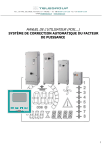
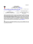
ELNESS SRL CRAIOVA
USER MANUAL
CT 400
POWER FACTOR CORRECTION
AUTOMATIC CAPACITOR BANK
TYPE QAR2
Pag. 1/8
Generalities
1.1. Destination
User Manual refers to low voltage automatic capacitor banks QAR2 type 3x400Vca,
50Hz, for polluted networks with higher current and voltage harmonics (where there is a
significant number of electronic loads as rectifiers, inverters, etc.) the capacitor banks are
equipped also with antiresonance (detunning) reactors. We shall refer to it as “capacitor
bank” or “equipment”.
1.
1.2. Symbolization
The symbolization represent a letter and numbers group with the following meanings:
QAR2 - -/ - - : manufacturer code
QAR2: Low voltage and power capacitor banks with detuned reactors.
-/ : total reactive power, in kvar
- : number of steps and reactive controller used type
1.3. This equipment is for indoor use, with following conditions:
- without corrosive agents, electricity conductor powder, explosive or dust atmosphere
(max. 1mg/cbm)
•
•
•
Ambient temperature
minim temperature – 10°C
maxim temperature + 40°C
medium daily temperature < + 30°C
•
medium annual temperature < +25°C
•
relative humidity < 80% la –20°C
•
climate zone: N
•
We recommend installing so that the equipment is protected from direct solar
radiation or other heat sources;
•
Indoor rooms must have a good ventilation. For ventilation must be used air
conditioner or exhaust system properly dimensioned with inlet air filter.
1.4. Manufacturing standard : EN 60439-1
1.5. Warning: It is mandatory that the beneficiary is informed of the contents of these
instructions before installing and operating equipment.Failure to comply will lead to
removal from the warranty.
2. DATA SHEET
2.1. Electric diagram: annex 2.
2.2. Main technical characteristics: annex 1
ELABORAT DE:
SC EL-ness srl Craiova
INTOCMIT: ing. L. Pufu
DATA: 07 05 2015
VERIFICAT:ing.S. Olar
DATA: 07 05 2015
POWER FACTOR CORRECTION
AUTOMATIC CAPACITOR BANK TYPE QAR2
Pag 2/8
2.3. Torque coupling assembly :
M6
M8
M10
M12
6Nm 15Nm 30Nm
55Nm
2.4. Lifetime: 15 years, compliance with user manual instructions.
CHECK THE RECEPTION EQUIPMENT
Before the installation, please check the following:
3.1. The equipment was not hit or damaged during transport.
3.2. Equipment supplied is the type ordered by you and is what you need.
3.3. Mains rated voltage is the same voltage specified on the equipment label
3.4. User manuals for capacitor bank and for reactive controller was delivered with
the equipment.
3.
4. DESCRIPTION
4.1. The equipment is included in a metallic enclosure to be fix on the sturdy floor.
The metallic part of enclosure is electrostatic painted with RAL 7035 color. The
enclosure have one front door.
4.2. Inside the enclosure there are:
1) Special capacitor contactors with leading inrush current limiting resistances;
2) Cylindrical aluminum case, low-loss, self healing with overpressure protection,
dry, gas, long life (>130.000h) capacitors;
3) Highly reliable automatic power factor regulator with voltage, current , PF and
current THD displays, alarms for overvoltage, over and under compensation;
4) Fuse switch disconnectors with NH fuses for groups of capacitors;
5) 7% three phase detunning reactors, vacuum impregnated, temperature protected;
6) Forced ventilation;
HOW IT WORKS
Please see the electric diagram -annex 2. Depending on the reactive power
consumption the automatic power factor regulator switches the contactors that
introduce capacitor steps just enough to provide the necessary reactive current. The
user must set the target of cos FI ( read the regulator manual).The default value of cos
FI is 0.98.
Between two same step connection the regulator waits for capacitors discharging
(reconnection time). Inputs requested:
- total load current from a current transformer …/5A (minim power 5VA) mounted
on L1 of three phase mains. We recommend that the current transformer must be
mounted alongside the current transformer of energy meter and must measure the total
current (loads+capacitor bank).
Warning: the capacitor bank does not include the current transformer!
5.
Pag 3/8
POWER FACTOR CORRECTION
AUTOMATIC CAPACITOR BANK TYPE QAR2
6.
LOCATION AND INSTALLATION
6.1. The capacitor bank must be installed on sturdy floor standing, away from sources
of heat. In fig. 1 you can see the output connections (to current transformer and supply
network):
To current
transformer
k, l/s1,s2
terminals
Load
To main
neutral
Capacitor bank
S1
S2
N
Capacitor bank
terminals
6.2. The connection to the mains of the capacitor bank should be made with copper
cable with 1000V isolation voltage and the section in complience with maximum
current input (see annex 1). Warning: the phase sequence connection must be from left
to right L1, L2, L3 and N terminal conductor will be copper cable with 4mm2
section.
6.3. The current input (equipment terminals S1, S2) comes from a current transformer
…/5A (minim power 5VA) mounted on L1 of the three phase mains. It will be used
only for the capacitor bank. The connection conductor from current transformer to
S1/S2 terminals will be copper cable with 2.5 mm2 section. If the distance to the
capacitor bank is more than 5 m, please use 4mm2 cable.
6.5. The capacitor bank metallic enclosure will be connected to ground belt with
copper cable with adequate section (see annex 1).
PREPARATION FOR COMMISSIONING AND OPERATION
7.1. Check (with ohmmeter) continuity of earthing circuit protection.
7.2. Check tightening screws to power and control terminals (contactors, separators,
capacitors terminals ).
7.3. Check base menu of automatic power factor controller and change the parameters
if needed (see DCRL5 instruction manual). Pay attention on P.01-CT primary, P.03
-CT read phase = L1, P.05-Voltage = L2-L3, P.06-smallest step power, etc. You can
see the default parameters in annex 1.
7.4. Check that the power fuse disconnectors are closed, then close control MCB. In
the beginning the pf controller displays loads power factor. This power factor must be
inductive, between 0.6-0.9. If enough loads are connected, the pf controller should
close enough capacitor steps, and power factor displayed increases up to target set. If
the power factor displayed is capacitive you must reverse cables in S1 and S2
terminals, then see the display. If now we have inductive power factor and the
equipment will begin to connect the capacitors, the installation is well done.
Disconnect some loads and check if power factor becomes capacitive and after that
the equipment will disconnect some steps. Finally the power factor will become
7.
POWER FACTOR CORRECTION
AUTOMATIC CAPACITOR BANK TYPE QAR2
Pag 4/8
close to target PF set. When there is no load connected to the mains, the equipment
must disconnect all steps (please check!).
PERIODIC MAINTENANCE
8.1. Maneuvering by unskilled and untrained personnel is prohibited! Working
personnel should wear appropriate protective equipment in working time and must
know the operating and installation instructions.
8.2. Operation of equipment with the doors open is forbidden.
8.3. All maintenance operations are performed by trained personnel (authorized
electricians for JT), without voltage (by disconnecting the bank supply breaker).
After disconnection wait 10 minutes, then check voltage at the terminals of
capacitors!
8.4. In the first month please check:
8.
- the supply voltage, especially during periods when the load is small
-
temperature inside the cabinet
visual the condition of capacitors, reactors, contactors and connection cables
measure the current through capacitors with a measuring device, should not
exceed 1.1xIn (see Annex 1).
- tighten loose connections from contactors, breakers, capacitors, coils (after
disconnecting the battery from the mains and after 10 minutes necessary for
discharging and checking the absence of voltage with a measuring device!)
8.5. Every day check the proper functioning of the capacitor bank by viewing the
information on the display controller: power factor value and possible alarms.
Check the controller has disconnected capacitor steps without loads (eg, upon
completion of the work program).
8.6. For forced cooled capacitor banks, the filters and the cabinet must be cleaned of
dust by vacuuming once a month. Change the filter if it is too clogged. This operation
is written in the maintenance sheet. Check weekly visual the dust and if exists
electrical metallic powders on bars, bars supports, devices (disconnectors, circuit
breakers, capacitors, contactors) and if it exists, clean the equipment. Check dust or
metal powders source and try to remove it.
8.7. Every four months check the status of electrical contacts of terminals circuit
breakers / disconnectors, coils, contactors and capacitors, tighten weakened
contacts or take measures to replace equipment or cable connection that shows
signs of damage (with excessive heating of the insulation, melting, etc.).Inspect for
soot stains on contactors and if there is, check the state of electric contacts. If
damaged, replace the contactor! Check the status of earthing connections with the
measure device!This operation is written in the maintenance sheet. Each month
see the electricity bill to check the proper functioning of the system. If this
notice the reactive energy (inductive or capacitive) in excess, contact the
installer for checking the battery.
POWER FACTOR CORRECTION
AUTOMATIC CAPACITOR BANK TYPE QAR2
Pag 5/8
9.MARKING, TRANSPORT, STORAGE, ACCOMPANYING DOCUMENTS,
DELIVERY COMPONENTS
9.1. Marking
product label includes:
- producing company name;
- the name and type of product ;
- year and the number of manufacturing ;
- rated parameters
9.2. Transport
The capacitor bank can be transported by trucks or by rail. During transport,
installation will be anchored properly, will not be hit, smashed and will be protected
from strong vibrations.
9.3. Storage
Storing at beneficiary will be in closed room, with climatic conditions described in
paragraph 1.3.
9.4. Accompanying documents
Manufacturer offers beneficiary the following technical documentation:
- electrical diagram
- capacitor bank user manual
- controller user manual
- warranty certificate and declaration of conformity
9.5. Delivery components
A complete delivery kit must content::
−
capacitor bank
−
accompanying documents
LABOR AND FIRE PROTECTION RULES.
10.1. Observe all working safety conditions and fire regulations stipulated in current
standards for low voltage installations.
10.2. All maintenance activities shall be made only after removing the power supply.
10.3. After the power supply is disconnected, wait for approx. 10 min. for capacitors
discharge
10.4. check with the voltmeter the capacitor terminals, must have no voltage!
10.5. After that you can do the work.
10.6. During the operation, cabinet door will be closed with special key that will be
kept by the maintenance electrician
10.
11. ENVIRONMENTAL PROTECTION
11.1. 15 years lifetime.
11.2.After the lifetime, capacitor bank will be delivered to recovery and recycled
materials companies.
11.3. Recoverable materials: steel enclosure, etc., copper cables, plastics;
11.4. All components of the materials comply with environmental standards.
POWER FACTOR CORRECTION
AUTOMATIC CAPACITOR BANK TYPE QAR2
Pag 6/8
11. TROUBLE SHOOTING TABLE
No
PROBLEMS
1 The display controller does not
light
2
3
4
5
6
CHECKS
1. The main breaker / separator and / or
command circuit breaker / separator is
OFF.
2. Power or command fuses and / or are
burned.
3. The supply voltage is no present at the
input terminals of the capacitor bank:
check with the voltmeter
After the power supply
1. Reverse terminals S1, S2 measure current
coupling, displayed PF (power
transformer connections
factor) is capacitive even if no
2. Check again phasing L1, L2, L3 to the
capacitor step is connected
input terminals and if CT (current
transformer) is mounted on phase L1.
When coupling power supply
1. The amount of power reactive required
the PF displayed is inductive but
is less than the value of the first stage
the capacitor bank doesn't insert
of the bank. You must turn on more
steps
loads (you can read the value of the
necessary reactive power displayed by
controller)
2. Inductive PF value is close to the
programmed value, it does not need
steps connection
When coupling power supply
1. CT (current transformer) was wrong
the PF displayed is inductive,
placed, measuring only the load
the capacitor bank insert steps,
current, don't measure total current
but PF displayed don't change
(load + bank current)
2. Capacitor bank power is much smaller
than required reactive power. Order a
biggest capacitor bank or make an
extension of the existing one
During start up, the display
1. There are no loads / consumers
doesn't show PF value,it
connected to the network or load
displays an alarm code and the
current value is very small.
capacitor bank does not connect
2. Check the alarm code significance in
steps.
user manual controller
PF displayed is inductive,
1. The capacitor bank is undersized, check the
capacitor bank connects steps,
display for reactive power required value and
PF value increases but does not order an extension.
reach the set value, with all the
2. Check fuses, could be burned
steps inserted into the circuit
3.
Check capacitors, may have less value
because of the burning of sections
4.
Check the condition of contactors, if
power contacts are in good condition
POWER FACTOR CORRECTION
AUTOMATIC CAPACITOR BANK TYPE QAR2
12. ANNEXES
- electrical diagram
- Technical information
Eng. Lucian Pufu
Pag 7/8
Pag 8/8
POWER FACTOR CORRECTION
AUTOMATIC CAPACITOR BANK TYPE QAR2
ANNEX 1
Capacitor banks type QAR2-200-5L
Technical information:
•
•
•
•
•
•
•
•
•
•
•
voltage supply:
control circuit voltage supply:
Total reactive power:
steps:
rated current:
maximum current (for electrical sizing
switches / connection cable):
dimensions:
weight:
degree of protection:
permissible short circuit current :
location :
3x400V, 50Hz
230V, 50Hz
200 kvar
2x25+3x50 kvar
289A
413.3A
1500x800x400mm
240 kg
IP 21
35 kA
indoor
Recommended values :
The copper single phase cable for power supply
The copper single phase cable for ground
connection
Breaker / fuse protection at starting power cable
Current transformer pre-setting value
PARTS LIST:
Capacitors, reactors
Symbol
Reactive
Rated
power/ voltage current
[kvar/ V]
[A]
C1,C2, 28kvar/440V
36.8
C3,C4,
C5,C6,
C7,C8
L1,L2 25kvar,400V,
43
189Hz,7%
L3,L4, 50kvar,400V,
86
L5
189Hz,7%
contactors
Symbol Reactive
power
[kvar]
K1, K2 25
K3, K4, 50
K5
Controller: type DCRL5,5 steps, LOVATO
150mm2/ phase
75 mm2
400A
400/5A
fuses
Symbol Current
[A]
F1,F2,
F3
160
Q01
4
POWER FACTOR CORRECTION
AUTOMATIC CAPACITOR BANK TYPE QAR2
AUTOMATIC CAPACITOR BANK
FOR POWER FACTOR CORRECTION
200kVAr/ 400V
type QAR2 200- 5L
ELNESS SRL, Craiova, Drumul Ungurenilor 6
Tel: +40251563113
Pag 9/8