1
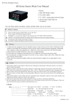
SD Series Intelligent Sensor
SD Series Sensor Meter User Manual
Features:
1. Dual line LED display,lower line display measuring value;
2. Two alarm output;
3. Accept different Analog signal or Temperature signal input;
For your safety, please read following content carefully before you are using our meter!
Safety Caution
*
Please read the manual carefully before you use the meter
Please comply with following inportant points:
WARNING: An accident may happen if the operation does not comply with the instruction
NOTICE: An operation that does not comply with the instruction may lead to product damage
The instruction of the symbol in the manual is as follow.
An accident or danger may happen in a special condition.
Warning
1. A safty protection equipment must be installed or please contact with us for the relative information if the
product is used under the circumstance• such as nuclear control, medical treatment equipment, automobile,
train, airplane, aviation and equipment etc.. Otherwise, it may cause serious loss, fire or person injury.
2. A panel must be installed, otherwise it may cause creepage (leakage).
3. Do not touch wire connectors when the power is on, otherwise you may get an electric shock.
4. Do not dismantle or modify the product. If you have to do so, please contact with us first. Otherwise it may
cause electric shock and fire.
5. Please check the connection number while you connect the power supply wire or input signal, in case
cause fire.
Caution
1. This product cannot be used outdoors. Otherwise the working life of the product will become shorter, or an electric
shock accident may happen.
2. When you connect wire to the power input connectors or signal input connectors, the moment of the No.20 AWG
(0.50 mm2) screw tweaked to the connector is 0.74n.m - 0.9n.m. Otherwise the connectors may be damaged or get fire.
3. Please comply with the rated specification. Otherwise it may cause electric shock or fire, and damage the product.
4. Do not use water or oil base cleaner to clean the product. Otherwise it may cause electric shock or fire and damage the
product.
5. This product should be avoid working under the circumstance that is flammable, explosive, moist, under sunshine, heat
radiation and vibration. Otherwise it may cause explosion.
6. In this unit it must not have dust or deposit, otherwise it may cause fire or mechanical malfunction.
7. Do not use gasoline, chemical solvent to clean the cover of the product because such solvent can damage it. Please use
some soft cloth with water or alcohol to clean the plastic cover.
2
1. Model
SD □ □□□□□
T:Temperature signal input
B:DC 24V Auxiliary Power A:DC 12V Auxiliary Power(be ordered)
Blank:No Auxiliary Power
10:Single Input
C:Two Alarm A:No Alarm
R:Relay Alarm output
4:48W×48H 6:48W×96H 7:72W×72H 8:96W×48H 9:96W×96H
80:160W×80H(be ordered) 16:80W×160H(be ordered)
KKSDE01-A/4-1
2.Model Description
Model
Input Signal
①SD□-A10(Normal Model)
DC 0~10V or 4~20mA(other signal be ordered)
②SD□-RC10B(Normal Model) DC 0~10V or 4~20mA(other signal be ordered)
DC 0~10V or 4~20mA(other signal be ordered)
③SD□-RC10A(be ordered)
No Alarm
Auxiliary Power
NO
TWO Relay Alarm
DC 24V/30mA
TWO Relay Alarm
DC 12V/30mA
Alarm Function
④SD□-A10-T(be ordered)
TC/RTD
No Alarm
⑤SD□-RC10B-T(be ordered)
TC/RTD
TWO Relay Alarm
NO
DC 24V/30mA
Special Notice:
1. ①②③ Model with 4-20mA or 0-10V signal input before EX-factory, customer who want to change the signal between
those two different signals, they should change “INP” menu (please refer to Setting Menu), and just change insert needle according to
following instruction: (EX-Factory setting is 0-10V input, if want to input 0-10V DC, there is no need to change the needle)
1 2 3 4 5
0-10V input: connect 2-7, 4-9; 4-20mA input: connect 3-8, 5-10 (with insert needle cap connect)
6 7 8 9 10
mV/R V mA V mA
2、④⑤ Model do not need to change the needle
3.Main Technical Parameters
±0.5%F.S
Measuring Accuracy
Alarm Output
Power Supply
Relay 1 output capacity: AC 1A/250V Relay 2 output capacity: AC 3A/250V
SD4: AC/DC 100~240V SD7:AC 110/220V±10% SD6/8/9/16/80:AC 220V±10%
Total Current
Ambient temperature
Ambient humidity
Auxiliary Voltage
<30mA(220VAC)
0~50℃
45~85%RH
24V 30mA (12V auxiliary voltage can be specially ordered)
4.Panel Indication
SD8 DIGITAL METER
AL1 output indication lamp
AL1
AL2 output indication lamp
AL2
Measurment Display
Display unit
Increase key
Decrease key
SET function key
Shift key
5. Panel Key Operation
▲
▲
▲
▲
(1). SET key: After power on, long time press SET key can enter into setting MENU; press SET key long time
agian can exit from MENU, press SET key for one time can enter into other branch menu.
(2). “ ” Key: in the each Menu, press Key, the value that need to be changed will flash, press Key or ▲ Key can
modify the parameter.
(3). “ ▲ ” Key: After press
Key, press ▲ Key or Key to modify the value, press ▲ Key or Key without move
your hand can quickly increase or decrease the value. After modification, press SET key for confirmation.
▲
▲
6.Operation Sequence
→
Power on
Measuring Status
AL1
AL2
AL1
#2 Alarm Mode
AL2
Celsius Degree / Fahrenheit Degree
④⑤ Model with this Menu,
①②③ Model do not with this Menu
AL1
AL2
→
SET
#2 Alarm
Hysteresis
AL1
#1 Alarm Value
AL2
→
→
SET
Press SET key for 3s
AL1
AL2
AL2
→
→
SET
SET
→
AL1
SET
AL1
#1 Alarm Mode
AL2
Input signal
choose
AL1
PV Bias
AL2
AL1
→
→
SET
AL1
AL1
AL2
·
AL1
·
AL2
→
#1 Alarm
Hysteresis
AL2
Display lowest limit
AL2
SET
SET
Filter Constant
AL1
→
→
SET
SET
#2 Alarm Value
AL2
AL2
→
Decimal point
selection
AL1
AL1
Display highest limit
AL2
SET
AL1
→
→
SET
SET
AL2
Menu lock password
KKSDE01-A/4-2
7.Setting Menu
Menu
Function name
Description
Setting range
Null、m ,cm ,mm ,Kg,g,mg,MPa,Pa,ba,
Mba,N,W,KW,RPM,HZ,KHZ,mV,V,KV,mA,A,KA,Ω,℃,
°F ,can be choosed
Under measuring
status lower line Measurement unit
choose
display
#1 Alarm Value
#1 Alarm Value Setting
AD1
#1 Alarm Mode
HH: Alarm 1 upper limit HL: Alarm 1 lower limit
HY1
#1 Alarm Hysteresis
#1 Alarm Hysteresis
#2 Alarm Value
AD2
HY2
/
No Unit Display
FL~FH
AL1
AL2
Ex-factory setting
200
HH
HH/HL
0-1000
1
FL~FH
#2 Alarm Value Setting
600
#2 Alarm Mode
HH: Alarm 2 upper limit HL: Alarm 2 lower limit
HH/HL
HH
#2 Alarm Hysteresis
#2 Alarm Hysteresis
0~1000
1
-1000~1000
0
1-250
20
0-3
0
C-F
C
PS
To bias meter display because of sensor
PV Bias
FT
Filter Constant
DP
Decimal point selection
Digital filter for input signal
Decimal point setting
CF
Temperature Unit
C:Celsius F:Fahrenheit Model ①②③ No this menu
FL
Display lowest limit
Display lowest limit setting
FH
Display highest limit
Display highest limit setting
INP
Input signal choose
LCK
Menu lock password
Model ①②③:
:0~10V;
:4~20mA;
Model ①②③:-1999~9999
-1999/-20
Model ④⑤:Input Table
Model ①②③:-1999~9999
4000/1300
Model ④⑤:Input Table
:0~50mV;
:0~400Ω
/
Model ④⑤:K J E T S PT100 CU50 CU100
/
0
0~250
Password setting, the menu was forbade change when setting “11”
Input Signal Table
Code
Input Type
K
J
E
T
S
PT100
CU50
CU100
Measuring Range
-20~1300℃
-20~1000℃
-20~600℃
-20~400℃
-20~1700℃
-199.9~610.0℃
-50.0~150.0℃
-50.0~150.0℃
8. Mounting Size
Resolution
1℃
1℃
1℃
1℃
1℃
0.1℃
0.1℃
0.1℃
Accuracy
Input Resistance
>100KΩ
>100KΩ
>100KΩ
>100KΩ
>100KΩ
(0.2mA)
(0.2mA)
(0.2mA)
0.5%F.S
0.5%F.S
0.5%F.S
0.5%F.S
0.5%F.S
0.5%F.S
0.5%F.S
0.5%F.S
Side Face Size
Front Size
A
Mounting Size
G +0.5
-0
C
E
D
H
J +0.5
-0
B
Model
K
F
C
D
E
F
G
H(Min)
J
K(Min)
48
97.5
6.5
91
45
45.5
25
45.5
25
48
96
97.5
9
88.5
89.5
45
25
90
25
72
72
97.5
9
88.5
67
67.5
25
67.5
25
8:(48*96)
96
48
97.5
9
88.5
44.5
90
25
45
25
9:(96*96)
96
96
97.5
9
88.5
91.5
92
25
92
25
80:(80*160)
160
80
96
13
83
75.5
155.5
30
76
30
16:(160*80)
80
160
96
13
83
155
76
30
155.5
30
A
4:(48*48)
48
6:(96*48)
7:(72*72)
Note
B
Unit:(mm) tolerance ±0.5%(except special marked)
KKSDE01-A/4-3
9. Connection Drawing
SD7
Power Supply:AC 110/220V±10%
Alarm Relay Output:AC 250V 1A
SD4 Power Supply:AC/DC 100-240V
Alarm Relay Output:AC 250V 1A
mV/TC
Rt/RTD
24V/30mA
24V/30mA
Rt/RTD
mV/TC
SD9
Power Supply:AC 220V±10%
Alarm Relay Output:AC 250V 1A
SD6/SD8
Power Supply:AC 220V±10%
Alarm Relay Output:AC 250V 1A
SD16/SD80
Power Supply:AC 110/220V±10%
Alarm Relay Output:AC 250V 1A
Note:Please subject to the drawing on the products as final if there is any different from the above
10.Simple Problem Shooting
Display Message
Display HHHH/LLLL
Shooting Method
To check input signal connection well or not.
To check FH, FL value;
To check working temperature is OK or not.
To check input signal selection is right or not.
KKSDE01-A/4-4