1
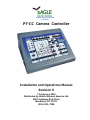
EAGLE
PAN TILT SYSTEMS
Helping to bring your world
into focus
PT-CC Camera Controller
Installation and Operations Manual
Revision 9
17 February 2014
Distributed by Hitachi Kokusai America Ltd.
150 Crossways Park Drive
Woodbury, NY 11797
(516) 921-7200
1
1. PRECAUTIONARY STATEMENT__________________________________ 3
2.WARRANTY__________________________________________________ 3
3. CONTROL PANEL_____________________________________________ 3
4. POWER REQUIREMENTS / PIN CONFIGURATION___________________ 6
2
The PT-CC camera control system allows the control of many cameras from Hitachi.
It is available in a standard desktop version, or an optional rack mount version. It provides
functional control of most camera features, and is similar in operation to the Hitachi RCC10 and RC-Z3 controller. The advantage of this controller over the other Hitachi controllers is that only one PT-CC control is needed to talk to all the cameras on the RS-485 line;
you don’t need an individual control for each camera as with the RC-C10 or Z3. The PT-CC
camera control only works in conjunction with the PT-C pan tilt control.
1.PRECAUTIONARY STATEMENT
Please read all of the following documentation before attempting the installation and configuration of these systems. If any of the instructions are unclear to you,
call your servicing dealer or Hitachi before proceeding for clarification. Failure to
correctly configure and install these systems may cause damage to the equipment,
and will void the warranties. Please make sure before connecting or disconnecting
any cables that the power supplies are turned OFF.
2.WARRANTY
Hitachi Kokusai America, Ltd. warrants to the original customer that each unit shall
be free from malfunction due to defective workmanship or component failure for a period of
ONE YEAR from the original date of delivery to the customer. For service under the warranty period, return authorization must be obtained before returning the product. This warranty
does not apply to finish or appearance items, to malfunction due to abuse or operation in violation of published operating specifications, or to failures caused by improper connections,
modifications, alterations, or other unauthorized repairs. This warranty does not cover labor
or shipping costs for removal and/or reinstallation of equipment under warranty. Under no
circumstances shall Hitachi Kokusai America, Ltd. or Display Devices, Inc., their owners or
employees be liable to you for any special damages, including any lost profits, lost savings,
or other incidental or consequential damages, or for any claim by any other party.
3.CONTROL PANEL
VERY IMPORTANT!! The cameras being controlled must have their communications speed set to 9600 baud for use with the PT-CC controller. Please set the speed in
accordance with your particular Hitachi cameras’ instructions. Please note that not all of the
features of the control panel may function with all cameras; for example shutter modes are
different depending on the camera being used.
The PT-CC control panel has red LED’s for status feedback of the current operation; these
LED’s are not illuminated when the system is first turned on from an OFF state. When
switching from one camera to another, the LED’s do not update status to reflect the true
state of the camera. The controller is only unidirectional; status of camera setup is not
returned to the panel from the camera when a button is pushed. The PT-CC merely sends
commands to the camera. In order to check the state of a function on the panel, you must
3
push one of the buttons to activate it. The LED will then show the status of the last command sent to the camera.
4.CONTROL PANEL— BUTTON FUNCTIONS
AUTO WHITE / AUTO BLACK
These buttons control the AUTO WHITE and AUTO BLACK features of the camera. Please
note that not all of the Hitachi cameras utilize these features in the same manner. Before
using the AUTO WHITE button, set the filter wheel on the camera to the closest lighting
condition; i.e., 3400K for indoor incandescent lighting, 5600K for outdoor lighting and indoor
fluorescent lighting. (NOTE: the filter wheel on some Hitachi cameras must be set using
the cameras’ MENU functions, as they have no physical filter wheel.) To use AUTO WHITE,
place a white card in the scene to be shot. The WHITE BAL setting must be in the MEM position. Zoom the camera in until the card takes up as much of the field of view as possible.
Press the AUTO WHITE button and the camera will automatically set the white balance for
the scene, and store it in the MEM position. To use the AUTO BLACK button, press it at any
time and the camera will close the lenses’ iris and set the black level properly.
SHUTTER
The SHUTTER button steps through the different shutter speeds (if so equipped) built into
the camera, starting at 1/60 second and stepping through the speeds back to OFF. Check
your user manual to see the speeds that the camera will cycle through. To enable the
variable speed shutter mode (Lock Scan), push the FUNCTION button, then the SHUTTER button. The LED over the SHUTTER button will flash quickly (about 3 Hz). Using the
up and down arrow keys, you may raise or lower the shutter speed to allow the cameras’
scan rate to be synced up with a computers’ CRT display. Please note that no display of
the shutter speed selected is available; you must adjust the speed by viewing the output
of the camera. Note that by holding the up key for several seconds will place the camera
into long term integration mode. To enable AES (automatic electronic shutter) mode, again
push the FUNCTION button, then the SHUTTER button. The LED will blink at a slower rate
(about 1 Hz) to show the camera is in AES mode. Push the shutter button again to turn off
the SHUTTER modes. Please see the feature chart at the end of this document for detailed
information specific to your particular cameras’ shutter operation modes.
CONTRAST
The CONTRAST button allows adjustment of the contrast enhancement features of the
camera (if so equipped). It will adjust the contrast of the scene in a looping fashion as long
as the button is held. To shut off the contrast adjustment feature, push the button again and
the LED will go out.
ULTRA GAIN
The ULTRA GAIN button turns on this camera feature (if so equipped). It adds a large
amount of gain to the picture with minimal extra noise to allow usage in very low light con4
ditions.
OPTION and FUNCTION:
These two buttons control different options on the camera depending on the model of camera being controlled. With most of the Hitachi cameras, pressing the OPTION button turns
on the on-screen menu of the cameras. The up, down, left, and right buttons will then allow
you to adjust the various fields of the camera menu. Press OPTION again to leave the set
up mode.
Press FUNCTION, then OPTION to enter the SPECIAL SET menu of those cameras. Similar operations may be carried out with some of the other models of Hitachi cameras.
PRESET
This button recalls SCENE files from memory for easy use by the camera operator. Follow
the instructions below to STORE the SCENE information. To recall the SCENE information,
press the PRESET button, then the number of the SCENE file to recall, 1 through 4.
STORE
This button takes the current settings selected on the control panel and stores them in the
PT-CCB camera control module located in the pan tilt head. This is for use with Hitachi
cameras having the SCENE file system. Users may make combinations of adjustments
and save them in SCENE files to be recalled quickly. To use this function, make any adjustments to the camera control as desired. Press the STORE button, then the file location to
store the SCENE info into, 1 through 4. This will store the information in the camera control
module for future recall. To recall the SCENE information, simply press the button number
of the SCENE file to recall, 1 through 4.
NOTE: When using the Hitachi cameras; pressing FUNCTION then STORE will store any
settings selected on the PT-CC and place them into memory as the initial power up settings
for the camera. This is useful for setting things such as white balance, phasing, etc.; the
mode that you would like the camera to power up in.
REMOTE—LOCK ON / OFF
The two buttons LOCK ON and LOCK OFF disable or enable all of the buttons on the
control panel. This is to prevent unauthorized changes to the camera settings or accidental
bumping of buttons.
BAR/CAM
This button is a toggle type button between normal camera operation and the built in color
bar generator of the camera. Pushing the button illuminates the LED of the function of the
camera (either BAR or CAM )
WHITE BAL
This button is a toggle type button between the three white balance modes. The PRESET
5
setting pulls up factory predetermined white balance values depending upon the setting of
the cameras’ filter wheel. The MEM setting is the user adjustable memory position. When
set to this mode, in conjunction with the AUTO WHITE button, user white balance settings
may be stored in the cameras’ memory. The AUTO setting is the automatic color balance
position; depending on the field of view of the lens, the camera will try to make the white
balance correct automatically.
GAIN DB
This is another toggling button that shifts between the different electronic gain modes on
the camera; the LED provides feedback for the different settings. Depending on the model
of the camera, these may not reflect the true level of gain. For instance, on most cameras,
the LED’s show the correct levels. On the HV-D15 however, the camera does not have
steps of gain like the other; it has GAIN MAX, GAIN HIGH, and OFF. The GAIN MAX and
GAIN HIGH settings are made through the on screen menu feature in the camera, and the
controller simply calls them up. On the PT-CC controller, the +18 and +9 settings reflect
GAIN MAX, the +6 and +3 settings GAIN HIGH, and 0 is OFF.
IRIS
This button toggles through the iris control modes on the camera; AUTO will let the camera
set the iris level dependent on the scene lighting. REMOTE enables the IRIS control buttons on the right side of the PT-CC control; pressing up arrow will open the iris, pressing
down arrow will close the iris. The MANUAL setting would be used for lenses without electronic iris control when the lenses’ iris ring must be set manually.
DTL
This button is a toggle between the different detail enhancement modes of the camera (
if your camera has this feature); the LED provides feedback for the different settings. The
VAR setting allows the recall of the variable detail mode that can be set in the menu of
some of the Hitachi cameras.
M BLK
These up and down buttons allow adjustment of the master black level settings of the camera; up arrow will raise the pedestal level, down arrow will lower the pedestal level.
H PHASE, SC COARSE, SC FINE, R&B GAIN, R&B BLACK
These buttons allow the setup of the camera, in conjunction with a waveform monitor and/
or vectorscope. Use the SELECT button to toggle between the different adjustments; use
the up and down arrow buttons to change the settings. The LOCK button prevents unauthorized changing of the settings.
4.POWER REQUIREMENTS / PIN CONFIGURATION
The PT-CC controller draws its’ power from the PT-C pan tilt controller via the DB-9 con6
nector on the rear panel. The connecting cable is included with the controller; only pins 1
thru 6 are used in a straight through configuration if the cable is lost and must be replaced.
7