1
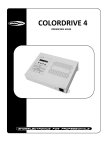
Ter
r
aLED
36CM
T
4.8 DIMMER
ABLE OF CONTENTS
MENU
DIMMER
OFF
DIM1
DIM2
DIM3
PART 1 PRODUCT (GENERAL)....................................................1.
1.1--PRODUCT INTRODUCTION.........................................................1.
1.2--PRODUCT FEATURES.................................................................1.
1.3--TECHNICAL SPECIFICATIONS.....................................................1.
1.4-- PHOTOMETRIC DATA ..................................................................2.
1.5--SAFETY WARNING......................................................................2.
DIM4
DIMMER
Enter the DIMMER to select the dimmer work mode, press Enter
When Dimmer is set to OFF the RGB and Master Dimmer are linear,
When selecting DIM1 , DIM2 , DIM3 or DIM4 ,the RGB and Master Dimmer
are nonlinear
These4 dimming modes have different soft and smooth dimming effects from fast to slow
PART 2 INSTALLATION...............................................................3.
2.1--MOUNTING...................................................................................3.
2.2--WIRING DIAGRAMS......................................................................4.
2.3--ADJUST THE BEAM ANGLE ......................................................... 4.
2.4--POWER CONNECTIONS............................................................... 5
.
2.5-- SIGNAL CONNECTIONS...............................................................5.
2.6-- SETTING UP WITH A DMX512 CONTROLLER ............................... 6.
2.7-- SETTING UP WITH THE PiX CONTROLLER................................... 6.
4.9 STATIC
MENU
PART 3 CONTROL WITH A DMX512 CONTROLLER.......................7.
3.1--CHANNEL ASSIGNMENT............................................................. 7.
3.2--BASIC INSTRUCTIONS FOR DMX512 OPERATION....................... 9.
PART 4 USING THE DMX CODER ................................................10.
4.1-- TECHNICAL SPECIFICATIONS ..................................................10.
4.2--SETTING PARAMETERS ........................................................... 10.
4.3-- BASIC ......................................................................................11.
4.4-- MENU ...................................................................................... 11.
4.5-- DMX ADDRESS ........................................................................ 12.
4.6-- PERSONALITY ......................................................................... 1
2.
4.7-- CALIBRATION .......................................................................... 12.
4.8-- DIMMER .................................................................................. 13.
4.9--STATIC.....................................................................................13.
STATIC
Gren
Blue
(0~255)
(0~255)
(0~255)
Str b
(0~20)
Red
STATIC
STATIC mode to create the programs
Enter the
Combine
RED , GREEN and BLUE to create an infinite
range of colors
Set the value of the STROBE
0-20Hz
The static setting will be valid when the fixture is powered again
PART 5 APPENDIX.....................................................................14.
5.1--TROUBLE SHOOTING...............................................................14.
5.2--MAINTENANCE......................................................
.................. 14.
4 USING THE DMX CODER
13
2009.7.21
4.5
DMX ADDRESS
MENU
DMX
1 PRODUCT (GENERAL)
(1~512)
1.1
PRODUCT INTRODUCTION
DMX
This product is designed for outdoor architectural applications. It
single unit and in multiple units for large applications.
Enter the DMX
mode to set the DMX address, press Enter
On successful setting, the fixtures will display Green and turn off after ten seconds
If an error occurs when setting, the fixtures will display Red or no response
1.2
4.6
PERSONALITY
MENU
can be operated both as a
PRODUCT FEA TURES
LED FIXTURE
PERSON
* RGB dimmer 0-100%
* Color macro
* RGB calibration
* Strobe
* Dimmer speed control
* Static Function
* DMX512 control
* Compatible with the PiX Controller
* Lightweight aluminum casing
* IP67 protection rating
ARC 1
ARC 1+D
ARC FULL
REMOTE
SOLID
PERSON
Enter PERSON and select
ARC 1 / ARC1+D / ARC FULL / REMOTE /
SOLID mode, press Enter
When selecting ARC 1 / ARC1+D / ARC FULL / SOLID , the fixture is under the
DMX work mode.
When selecting REMOTE , the fixture is ready to receive signals from the PiX Controller
1.3
TECHNICAL SPECIFICATIONS
LED MODULE
4.7 CALIBRATION
MENU
LED MODULE:
CALIB
WHITE 1
Red
WHITE 2
Gren
Blue
Voltage
(0~255)
(0~255)
(0~255)
Rated Power
IP
LED/Unit
WHITE11
RGB
Output/LED
Environment Temperature
CALIB
Cooling
Enter the CALIB to select white colors of different color temperature
There are 11 pre-programed white colors plus RGB and can be edited by using Red ,
Gren , or Blue ,press Enter to set the values
While working under ARC FULL , WHITE1-9 means the different color
temperature white 1 to white 9 of CH5
Select RGB to set the ratio of
Red , Gren , and Blue on DMX channels,
achieving different white colors
4 USING THE DMX CODER
12
2009.7.21
Dimensions
Weight
1 PRODUCT(GENERAL)
AC100~240V...50/60Hz
46W
IP67 PROTECTION RA TING
12pcs (tri-color)
3W
-20
~40
Direct air convection
320 x146mm
8Kg
1
2009.7.21
4.3
PHOTOMETRIC DATA
RED
159
71
41.3
2
4
6
8
10Distance(m)
BLUE
68
31
18.5
0
2
4
6
8
155
163
96
2
4
6
8
13 LUX
2242
555
252
149
10Distance(m)
0
2
4
6
8
BASIC
POWER Power on
MENU
Scroll through the main menu or exit from the
current sub-menu (press and hold to turn off power)
ENTER Enter the currently selected menu or confirm
the current function value
DOWN Scroll 'DOWN' through the menu list or decrease
the value of the current function
UP
Scroll 'UP' through the menu list or increase the
value of the current function
67 LUX
10Distance(m)
RGB
15
227
1240
0
15
0
GREEN
28 LUX
15
801
102 LUX
15
1.4
POWER
UP
10Distance(m)
MENU
ENTER
DOWN
1.5
SAFETY WARNING
IMPORTANT
4.4
ALWAYS READ THE USER MANUAL BEFORE OPERATION.
PLEASE CONFIRM THAT THE POWER SUPPLY STATED ON THE PRODUCT IS THE
SAME AS THE MAINS POWER SUPPLY IN YOUR AREA.
MENU
MENU
DMX
(1~512)
PERSON
ARC 1
ARC 1+D
ARC FULL
This product must be installed by a qualified professional.
Always operate the equipment as described in the user manual.
A minimum distance of 0.5m
must be maintained
between the equipment
and
combustible surface.
The product must always be placed in a well ventilated area.
Always make sure that the equipment is installed securely.
DO NOT stand close to the equipment and stare
directly into the LED light source.
Always disconnect the power supply before attempting maintenance.
Always make sure that the supporting structure is
solid and can support the combined
weight of the products.
The earth wire must always be connected to the ground.
Do not touch the power cables
if your hands are wet.
REMOTE
SOLID
CALIB
WHITE 1
Red
WHITE 2
Gren
Blue
(0~255)
(0~255)
(0~255)
WHITE11
RGB
DIMMER
ATTENTION
OFF
DIM1
DIM2
DIM3
DIM4
STATIC
This product left the place of manufacture in perfect condition. In order to maintain this
condition and for safe operation, the user must always follow the instructions and safety
warnings described in this user manual.
Avoid shaking or strong impacts to any part of the equipment.
Make sure that all parts of the equipment are kept clean and free of dust.
Always make sure that the power connections are connected correct and secure.
If there is any malfunction of the equipment, contact your distributor immediately.
When transferring the product, it is advisable to use the original packaging in which the
product left the factory.
Shields, lenses or ultraviolet screens shall be changed if they have become damaged to
such an extent that their effectiveness is impaired.
The lamp (LED) shall be changed if it has become damaged or thermally deformed.
1 PRODUCT(GENERAL)
2
2009.7.21
4 USING THE DMX CODER
Gren
Blue
(0~255)
(0~255)
(0~255)
Str b
(0~20)
Red
11
2009.7.21
4 USING THE DMX CODER
4.1
2 INSTALLATION
2.1
TECHNICAL SPECIFICATIONS
Embed the outer casing first before installing the fixture.
LED MODULE:
Battery
Dimensions
Weight
4.2
MOUNTING
2 x 1.5V DC
110 x 70 x 28mm
0.2Kg
SETTING PARAMETERS
NOTE: The stainless steel cover should
not exceed the ground..
Connect the DMX Coder to the units in series
Set the DMX address, Personality, Calibration and Dimmer of fixtures through the DMX
Coder
A maximum of 20 units in series can be set by the DMX Coder at the same time
All connected units will be set with the same information
NOTE: When installing the collar,
ensure that one of the cable outlets
is perpendicular to the target
illumination surface.
............
Power
Concrete
DMX-OUTPUT
Drainpipe
1 - GND
2 - Data
3 - Data
+
Hardpan
1 .GND
Black
2. Data-
Green
3. Data+
Red
Signal Connector
Note: The DMX Coder will automatically power
(1 minute)
4 USING THE DMX CODER
10
off after extended
periods of being
The fittings have been designed and
tested to withstand a static load of
3000kg(based on the outer casing) for
installation exclusively in
pedestrian or
bicycle areas.
idle
2009.7.21
2 INSTALLATION
3
2009.7.21
2.2
WIRING DIAGRAMS
3.2
Unscrew the junction box and remove the cover. Fetch the terminal for cable connection.
Put the cable( 6.5~8mm) throught the junction box.
Tighten the terminal with the cable according to the instruction.
Screw the junction box.
BASIC INSTRUCTIONS FOR DMX512
OPERATION (ARC FULL)
MASTER DIMMER
CH1 controls the intensity of the currently projected color
When the slider is at the highest position (255) the intensity of the output is the maximum
30 mm
10 mm
RED, GREEN & BLUE COLOR SELECTION
CH2, CH3 & CH4 control the intensity ratio of each of the RED, GREEN, BLUE LEDs
When the slider is at the highest position (255) the intensity of the color is the maximum
CH2, CH3, CH4 can be combined together to create over 16 million colors
COLOR MACROS
CH5 selects the required COLOR MACRO
CH5 has priority over CH2, CH3, CH 4
CH1 is used to control the intensity of the COLOR MACRO
Nut
Terminal
STROBE
CH 6 controls the strobe of CH1 to CH 5
Data GND
2.3
Live BLACK#18
BLACK#22
Data -
GREEN #22
Data +
RED #22
GND
L
D-
E
D+
N
Earth
Neutral
DIMMER SPEED
CH 7 is used to select the kind of dimmers curve required
GREEN #18
WHITE #18
ADJUST THE BEAM ANGLE
NOTE: The bolts that secure the frame to the body must be fully tightened in a uniform
manner, altermating between diametrically oposed bolts. To facilitate the extraction of the
glass without damaging the seal fitted onto the frame, unscrew all the nuts except for two
adjacent ones and wait a few seconds; then unscrew the remaining nuts and remove the
glass.
2 INSTALLATION
4
2009.7.21
3 CONTROL WITH A DMX512 CONTROLLER
9
2009.7.21
CHANNEL
VALUE
2.4
FUNCTION
POWER CONNECTIONS
51
70
RED 0%/GREEN100%/BLUE UP
71
90
RED 0%/GREENDOWN/BLUE 100%
91
110
RED UP/GREEN 0%/BLUE
111
130
RED 100%/GREEN 0%/BLUE DOWN
131
150
RED 100%/GREEN UP/BLUE
151
170
RED DOWN/GREEN DOWN/BLUE
171
200
RED 100%/GREEN 100%/BLUE 100%/WHITE 100%
201
205
WHITE 1: 3200K
206
210
WHITE 2: 3400K
211
215
WHITE 3: 4200K
216
220
WHITE 4: 4900K
Pins a nd Fun ction s
221
225
WHITE 5: 5600K
It is advised for greater stability that if over 20 units to be connected, or
the total signal
cable length is over 60 meters, a DMX signal amplifier should be used.
226
230
WHITE 6: 5900K
231
235
WHITE 7: 6500K
236
240
WHITE 8: 7200K
241
245
WHITE 9: 8000K
246
250
WHITE 10: 8500K
251
240
WHITE 11: 10000K
The input wires of this product must tri-core ,as folowing :
............
100%
UP
L
100%
N
L Black
N White
E Green
E
POWER
L
Junction box
5
2.5
0
10
9
255
Junction box
............
Pin1
Pin2
Pin3
Pin1
Signal out
Pins
Pin1 black
Pin2 green
Pin3 red
FROM SLOW TO FAST
Return to DIMMER
10
29
OFF (Dimmer speed off)
7
30
69
DIM1 (Speed 1, the fastest)
70
129
DIM2 (Speed 2)
130
189
DIM3 (Speed 3)
190
255
DIM4 (Speed 4 ,the slowest)
Pin3
Junction box
Junction box
NO FUNCTION
9
Pin2
Signal IN
DIMMING SPEED
0
L Black
N White
E Green
E
SIGNAL CONNECTIONS
STROBE
6
N
Functions
Gnd/0
Data input
Data input
+
SOLID
CHANNEL
1
VALUE
0
255
FUNCTION
RGB & MASTER DIMMER
3 CONTROL WITH A DMX512 CONTROLLER
8
2009.7.21
2 INSTALLATION
5
2009.7.21
2.6
3 CONTROL WITH A DMX512 CONTROLLER
SETTING UP WITH A DMX512 CONTROLLER
3.1
Connect the units in series,using standard DMX cable or IP 67 cable provided
Set DMX address using a DMX coder
Each DMX Address may be used as many times as required
Any DMX address in the range from 001 to 512 may be used
Connect the DMX512 controller to the units
DMX Addr.1
DMX Addr.8
CHANNEL ASSIGNMENT
Note: This product has five DMX512 channel configurations:
ARC FULL , SOLID .
DMX Addr.15
ARC 1
, ARC 1+D
,
ARC 1
............
CHANNEL
VALUE
FUNCTION
1
0
255
RED
2
0
255
GREEN
3
0
255
BLUE
Power
DMX512
CONTROLLER
The figure above shows a simple DMX512
layout with the starting address of the first
unit set at 1, with the second set at 8 and
so on...
ARC 1+D
CHANNEL
2.7
SETTING UP WITH THE PiX CONTROLLER
The fixture can also be controlled by the PiX Controller, set the fixture as
via the DMX coder before using the PiX controller
VALUE
1
0
255
MASTER DIMMER
2
0
255
RED
3
0
255
GREEN
4
0
255
BLUE
REMOTE
ARC FULL
Note: For details, please refer to the user manual of the PiX controller
CHANNEL
............
Power
VALUE
FUNCTION
1
0
255
MASTER DIMMER
2
0
255
RED
3
0
255
GREEN
4
0
255
BLUE
0
10
NO FUNCTION
11
30
RED 100%/GREEN UP/BLUE
50
RED DOWN/GREEN 100%/BLUE
PiX Controller
COLOR MACRO
5
31
2 INSTALLATION
FUNCTION
6
2009.7.21
3 CONTROL WITH A DMX512 CONTROLLER
7
0%
0%
2009.7.21