1
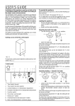
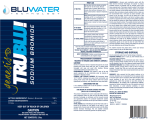
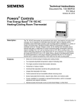
INTRODUCTION
Screens
Your 5330X-401/402 is a counter with an eight-digit LCD
display. A programmable scaler and decimal point allow
for display in any engineering unit.
There are four program-mode screens in the 5330X-401/
402. Upon entering the setup mode, the counter will display screen 1. Press and hold the
edly pressing the
screens.
Front View
Plastic
front panel
sealed to
m eet
NEMA 4X
Screen
1
2
3
4
RST
Reset/
Program ming
Button
Program ming
Button
Add/Subtract Counting
RST 4
Reset Inpu t
7 +10 -30 VD C
IN A 3
Q u adrature A
6 D C C om m on
IN B 2
Q u adrature B
GND 1
G rou nd
5 5E nable/R
E nable/R
There are two count input terminals on the rear of the totalizer. Count pulses entering Input A (terminal 3) cause the
total to decrement (count down). Count pulses entering
Input B (terminal 2) cause the total to increment (count up).
The totalizer may start counting from zero, when reset, or
may start from a user-programmed offset value. The offset
value is a positive number and may be up to six digits.
APPLICATIONS
If only one of the count inputs is used, the totalizer becomes an up counter with a range of zero to 99,999,999, or
a down counter with a range of zero to -9,999,999. If both
inputs are used, the totalizer displays the difference count
between the two inputs - counts at Input B are added, counts
at Input A are subtracted. In this mode of operation, the
totalizer’s range is -9,999,999 to 99,999,999. Positive numbers are not indicated with a plus sign(+). Both inputs may
occur simultaneously, in which case the displayed total
does not change.
Certain programming and wiring choices must be made to
accomplish your application. We recommend the following sequence:
1.
2.
Answer the following questions:
• What type of sensor will be used?
• To what engineering units should the counter be
scaled?
• How many pulses per item is the sensor
providing?
• Is a decimal point needed on the display?
Count Inputs
Calculate the scale factor.
Model 5330X-401 has hi-speed inputs and can accept
pulses from solid state, current sourcing sensors at up to
10 kHz per input. The sensor must supply at least +2.0
VDC, but not more than +24VDC to the input. Counts are
entered on the positive-going edge of the pulse.
MOUNTING
2.677" (67mm)
Recommended
Panel Cutout
1.299"
(33mm)
Model 5330X-402 has low speed inputs and can accept
pulses from solid state, current sinking sensors or contact
closures to ground at up to 20 Hz per input. These inputs
are internally pulled up to +3 VDC. The sensor must be
capable of sinking current from the input to bring the input
voltage down to +0.4 VDC or less. Counts are entered on
the negative-going edge of the pulse.
Gasket Installed?
Durant
Durant
®
Function
Count Scale Factor
Count Decimal Point
Reset to Offset Value
Reset Key Enable / Disable
OPERATION
Rear View
P rogram
E nable
key to advance to successive
Programming Screens
8-digit LCD
Display
Durant ®
key while repeat-
Install mounting clip
PROGRAM MODE
To enter the program mode, a connection must be made
between terminals 1 and 5 (see page 3).
1
COUNT SCALER
The far right digit will be flashing. Press the
reaching the desired digit value.
Calculating the Count Scale Factor
The count scale factor is used to convert the incoming count
pulses to the desired unit of measure to be displayed (feet,
gallons, etc.) or to correct for a known amount of error (wheel
wear, viscosity, etc.). This scaler has six digits available
with a fixed decimal point.
Note: Pressing and holding the
numbers to autoscroll.
Count Scaler Range: 0.0001 to 99.9999. (Setting the count
scale factor to 0.0000 will allow scaling by 100 in the Courier Series).
the RST
correctly.
RST
RST
key until
key will cause the
key to move the flashing digit one
Next press the
place to the left. Change this digit to the desired value with
key. Repeat this process until all digits are set
Programming Decimal Point
Count Scaler (CS) Formula:
The second screen is used to enter the decimal point display on the totalizer screen. Press and hold the
CS =
DPF
PPI
where:
and then press the
screen two.
key
key to move from screen one to
RST
DPF is the decimal point factor corresponding to the desired decimal point location.
DISPLAY
DPF
XXXXXX = 1
XXXXX.X = 10
XXXX.XX = 100
DISPLAY
DPF
XXX.XXX = 1,000
XX.XXXX = 10,000
Durant
Press the RST
sired position.
PPI is the number of pulses per item from the sensor.
Example 1: A sensor produces 20 pulses per inch of material travel. Calculate the count scaler required to indicate
material used in whole inches (XXXXXX).
CS =
1
20
100
120
RST
key to move the decimal point to the de-
Programming Offset Value
Programming an offset value allows the counter to reset to
a value other than zero. The offset may be up to six digits.
The offset cannot be a negative number.
= 0.05000
The third screen in the program mode is used to enter the
offset value.
Example 2: An encoder produces 120 pulses per foot.
Calculate the count scaler required to indicate material
usage in 1/100’s of feet (XXXX.XX).
CS =
®
= 0.83 33
Durant
®
RST
(Select the XXXX.XX position on the totalizer decimal point
menu).
The far right digit will be flashing. Press the
reaching the desired digit value.
Programming Count Scale Factor
The first screen in the program mode is used to enter the
count scale factor:
Note: Pressing and holding the
numbers to autoscroll.
RST
RST
key until
key will cause the
Next press the
key to move the flashing digit one
place to the left. Change this digit to the desired value with
Durant
®
the RST
correctly.
RST
2
key. Repeat this process until all digits are set
Enabling the Front Panel Reset Key
WIRING DIAGRAMS
Solid State Add/Subtract Input (53300-401)
The fourth screen in the program mode allows the user to
enable or disable the front panel reset key.
Durant
®
Current Sourcing Sensor
RST
Solid State Add/Subtract Input (53300-401)
Current Sinking Sensor
Press the
RST
key to choose the option you want.
+6 +2 8 V D C
1.5kΩ
RST 4
7 + 10-30V D C
Note: The reset terminal on the rear panel is still active
when the front reset button is disabled.
IN A 3
6 D C C om m on
IN B 2
GND 1
5 E5nable/R
E nable/R
To exit the program mode, break the connection between
terminals 1 and 5.
C urrent Sinking
S ensor
Contact Closure Count Input (53300-402)
WIRING RECOMMENDATIONS
RST 4
Following these suggestions will increase noise immunity
and lengthen unit life.
Cable: The connection between the count source and the
ratemeter should be made with a two-conductor shielded
cable. The shield should be connected to earth ground at
one end only. The connecting cable should not be run in
conduits with cables switching high inductive loads.
7 + 10 -30 VD C
IN A 3
6 D C C om m on
IN B 2
5 E5nEable/R
n able/R
GND 1
Program Mode Enable & Backight Wiring
RST 4
7 + 10-3 0V DC
IN A 3
6 D C C om m on
IN B 2
+
Relay Coil Suppression: If a relay contact is used as a
count source, the relay coil should be suppressed. This
can be accomplished with an RC network for AC coils or a
diode for DC coils. The Durant RC suppressor (38091400) may be used.
5 5E nab
le/R
E nab
le/R
GND 1
Remote Reset (All Models)
RST 4
Mounting: The totalizer should not be mounted near a
solenoid or other inductive devices. Enough ventilation
should be supplied to keep the ratemeter operating within
the temperature specifications. Do not mount this unit in a
heavy vibration area.
7 + 10-30V D C
6 D C C om m on
5 5E na
ble/R
E na
ble/R
IN A 3
IN B 2
GND 1
BATTERY SAFETY
Term inal
The lithium battery that powers your device contains inflammable materials such as lithium organic solvent, and
other chemical ingredients. Explosion or fire may result if
the battery is not handled correctly. To avoid an accident
follow these guidelines:
*
*
*
*
Func tion
O peration
1
G ro und
2
Inp ut B
C urrent S ource Inpu t (401)
C oun t Inpu t
C urrent S ink In put (402 )
Inp ut A
C urrent S ource Inpu t (4 01)
C oun t Inpu t
C urrent S Ink Inpu t (4 02)
4
R es et
C onn ect through C onta ct C losure
5
Prog ra m
C onn ect to G round to En ter
En able
Prog ra m M od e
3
to G round
Do not heat batteries above 95°C
Do not recharge lithium batteries
Do not dispose of batteries in fire
Insert battery with correct polarity
6
Ba ck light
C om m on
7
3
Ba ck light
C onn ect to P ow er to
Po w er
Light D isp lay
OTHER COURIER SERIES PRODUCTS
REPLACEMENT PARTS
36367-202
Battery
46066-210
Gasket
53300-241
Mounting Clip
28772-200
Mounting Screw
53300-400
53300-403
53300-404
53300-405
53301-400
53301-401
COURIER SERIES ACCESSORIES
49750-400
Power Supply (+15VDC, 300 mA)
38091-400
Count Source RC Suppressor
53301-402
Devices Requiring External Power for Proper Operation
48770-401, -402 Inductive Proximity Sensor (8mm,
12mm, 18mm)
48771-400
Diffuse-Reflective Photoelectric Sensor
48771-401
Retro-Reflective Photoelectric Sensor
48771-402
Thru-Beam Photoelectric Sensor
Emitter
48771-404
Thru-Beam Photoelectric Sensor
Receiver
(Thru-beam emitter and receiver must
be used together)
38151-XXX
Standard Duty, Quadrature Shaft
Encoder (XXX denotes pulses per
revolution. Example: 38151-060 for
60 pulses/rev).
48371-XXX
Heavy Duty, Quadrature Shaft
Encoder (XXX denotes pulses per
revolution. Example: 48371-060 for 60
pulses/rev).
53301-404
53301-405
53302-400
53302-401
53302-402
53302-404
53302-405
WARRANTY: Eaton warrants all products against defects in material and workmanship for a period of one (1) year from the date of
shipment to Buyer. This is a limited warranty limited to its terms.
This warranty is void if the product has been altered, misused,
taken apart or otherwise abused. ALL OTHER WARRANTIES,
EXPRESS OR IMPLIED, ARE EXCLUDED, INCLUDING BUT NOT LIMITED TO THE IMPLIED WARRANTIES OF MERCHANTABILITY AND
FITNESS FOR PURPOSE.
Totalizer
Quadrature Indicator/Totalizer
Ratemeter
Totalizer/Ratemeter
Totalizer - Extended Temperature
Add/Subtract Totalizer
(Solid State Input)
Add/Subtract Totalizer
(Contact Input)
Ratemeter - Extended Temperature
Totalizer/Ratemeter
Extended Temperature
Totalizer w/Backlight
Add/Subtract Totalizer w/Backlight
(Solid State Inputs)
Add/Subtract Totalizer w/Backlight
(Contact Inputs)
Ratemeter w/Backlight
Totalizer/Ratemeter w/Backlight
Moss Warranty Act (P.L.93.637), as now in effect or as amended
hereafter. The warranties and remedies provided for herein are
available to Buyer and shall not extend to any other person.
COMPLIANCE WITH OSHA: Eaton offers no warranty and makes
no representation that its products comply with the provisions or
standards of the Occupational Safety and Health Act of 1970, or
any regulations issued thereunder. In no event shall Eaton be liable
for any loss, damages, fines, penalty or expense arising under
said ACT.
BUYERS REMEDIES: Eaton’s obligations and liabilities under the
foregoing warranty are limited to repair or replacement of the
product without charge. To receive the required Return Goods
Authorization number (RGA), contact your local Durant distributor
or call 800-410-2910. A charge is made for repairing after the
expiration of the warranty. IN NO EVENT SHALL EATON BE LIABLE
FOR CLAIMS BASED UPON BREACH OF EXPRESS OR IMPLIED
WARRANTY OR NEGLIGENCE OR ANY OTHER DAMAGES
WHETHER DIRECT, IMMEDIATE, FORESEEABLE, CONSEQUENTIAL
OR SPECIAL OR FOR ANY EXPENSES INCURRED BY REASON OF
THE USE OR MISUSE, SALE OR FABRICATION OF PRODUCTS
WHICH DO OR DO NOT CONFORM TO THE TERMS AND CONDITIONS OF THIS CONTRACT.
This manual constitutes proprietary information of Eaton Corp.,
and is furnished for the customers’ use in operating the Durant
counter. Reproduction of this material for purposes other than the
support of Durant counters or related products is prohibited without the prior written consent of Eaton Corp., Watertown, WI.
In the construction of the Control described herein, the full intent of
the specifications will be met. Eaton Corp., however reserves the
right to make, from time to time and without proper written notice,
such departures from the detail specifications as may be required
to permit improvements in the design of the product.
INDEMNIFICATION: Buyer agrees to hold Eaton harmless from,
defend, and indemnify Eaton against damages, claims and expenses arising out of subsequent sales of Durant products or
products containing components manufactured by Eaton and based
upon personal injuries, deaths, property damage, lost profits, and
other matters for which Buyer, its employees or sub-contractors
are or may be to any extent liable, including without limitation penalties imposed by the Consumer Product Safety Act (P.L.92-573)
and liability imposed upon any person pursuant to the Magnuson-
The information included herein is believed to be accurate and
reliable; however no responsibility is assumed by Eaton Corp., for
its use; nor for any infringements of patents or other rights of third
parties which may result from its use.
This equipment is capable of generating radio frequency energy. If
not installed and used in accordance with the instructions, this unit
may interfere with radio communications.
4
Durant Products
901 S. 12th Street
Watertown, WI 53094
800/540/9242 • 920-261-4070
Fax 920-261-9097
www.durant.com
Durant
Courier Models:
Installation and Operation
Manual Number 53300-901-04
53300-401
53300-402
53302-401
53302-402
Add/Subtract Totalizer (Solid State Inputs)
Add/Subtract Totalizer (Contact Inputs)
Add/Subtract Totalizer (Solid State Inputs) w/Backlight
Add/Subtract Totalizer (Contact Inputs) w/Backlight
1 .2 5"
(3 1.7 5m m )
2 .9 5" (74 .9 3m m )
2 .6 77 " (6 8m m )
1 .5 7"
(3 9.8 7m m )
D urant
®
1 .2 99 "
(3 3m m )
R E SE T
POWER
Internal Battery: 3V, Lithium.
Life expectancy: 5 years +.
Replacement Part: 36367-202.
BACKLIGHT
10-30 VDC @ 30 mA max.
(Derate operating temperature 1°C/Volt above 17VDC.)
Reverse polarity protected.
PHYSICAL
Operating Temperatures: 53300 is -20° to 70°C.
53302 is -20° to 55°C with
backlight on.
Storage Temperature: -20° to 70°C.
Operating Humidity: 60% Non-condensing.
Weight: 2.2 oz. net.
Display Size: .43" high.
Front Panel Rating: NEMA 4X when mounted with
gasket provided.
Case Material: Cycolac X-17.
TOTALIZER
Type: Up/Down Counting.
Digits: 8 digits positive/minus sign and 7 digits negative.
Scaler: 0.0001 - 100.0000.
(0.0000 scales by 100 in the Courier Series).
Decimal Point: 5 positions, programmable.
COUNT ACCURACY
100% when operated within specifications.
DC COMMON (Terminal 1)
Durant
R e co m m e n d e d
P a n e l C u to u t
RESET INPUT (Terminal 4)
Resets totalizer when connected to DC common.
Min. Low Time: 0.25 to 1.0 sec. (maintained).
The required pulse width varies with count speed, scale
factor and number of digits displayed.
Voltage Thresholds: Low 0 to 0.4 VDC.
High 2.0 to 28 VDC.
COUNT INPUT A (SUBTRACT); COUNT INPUT B (ADD) (TERMINALS 2 & 3)
Model -401
Inputs A & B require a voltage source, such as a current sourcing
sensor or a current sinking sensor used with the provided pull up
resistors.
Speed: 0 to 10 kHz.
Min Low Time: 80 microseconds.
Min High Time: 20 microseconds.
(These times are with a 0.0V to 5.0V swing).
Input Impedance: 2KΩ above 5 VDC.
Voltage Thresholds: Low 0 to 1.2 VDC.
High 2.0 to 28 VDC.
Max High 28 VDC.
Model - 402
Inputs A & B are designed for contact closures to DC common.
Speed; 0 to 20 Hz.
Min Low Time: 10 milliseconds.
Min High Time: 40 milliseconds.
Input Impedance: 101K½.
Voltage Thresholds: Low 0 to 0.4 VDC.
High 2.0 to 28 VDC.
Max High 28 VDC.
PROGRAM ENABLE INPUT (Terminal 5)
Operation: Level sensitive (maintained).