1
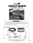
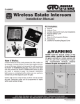
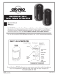
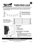
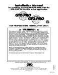
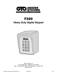
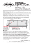
25 Code GTO Digital Keypad
Instructions for Wired and Wireless Installations (FM137-G3 only)
Thank you for purchasing the GTO Digital Keypad. Be sure to read the directions carefully
and completely. Before permanently mounting the keypad, please program the keypad and test
its range.
IMPORTANT: Your keypad may need to be hard wired due to the fact that it must accept
interference according to FCC regulations listed below. For example, applications
that are relativity close to cell towers or airports may receive intermittent interference and
require hard-wiring.
The GTO Digital Keypad is a multipurpose keypad that can work with other applications in
addition to GTO gate openers and locks. As a wireless keypad it can be used with any gate or
garage door opener and must be used in conjunction with the GTO garage door receiver kit
(part # RB709).
SAFETY NOTE: Never install the keypad where a person can reach through the gate to activate
it, or where a person can touch the gate while activating the keypad. The recommended minimum distance between the gate and keypad is 10 ft.
FCC WARNING: Changes or modifications to this unit not expressly approved by the party responsible for compliance could void
the user’s authority to operate the equipment.
NOTE: This equipment has been tested and found to comply with the limits for a Class B digital device, pursuant to Part 15 of the
FCC Rules. These limits are designed to provide reasonable protection against harmful interference in a residential installation.
This equipment generates, uses and can radiate radio frequency energy and, if not installed and used in accordance with the instructions, may cause harmful interference to radio communications.
However, there is no guarantee that interference will not occur in particular installations. If this equipment does cause harmful interference to radio or television reception, which can be determined by turning the equipment off and on, the user is encouraged to
try to correct the interference by one or more of the following measures: • Reorient or replace the receiver antenna. • Increase the
separation between the equipment and the receiver. • Connect the equipment into an outlet on a circuit different from that to which
the receiver is connected. • Consult the dealer or an experienced radio/TV technician for help.
Features of the Keypad
You may program up to 25 different personal entry codes, allowing you to give different entry codes to different users. For example,
you can give a delivery person their own entry code, which you can easily change after they have made the delivery. This will prevent
them from being able to regain access, while still allowing those to whom you gave other entry codes full access.
As a safety feature, after entering a valid code, pressing any key during a 40 second time period from the last key pressed while the
gate is opening will stop the gate. Pressing any key while the gate is stopped will reverse direction of the gate. The keypad will not affect the auto-close setting of your gate opener system.
The keypad face will light up and the beeper will beep at the press of any key. The keypad memory will recognize your entry code in
a string of up to 20 digits. As a security feature, you have a maximum of 20 digits in which to enter the correct code before the keypad
locks you out for 40 seconds. This will discourage an unauthorized person from trying to use random numbers to access your property.
Your entry codes will remain stored in memory even when the batteries go dead. The keypad will remember your entry codes as long
as you don’t press the RESET button.
Limited One Year Warranty
GTO, Inc. gate opener accessories are warranted by the manufacturer against defects in workmanship for a period of one (1) year from the date of purchase, provided recommended installation procedures have been followed.
In the case of product failure due to defective material or manufacturer workmanship within the one (1) year warranty period, the accessory will be repaired or replaced (at the manufacturer’s option) at no charge to the customer, if returned freight prepaid to GTO, Inc., 3121 Hartsfield Rd., Tallahassee,
FL 32303. IMPORTANT: Call 850/575-4144 or fax 850/575-8950 for a Return Goods Authorization (RGA) number before returning goods to factory.
Products received at the factory without an RGA will not be accepted. Replacement or repaired parts are covered by this warranty for the remainder of the
one (1) year warranty period or six (6) months, whichever is greater. GTO, Inc. will pay the shipping charges for return to the owner of items repaired.
The manufacturer will not be responsible for any charges or damages incurred in the removal of the defective parts for repair, or for the reinstallation
of those parts after repair. This warranty shall be considered void if damage to the product(s) was due to improper installation or use, connection to an
improper power source, tampering, or if damage was caused by lightning, wind, fire, flood, insects, or other natural agent.
After the one (1) year warranty period, GTO Inc. or one of its authorized service centers will make any necessary repairs for a nominal fee. Call GTO
at 850/575-4144 for more information. This warranty gives you specific legal rights, and you may also have other rights which may vary from state to
state. This warranty is in lieu of all other warranties, expressed or implied. NOTE: Verification of the warranty period requires copies of receipts or other
proof of purchase. Please retain those records.
rev - 04-07-08 • Printed in China for GTO, Inc.
©2008 GTO, Inc.
Keypad Description
Keypad - Inside
Open Collector Output:
Keypad - Front
PROGRAM Button:
Used to program access codes.
"#$
%&'
()*
+,-
./0
134
567
89:
STATUS Light:
This led will blink once when
any key is pressed and provides
visual feedback during access
code programming.
Used to connect Keypad to gate opener that
accepts logic inputs (All GTO gate openers)
in hard-wired applications. We recommend
using 16 AWG wire.
OUT COM.
RESET
+ – +
RESET Button:
Pressing this button for 2 seconds will
reprogram key pad to factory settings. All
codes are deleted. Default master code is 1234.
– + –
Battery Holder:
Use 3 AA batteries.
Installing Batteries
NOTE: 3 AA batteries are required to power the keypad.
Step 1: Remove the two screws from the bottom of the keypad and separate the keypad from its housing.
Step 2: Install 3 AA batteries (not included).
Wireless Installation of the Keypad
NOTE: For wireless applications, the distance from the keypad to the opener’s receiver
should not exceed 50 ft. Always test the keypad range before permanently mounting it.
Step 1: Mount the keypad cover using the screws provided.
1
4
GHI
Step 2: Slide the keypad into the cover and secure with the small screws provided.
7
PRS
2
ABC
5
JKL
8
TUV
3
DEF
6
MNO
9
WXY
0
NOTE: If you have not changed your opener’s transmitter code from the factory setting,
see the “Setting Your Personal Transmitter Code” section in the gate openers manual then
‘Learn’ the transmitter code into the keypad. See ‘Learn Transmitter Code’ section below.
‘Learn’ Transmitter Code (for wireless installation)
IMPORTANT: Make sure the transmitter operates the gate opener.
• Turn off the gate opener so that there is no unintended operation of the gate during the learning process.
• Press and release the PROGRAM button.
• Enter the Master Code then press and release the PROGRAM button.
• Enter 0,5 then press and release the PROGRAM button.
• Press and hold the transmitter button while holding the transmitter to the bottom of the keypad as shown.
• The keypad will beep 3 times to confirm that the transmitter is successfully ‘Learned.’ Release the
transmitters button at this time.
1
4
GHI
7
PRS
2
ABC
5
JKL
8
TUV
3
DEF
6
MNO
9
WXY
0
1 2 3 4 0 5
Example: Learn transmitter code with Master Code of ‘1234’.
Then press and hold transmitter button until you hear 3 beeps. The round black dot is the ‘PROGRAM’ button.
• Turn the gate opener back on and confirm that the keypad operates the gate using the master code.
Wired Installation of the Keypad
Step 1: Turn the gate opener’s power switch OFF. Use 16 gauge, stranded, direct burial low voltage wire (part no. RB509) to connect the keypad to the opener control board. Run wire through
PVC pipe from the ground to keypad and from the ground to the opener control board to protect
the wire from lawn mowers or grazing animals.
Determine how the wire will enter the keypad (i.e. from the back through a hole drilled in the
mounting post or running the wire on the surface of the post). Remove the small rectangular
knock-out on the back of the keypad cover and pull the wire into the cover. Then mount the cover
to the post using the screws provided.
2
Knock-out
Step 2: To hard-wire the keypad - strip the wires back 3/16” and attach the wires to the terminal block marked OUT COM on the keypad control board as shown to the right making sure
to obey polarity (+ -). Connect the other end to the opener’s control board as shown in Control
Board Connections section below.
NOTE: For a hard-wired application the 318 MHz RF transmitter is automatically disabled.
OUT COM
Step 3: Slide the keypad into the cover and secure with the small
screws provided.
1
4
2
ABC
5
GHI
JKL
7
8
PRS
TUV
#1
Step 4: With the power to the opener turned OFF. Remove opener
control board cover and feed enough of the low voltage keypad wire
through a strain relief to reach the gate opener control board terminals.
3
DEF
6
MNO
Hard-wire from Gate Opener
9
WXY
Step 5: Attach the wires from the keypad to the opener control board terminal
blocks as shown below.
0
#2
Step 6: Replace the control board cover and turn the power switch ON. Test the keypad by entering 1 2 3 4.
Step 7: Program your ‘Personal Master Code’ and any additional entry codes (for a total of 25 entry codes)
you wish. See Programming the Keypad section.
Control Board Connection
NOTE: If your control board doesn’t look like any of these diagrams, please call GTO Technical Service at 1-800-543-1236
or 850-575-4144 for additional support.
Mighty Mule 350 Control Board
LEARN
G
ACCESSORY
Connect #2 wire
from the COM terminal on the
keypad to GRN terminal on
the opener control board.
BLK
Connect #2 wire from the COM
terminal on the keypad to the
COMMMON terminal on the gate
opener control board.
Connect #1 wire from the
OUT terminal on the keypad
to CYCLE terminal on the
gate opener control board.
Connect #1 wire from the
OUT terminal on the keypad
to the WHT terminal on the
opener control board.
RED
RECR
#1
#1
GEN-3 (Blue) Control Boards
Mighty Mule 500 & 502
Control Boards
RECEIVER
OPEN
EDGE
RED
RECEIVER
#2
Connect the #2 wire from the
COM terminal on the keypad
to one of the COM terminals
on the opener control board.
#1
GTO RCVR.
Connect the #1 wire from
the OUT terminal on the keypad to
the CYCLE terminal on the opener
control board.
#1
Connect #2 wire from
the COM terminal on the
keypad to the COM
terminal on the gate
opener control board.
SX4000 L
COM
COM
COM
COM
STOP
CLOSE
OPEN
RUN 2
SHADOW
LOOP
RED
OPEN EDGE
BLK
CYCLE
GRN
SAFETY
OPEN
EDGE
J12
CLOSE
EDGE
SHADOW
LOOP
CYCLE
CLOSE
COM
SAFETY
COM
EXIT
OPEN
J8
J11
COM
COM
GTO/PRO GP-SL100 and GP-SW100
Control Boards
GTO Inc.
#2
GTO/PRO DC Powered PRO-SW3000
and PRO-SW4000 Control Boards
BLK
GRN
CLOSE
EDGE
OPEN
EDGE
SHADOW
EXIT
SAFETY
COM
ALM
Connect #1 wire from the OUT
terminal on the keypad to CYCLE
terminal on the gate opener
control board.
CYCLE
CLOSE
EDGE
SHADOW
LOOP
EXIT/
OPEN
GRN BLK
COM
Connect #2 wire from
the COM terminal on the
keypad to the COM
terminal on the gate
opener control board.
SAFETY
CYCLE
CLOSE
CONTROL INPUTS
COM COM
#2
RED
#2
SAFETY
RCVR
COMMON
ALARM
GRN
LINK
EDGE
B
EXIT
R
CYCLE
WHT
BLU
ORG
GRN
SEQ1
SEQ2
ON
PRO-1000, PRO-SL1000 and Old Mighty Mule
Control Boards
RECEIVER
#2
Connect the #2 wire from the
COM terminal on the keypad
to one of the COM terminals
on the opener control board.
Connect the #1 wire from
the OUT terminal on the
keypad to the CYCLE
terminal on the opener
control board.
Connect #1 wire from the OUT
terminal on the keypad to CYCLE
terminal on the gate opener
control board.
#1
3
#1
#2
Programming the Keypad
Programming Interface:
Delete An Entry Code:
• All codes are four (4) digits in length.
• Entry code is a four (4) digit code needed to activate the gate.
• Master Code is needed to add, remove or reset entry codes.
• Master Code also functions as the entry code under normal operation.
• Factory default Master Code is 1234.
• STATUS light should blink and beeper should beep (once)
whenever any button is pressed.
• If more than 10 seconds elapsed between key presses the unit
returns to normal (idle) operating mode.
• Keypad can only enter program mode from sleep mode
(keypad is turned OFF).
• Keypad will beep three times before going into sleep mode.
• Press and release PROGRAM button.
• Enter the Master Code then press and release PROGRAM
button.
• Enter 0, 3 then press and release PROGRAM button.
• Enter the Entry Code to be deleted then press and release
PROGRAM button.
• Beeper beeps 3 times to confirm that the new Entry Code is
deleted.
NOTE: If no matching code is found or the code is NOT 4-digit
in length then an error condition has occurred, the STATUS
light will flash rapidly and the beeper will sound for 2 seconds
before returning to normal operation, without saving.
Example: Key press sequence to delete entry code ‘3456’ from
memory. (1234 is the Master Code)
Program New Master Code:
• Press and release PROGRAM button.
• Enter the old Master Code then press and release PROGRAM
button.
• Enter 0, 6 then press and release PROGRAM button
• Enter the new Master Code then press and release PROGRAM
button.
• Enter the new Master Code then press and release PROGRAM
button again for confirmation.
• Beeper beeps 3 times to confirm that the new Master Code is
accepted.
1 2 3 4
• Press and release PROGRAM button.
• Enter the Master Code then press and release PROGRAM
button.
• Enter 8, and any number between 1 thru 7 then press and
release the PROGRAM button. The second number indicates
the number of days after which the code will be automatically
removed from memory
NOTE: If memory is full (all 25 locations are already
programmed) or an invalid entry is detected then an error
condition has occurred, the STATUS light will flash rapidly
and the beeper will sound for 2 seconds before returning to
normal operation, without saving.
• Enter the new Entry Code then press and release PROGRAM
button.
• Beeper beeps 3 times to confirm that the new Entry Code is
accepted.
NOTE: If the code is NOT 4-digit in length or an error
condition has occurred, the STATUS light will flash rapidly
and the beeper will sound for 2 seconds before returning to
normal operation, without saving.
Example: Key press sequence to change old Master Code from
1 2 3 4 to 3 1 2 1
0 6
3 1 2 1
3 1 2 1
The round black dot is the ‘PROGRAM’ button.
Program (Add) New Entry Code:
• Press and release PROGRAM button.
• Enter the Master Code then press and release PROGRAM
button.
• Enter 0, 2 then press and release PROGRAM button.
NOTE: If memory is full (all 25 locations are already
programmed) the STATUS light will flash rapidly and the
beeper will sound for 2 seconds before returning to normal
operation, without saving.
• Enter the new Entry Code then press and release PROGRAM
button.
• Beeper beeps 3 times to confirm that the new Entry Code is
accepted.
NOTE: If the code is NOT 4-digits in length or an error
condition has occurred, the STATUS light will flash rapidly
and the beeper will sound for 2 seconds before returning to
normal operation, without saving.
Example: Key press sequence to add “3456” as a new entry
code that will remain valid for 2-days only. (1234 is the
Master Code)
1 2 3 4
0 2
8 2
3 4 5 6
The round black dot is the ‘PROGRAM’ button.
Example: Key press sequence to add “3456” as a new entry
code that will remain valid for 7-days only. (1234 is the
Master Code)
1 2 3 4
Example: Key press sequence to add ‘3456’ as a new entry
code. (1234 is the Master Code)
1 2 3 4
3 4 5 6
Program (Add) New Temporary Entry Code:
NOTE: If the Master Code is not a matched pair or error occurs
(i.e. if the entry code is NOT a 4-digit code) the STATUS light
will flash rapidly and the beeper will sound for 2 seconds before
returning to normal operation with old Master Code.
1 2 3 4
0 3
The round black dot is the ‘PROGRAM’ button.
8 7
3 4 5 6
The round black dot is the ‘PROGRAM’ button.
3 4 5 6
The round black dot is the ‘PROGRAM’ button.
4
Delete ALL Entry Codes:
Normal Keypad Operation:
• Press and release PROGRAM button.
• Enter the Master Code then press and release PROGRAM
button.
• Enter 0, 7 then press and release PROGRAM button.
• Beeper beeps 3 times to confirm that the All Entry Codes are
deleted.
Example: Key press sequence to delete all entry codes from
memory. (for example if 3121 is the Master Code)
• If the user enters a 4-digit code that is matched to one of the
25 stored codes. The STATUS light should blink twice and the
beeper should beep twice to confirm that a matched code is
entered.
• No more than 20 key presses are allowed to obtain the 4-digit
entry code.
3 1 2 1
0 7
The round black dot is the ‘PROGRAM’ button.
Example:
1234 is one of the codes stored in one of the memory location.
The user can enter ‘x1234’ or ‘xxxxxxxxxxxxxxxx1234’ and
the gate should be activated (x is any key). If more than 20 key
presses is entered without matching one of the codes then the
unit’s STATUS light should be flashing rapidly and no entry will
be accepted for the next 40 seconds. The user must not enter
any code for at least 40 seconds before the unit returns to normal operation; otherwise it remains in this ‘lock-down’ mode.
Once the user enters a matched code, any subsequent key press
within the next 40 seconds will re-activate the keypad.
Low Battery Indication Summary:
Low Battery Indicator
Beeps twice when any key is pressed.
Battery OK
Beeps once when any key is pressed.
Keying Indication Summary:
Keying Error Alert Indication
Keying accepted confirmation Indication
Master Code Setting
Speaker: continuous Beep for 2 seconds
STATUS light: rapid flashing Speaker: Beep – Beep – Beep
STATUS light: no light, no flashing
Permanent Entry Code
Speaker: continuous Beep for 2 seconds
STATUS light: rapid flashing
Speaker: Beep – Beep – Beep
STATUS light: no light, no flashing
Temporary Entry Code Setting Speaker: continuous Beep for 2 seconds
STATUS light: rapid flashing
Speaker: Beep – Beep – Beep
STATUS light: no light, no flashing
Entry Code Matching
Speaker: continuous Beep for 2 seconds
STATUS light: rapid flashing
Speaker: Beep – Beep – Beep
(after non-matching 20 keying) STATUS light: no light, no flashing
If you have any questions or concerns, please contact our Technical Service Department at 1-800-543-1236 or 850-575-4144.
GTO, Inc. • 3121 Hartsfield Road • Tallahassee, Florida 32303
Telephone (850) 575-0176 • Fax (850) 575-8912 • website www.gtoinc.com
The contents of all material available on this installation manual are copyrighted by GTO, Inc. (“GTO”), unless otherwise indicated. All rights are reserved by GTO, and content may not be
reproduced, downloaded, disseminated, published, or transferred in any form or by any means, except with the prior, written permission of GTO. Any reprinting of GTO publications is by
permission only. Copyright infringement is a violation of federal law.
GTO®, GTO/PRO®, Mighty Mule® are registered trademarks of GTO, Inc. Professional Access Systems™ is a trademark of GTO, Inc. and are the exclusive property of GTO, Inc. (“GTO”).
All rights are reserved by GTO, and these marks may not be used, in any for without the prior, written permission of GTO.