1
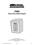
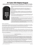
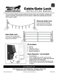
ACCESS
SYSTEMS
PROFESSIONAL RESIDENTIAL
ACCESS
SYSTEMS
PROFESSIONAL RESIDENTIAL
ACCESS CONTROLS
Driveway Alarm
WIRELESS
IN S TAL L AT ION
M A N U A LACCESS
SYSTEMS
Kit Includes:
PROFESSIONAL RESIDENTIAL
A
C
A.Transmitter D.Transformer
B.Sensor
E.Mounting post (3 pcs)
C.Receiver
How It Works:
E
D
The electromagnetic sensor detects vehicles
in motion and sends a signal to the indoor
receiver. The indoor receiver will chime when
it receives the signal.
B
www.mightymule.com • www.gtoaccess.com
Gates that Open, LLC • 3121 Hartsfield Road • Tallahassee, Florida 32303
1-800-543-GATE (4283) • Technical Support 1-800-543-1236
©2012 Gates That Open, LLC
Printed in China for Gates That Open, LLC.
Rev. 03.04.12
Installation Overview
Place the SENSOR immediately next to the driveway to
maximize the sensing range, but at least 25 feet from
roadways, neighbor’s driveways or large moving metal
objects.
The cable connecting the SENSOR and TRANSMITTER
allows for the placement of the TRANSMITTER away from
the driveway in the concealment of landscape or closer
to the RECEIVER.
Up to 400 ft. range
from transmitter to receiver
Senses vehicles and
large moving metal objects
within a 12 ft. radius
The approximate transmitting range from the
TRANSMITTER to the RECEIVER is 400 ft. Range can
vary depending on environmental conditions such as RF
interference and topography. Some adjustment may be
required.
NOTE: DO NOT place the TRANSMITTER in the
direct path of a sprinkler. The TRANSMITTER is
water resistant but not waterproof.
If you don’t use the full length of signal cable from
the SENSOR to the TRANSMITTER, coil the extra
cable and bury it beside the transmitter stake.
Place Driveway Sensor at least
25 ft. from roadways, neighbor’s
driveways to prevent false signals
ROADWAY
For Optimum Performance:
• Locate the SENSOR as far as possible away from power transformers, power lines,
underground gas line, and telephone lines.
• Locate the SENSOR away from general moving traffic to prevent unwanted activation.
Remember that the SENSOR detects MAGNETIC DISTURBANCES caused by a
vehicle’s mass and velocity.
• Range distance is approximate and will vary due to outside interference, type of soil,
vehicle mass, speed, etc.
• It is recommended that you run the Signal Cable inside PVC conduit to prevent
accidental damage.
• Do not run the Signal Cable in conduit with other wires such as AC power or other
control wires.
• The SIGNAL CABLE CANNOT BE SPLICED.
2 Wireless Driveway Alarm Instruction Manual • 03.04.12
Sensor Placement
HOUSE or BUILDING
where RECEIVER is located
Determining Sensor Location
400 ft. Max
Wireless
IMPORTANT: Clear an area 25 ft. in all directions of
metal tools, toys and automobiles, to prevent magnetic
disturbance during testing and installation.
•Determine the optimum location for the SENSOR
using the information found in “Installation
Overview.”
DRIVEWAY
TRANSMITTER
•Dig a hole approximately 1 ft. deep and 1 ft. long
within 2 ft. and parallel to the edge of the driveway.
•Place the SENSOR flat in the hole and parallel to
the driveway.
Signal Cable
25 ft. from
neighbor’s
driveway
SENSOR RANGE:
12 ft. radius (max)
SENSOR:
2 ft. from
driveway (max)
and 1 ft. deep
•Keep the SENSOR and the cable uncovered at
this time.
25 ft. from
roadway
ROADWAY
Transmitter Placement
Determining Transmitter Location
DE
R
IT
SM
AN
TE
CO
IT
NG
TI
SM
AN
TR
TR
TY
VI
TI
NSI
SE
AX
M
IN
M
• Choose a location for the TRANSMITTER module that is far
enough from the driveway edge that vehicles are unlikely to
hit it.
• Run the SENSOR cable through the PVC mounting post and
plug it into the connector at the bottom of the Transmitter
module.
• Leave 2” to 3” of slack in the cable to prevent damage to the
connector when the transmitter is removed.
Connect Sensor Cable
to Transmitter Module
Leave 2” to 3” of slack
in the Sensor Cable
• Test the chosen location before permanently trenching
and setting the TRANSMITTER (see “Placing Receiver and
Testing System” section).
Wireless Driveway Alarm Instruction Manual • 03.04.12
3
Installing Transmitter Batteries
IMPORTANT: “AA” batteries must be installed at the site where the TRANSMITTER will be located to ensure
proper calibration of the transmitter.
TRANSMITTING
1 2 3 4
MAX
TRANSMITTING
TRANSMITTER CODE
1 2 3 4
MAX
SENSITIVITY
MIN
SENSITIVITY
Insert
“AA” Batteries
MIN
TRANSMITTER CODE
• Make sure the SENSOR wire is plugged into the TRANSMITTER.
• Temporarily place TRANSMITTER on the mounting post in ground.
• With TRANSMITTER in desired location install two (2) “AA” batteries.
Placing Receiver and Testing System
Receiver Placement
• Place the indoor RECEIVER in a convenient location.
• Plug the AC transformer into a 110 VAC outlet and the
charger cable into the receiver.
POWER LED
VISITOR LED
LOW BATTERY LED
• The power LED on the front panel will light up, and there
will be a confirmation “beep” tone.
• When a car passes the SENSOR, a signal is transmitted
to the RECEIVER from the TRANSMITTER. After the
RECEIVER receives the signal, it will chime and the visitor
alert LED will turn on and remain lit. The LED can be reset
by pressing the RESET button, but it is not required.
• The LOW BATTERY LED alerts you when the two (2)
“AA” batteries in the outdoor TRANSMITTER need to
be replaced.
RESET BUTTON
VOLUME CONTROL
TRANSFORMER INPUT
Testing the System
• Test the range and system by having someone drive an automobile past the SENSOR to be sure
the RECEIVER is activated when the vehicle has passed the SENSOR. Kitchen appliances or other
electronics may interfere with reception. It may be necessary to adjust the position or relocate the
RECEIVER for optimum results. See Troubleshooting Section on page 6.
4 Wireless Driveway Alarm Instruction Manual • 03.04.12
Permanently Install Sensor and Transmitter
• Once the system is tested and working, remove the
batteries and permanently install the SENSOR, SIGNAL
CABLE and TRANSMITTER.
• Bury the SENSOR approximately 1 ft. deep, flat and
parallel, next to the driveway.
•Dig a narrow trench or slit from the SENSOR to the
TRANSMITTER location using a flat spade or other
tool. The wire from the SENSOR to the TRANSMITTER
should be at least six inches deep to avoid possible
damage.
• Secure the TRANSMITTER on the supplied 3 piece
PVC pipe by burying the bottom third of the pipe in the
soil and tamping the ground around the pipe. DO NOT
cover the TRANSMITTER with a metal cover as this will
cause signal interference.
Leave 2-3 inches of wire
slack inside post so the
transmitter can be remove
without pulling plug loose
when changing batteries.
Transmitter approximately
1 ft. above ground.
Bury any extra wire.
Bury Sensor 1 ft. deep
flat and parallel to driveway.
Edge of Driveway
• Secure the TRANSMITTER mounting post in the
ground so that the TRANSMITTER is upright and
approximately 1 ft. above ground.
• Replace the batteries.
Sensitivity Adjustment
INSIDE TRANSMITTER
TRANSMITTER CODE
1 2 3 4
MAX
MIN
• With the range adjusted to the maximum of 12 ft., a large
metal object moving slowly will be detected up to 12 ft.
from the SENSOR, while a small metal object moving
slowly might not be detected at the same distance.
SENSITIVITY
• The potentiometer varies the sensitivity range of the
SENSOR to avoid unwanted moving metal objects from
activating the alarm, such as: moving gates, metal play
equipment, garage doors, other vehicular traffic, etc.
TRANSMITTING
• The SENSING RANGE can be adjusted from approximately
a 3 to 12 foot radius from the SENSOR.
Sensitivity
Adjustment
Potentiometer
Wireless Driveway Alarm Instruction Manual • 03.04.12
5
Troubleshooting
System not detecting vehicles:
• Remove the outer cover from transmitter and check to see
if LED blinks when a vehicle passes the sensor. The LED
indicates that a vehicle was detected and it is transmitting.
• Is the distance to the base unit within the max range of
400 ft.? Remember that foliage, trees, and buildings in the
line of sight from transmitter to indoor unit will reduce the
transmitting range.
Up to 400 ft. range
from transmitter to receiver
Senses vehicles and
large moving metal objects
within a 12 ft. radius
• Metal buildings such as mobile homes can block the
signal. Try placing the indoor unit close to a window facing
the outdoor sensor.
• Kitchen appliances or other electronics may interfere with
reception. It may be necessary to adjust the position or
relocate the RECEIVER for optimum results.
• Are the DIP switches on the indoor and outdoor units both
set the same?
Place Driveway Sensor at least
25 ft. from roadways, neighbor’s
driveways to prevent false signals
• Make sure receiver volume control is turned up.
• Remove the “AA” batteries - make sure there are no large
metal objects or vehicles within 12 feet of the SENSOR replace the “AA” batteries and allow 60 seconds for it to
recalibrate.
- Replace TRANSMITTER batteries when indoor
RECEIVER’s low battery light comes on.
- In locations where weather varies use Lithium-
Alkaline “AA” batteries for best performance.
ROADWAY
Sensitivity
Adjustment
Potentiometer
Transmitting LED
INSIDE TRANSMITTER
SENSITIVITY
TRANSMITTER CODE
1 2 3 4
MIN
MAX
TRANSMITTING
NOTE: The audible chime will activate once every 15
seconds unless reset button is pressed.
Code Setting
DIP Switches
• Is the sensor installed close to driveway as shown?
TRANSMITTER CODE
• Is the sensor probe at least 25 feet from the edge of
the road? Try moving the sensor farther from the road.
Remember to keep it close to the edge of the driveway.
• Adjust the sensitivity control to reduce sensitivity. Make
small changes until street vehicles are not detected.
Counterclockwise adjustments make the sensor less
sensitive.
Indoor base unit detecting a neighbor’s driveway alert:
• Select a different TRANSMITTER/RECEIVER code using
the 4 position DIP switch on the transmitter and the indoor
unit. Both sets of switches must be set exactly the same.
6 Wireless Driveway Alarm Instruction Manual • 03.04.12
1 2 3 4
Sensor detecting vehicles on the street:
BOTTOM OF RECEIVER
If you change your DIP switch settings make note
here for future reference.
FACTORY CODE
YOUR CODE
1 2 3 4
1 2 3 4
NOTES
Wireless Driveway Alarm Instruction Manual • 03.04.12
7
FCC WARNING: Changes or modifications to this unit not expressly approved by the party responsible for compliance
could void the user’s authority to operate the equipment. In accordance with FCC Part 15, Section 15.21, the manufacturer
is not responsible for any radio or TV interference caused by unauthorized modifications to this equipment. Such
modifications could VOID the user authority to operate the equipment.
NOTE: This equipment has been tested and found to comply with the limits for a Class B digital device, pursuant to
Part 15 of the FCC Rules. These limits are designed to provide reasonable protection against harmful interference in a
residential installation. This equipment generates, uses and can radiate radio frequency energy and, if not installed and
used in accordance with the instructions, may cause harmful interference to radio communications.
However, there is no guarantee that interference will not occur in particular installations. If this equipment does cause
harmful interference to radio or television reception, which can be determined by turning the equipment off and on, the
user is encouraged to try to correct the interference by one or more of the following measures: • Reorient or replace the
receiver antenna. • Increase the separation between the equipment and the receiver. • Connect the equipment into an outlet
on a circuit different from that which the receiver is connected. • Consult the dealer or an experienced radio/TV technician
for help.
GTO Limited One Year Warranty
Gates That Open, LLC gate openers and accessories are covered under warranty by the manufacturer against defects in materials
and manufacturer workmanship for a period of one (1) year from date of purchase, provided the recommended installation
procedures have been followed.
In the case of product failure due to defective material or manufacturer workmanship within the one (1) year warranty period, the
product will be repaired or replaced (at the manufacturer’s option) at no charge to the customer, if returned freight prepaid to GTO,
3121 Hartsfield Road, Tallahassee, Florida, USA 32303. IMPORTANT: Call (800) 543-1236 for a Return Goods Authorization
(RGA) number before returning accessory to factory. Products received at the factory without an RGA number will not be
accepted. Replacement or repaired parts are covered by this warranty for the remainder of the one (1) year warranty period or six
(6) months, whichever is greater. GTO will pay the shipping charges (equal to United Parcel Service GROUND rate) for return to the
owner of items repaired under warranty.
The manufacturer will not be responsible for any charges or damages incurred in the removal of the defective parts for repair, or for
the reinstallation of those parts after repair. This warranty shall be considered void if damage to the product(s) was due to improper
installation or use, connection to an improper power source, or if damage was caused by electrical power surge, lightning, wind, fire,
flood, insects or other natural agent.
After the one (1) year warranty period, GTO, will make any necessary repairs for a nominal fee. Call GTO at (800) 543-1236 for more
information. This warranty gives you specific legal rights, and you may also have other rights which may vary from state to state.
This warranty is in lieu of all other warranties, expressed or implied. NOTE: Verification of the warranty period requires copies of
receipts or other proof of purchase. Please retain these records.
ACCESS
SYSTEMS
ACCESS CONTROLS
PROFESSIONAL RESIDENTIAL
Gates That Open, LLC • 3121 Hartsfield Road • Tallahassee, Florida 32303
www.mightymule.com • www.gtoaccess.com
For online Technical Support visit the Online Troubleshooter Wizard 24 hrs/day 7 days/week at
http://support.gtoinc.com/support/troubleshooter.aspx and open a Tech Ticket
Technical Support Hours: MON - FRI 8:00AM - 7:00PM (ET)
1-800-543-1236