1
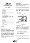
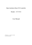
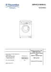
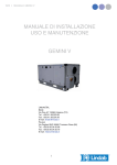
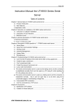
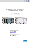
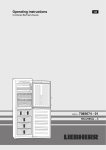
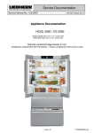
Table of contents CTR07 Introduction .................................................................................................. 3 SIMPLIFIED DISPLAY ............................................................................................. 3 SYNOPTIC DISPLAY .............................................................................................. 4 FANS SPEED ...................................................................................................... 5 BOOSTER FUNCTION ........................................................................................... 7 POST‐HEATING .................................................................................................. 7 SELECTION MENU ............................................................................................. 10 User manual OPERATING STATE............................................................................................. 11 Nr. release: Rev. 04 250711 WEEKLY PROGRAMMING.................................................................................... 13 Software version 3.12 ALARMS .......................................................................................................... 18 USER’S PARAMETERS ......................................................................................... 19 CONFIGURING THE CLOCK ................................................................................... 17 CONFIGURING THE INSTALLATION ........................................................................ 20 INSTALLATION .................................................................................................. 24 TERMS OF GUARANTEE ...................................................................................... 24 UTEK srl. Via provinciale, 30 | 23030 Mazzo di Valtellina (So)
Tel. + 39 0342 862031 | Fax + 30 0342 862029
www.utek.eu | [email protected] 2 Introduction This Control Panel is designed to control machines used to change the air in the simplest way possible. The user activates the air change functions by means of a knob and looking at the graphic display that shows the pertinent windows. Rotating the knob makes it possible to change the values and scroll the menu items, while pressing it confirms the changes or selections made. The icon for closing the window is always displayed at the top right of the screen. To move to the next window, rotate the knob until this icon is reached, and then press the knob. The operating status of the entire air change plant is summarised in the window that is normally displayed, and the user has a choice of a simplified version or a complete overview of the machine. SIMPLIFIED DISPLAY Changing the speed on the fans Rotate the knob clockwise to increase the speed and anticlockwise to reduce it. When timer is selected, the speed is automatically selected according to the weekly programme, whereas when Auto is selected the speed is selected automatically, depending on the quality of the air extractor and the comfort profile configuration. Changing the temperature setting It is available only if the unit is equipped with post‐heating, represent the temperature desired in the room. Rotate the knob clockwise to increase the temperature and anticlockwise to reduce it. Alarms Activated When alarms are activated an icon is displayed along with flashing wording. The wording may indicate dirty filters or suggest calling for assistance with more serious problems. The simplified display provides a basic representation of the machine’s status, indicated by means of large symbols and characters that are even visible from a distance. Only if several machines are installed: the status of the first machine only is displayed but an alarm indication will appear when any of the machines is in alarm. The user can access the simplified window at any time and from any window by simply holding the knob pushed down for 5 seconds. Alternatively, it can be accessed by selecting the Simplified item in the selection menu. Switching to the synoptic window Synoptic display Simplified window To pass to the to the synoptic window, hold the knob down for 5 seconds. The synoptic display provides a detailed graphic representation of the machine’s status and from here all the available functions can be activated. To pass from the simplified window to the synoptic window, hold the knob down for 5 seconds. To access the synoptic window from any other window, close all the windows. Only if several machines are installed: the status of the first machine only is displayed but an alarm indication will appear when any of the machines is in alarm. 3 4 Possible selections are as follows: ‐ off: when this selection is selected, fans are still; however, be aware that the unit is energized anyway; in order to reach this value, turn the knob counterclockwise. Press the knob to confirm your selection. ‐ xxx%: if the unit is fit with stepless adjustment speed fans (CAV or VAV), a percentage value of the fan speed can be set starting from a minimum value (factory setting) up to 100 percent of the available speed; turn the knob clockwise to increase speed and counterclockwise to reduce it. Press the knob to confirm your selection. Speed change steps can be 5 percent or 1 percent (factory setting). If the unit is COP version a value of the desired pressure (to be kept constant) downstream of the fan can be set. The value will be expressed as a percentage of the real full‐
scale. Synoptic window
Controlling fans speed In order to change this parameter, select the field in the top left corner of the synoptic window (turn the knob clockwise or counterclockwise to change the field selection) and confirm your selection by pressing the knob. 1, 2 or 3: If the unit is equipped with 3‐speed fans, any one of the speeds available can be selected: speed 1, speed 2 or speed 3; turn the knob clockwise to increase speed and counterclockwise to reduce it. Press the knob to confirm your selection. 5 6 ‐ When off is set, post‐heating is kept switched off.
•
•
timer: when this option is selected, the fan speed is controlled according to the settings of the weekly timetable (see Program menu). Press the knob to confirm your selection. auto: this mode is only available when a sensor is present (CO2, CO2‐VOC or relative humidity RH) whose measure the fan speed depends on. The auto mode is compatible with the timer mode (see Program menu). Press the knob to confirm your selection. Temperature icon Booster function The booster function can be accessed by selecting the bottom left icon Alarms In case of alarms, a flashing icon and writing are displayed; and the alarm will be also indicated by a flashing red led. The writing may indicate Dirty filters or suggest to Call service in case of more serious problems. By this function, a time interval (from 1 minute to 4 hours) can be selected during which the unit can run at maximum speed. The booster function bypasses any other fan speed control modes. After selecting the function, a digital chronometer (hours.minutes.seconds) is displayed that is preset on 5 minutes; this value can be changed by turning the knob clockwise to increase the booster time or counterclockwise to reduce this time. After selecting the time desired, press the knob to stop the function: the display shows the remaining time to the end of the procedure; when the 00.00.00 value is reached, the speed returns to be controlled in the previously selected mode. If the procedure is to be stopped, just repeat the booster setting operations by selecting 0 minutes. Changing the temperature setting ‐ Rotate the knob until the Temperature icon is selected, which will appear on a dark background. ‐ Press the knob – the temperature set starts to flash. ‐ Rotate the knob to change the temperature setting. ‐ Press the knob to confirm the change made. The set temperature stop flashing. 7 In case of problems when reading a temperature probe, the corresponding value will be not displayed on the screen. The said operation will be inhibited only in case of problems with the exhaust air temperature probe (Tx). 8 System state display Changing window The synoptic window also shows the heat‐recovery VCM unit configuration and operating state. In addition to the features described in above paragraphs, please note: The remaining windows are accessed through the "close window" icon (in the top right corner of the screen): ‐ turn the knob clockwise until you select the icon: the icon will look bright on a dark background; ‐ press the knob to confirm your selection: so, next window will be accessed. • Temperature value read by each probe; •
Unit without by‐pass; SELECTION MENU Various detailed information on the system are accessed by selecting the items in the menu. The menu window is accessed from the synoptic window by following the change window procedure Menu •
Unit with by‐Pass, the bypass state is pointed out by the graphics; The following functions can be accessed from the menu window: •
Unit with hygrostat: the overcoming of the set threshold value is pointed out. •
•
•
•
•
•
•
State; Program; Clock; Alarms; Simplified; Installer; Factory ( protected password, accessible only from factory). 9 10 Selecting an item in the menu ‐
‐
Menu / State turn the knob until you select the desired item, which will be displayed with bright writing on a dark background press the number to confirm your selection: the new window will be displayed. Returning to the synoptic window The synoptic window is accessed from the Menu window by following the change window procedure. OPERATING STATE If the control is used to operate several units (master‐slave mode), a screen will be displayed in the menu with the list of available units (max. 8): Unit1 Unit2 … Unit8 The unit whose state is to be monitored must be selected: turn the knob until the desired unit is highlighted, then press the knob. Te (external): External input air temperature in °C. Tr (return) : Return air temperature in °C.. Tx (expelled) : Exhaust air temperature in °C. Anti‐frost: "Anti‐frost" function state (ON‐OFF). The anti‐frost function is triggered automatically when the temperature taken by the Tx probe drops below 1 °C and then goes off when the temperature returns above 3 °C. The anti‐frost is operated by adjusting the fan speed, the input fan will be inhibited and, at the same time, the return will be forced to its maximum speed. All the above until 3°C are achieved. This in order to avoid the formation of ice in the exchanger. Fan (supply): Input fan speed; this value is expressed as: •
•
If the control is configured for one unit, the state of the unit is shown directly by displaying the values of the parameters that characterize the unit: •
•
rounds per minute (RPM), when fans with tachimetric signal are installed; percentage, when variable speed fans are installed without tachimetric signal (Off when the fan is off); Off, 1 ,2 or 3 for 3‐speed fans. Fan (exhaust.): Exhaust fan speed, see above. Fan hours: Unit operation hours. Bypass: It is on when the ByPass is configured: ByPass open (On) or closed (Off). Heat 1 on‐off: The first post‐heating stage is working or not. Heat 2 on‐off: The second post‐heating stage is working or not. CO2/VOC ppm Amount of air (values less than 700 ppm indicated clean air, while values close to 2000 ppm indicate very dirty air). 11 12 Humidity % : It is on when a humidity probe is present: it indicates the value of relative humidity Default percentage as taken by the probe: it can take values between 0 and 100. When this item is selected , preset values are assigned to parameters: Auto est .% : It is on if the digital input is configurated with an "external signal" 0‐10V : it indicates the value in percentage as taken by the external signal, it can take values between 0 and 100. Time table: Remote: It is on if the digital input is configurated like "remote". When is "on" fan speed is that set in the panel, when is "off" the system force the fans to off. PIR : It is on if the digital input is configurated like "PIR " (Factory). It indicates the state of fans speed when PIR function is active .It can take values max or min. Summer It is on if the digital input is configurated like "summer " (Factory). When the digital input is configurated in this mode the season change‐over will be automatically. It can take values "yes " or "no". Humidity : It is on if the digital input is configurated like "humidity " (Factory) and so a humidistat is Monday through Friday: 1.
2.
3.
4.
5.
6.
7.
8.
00:00 a.m.→ 06:30 a.m. medium speed, post‐heating OFF; 06:30 a.m.→ 08:00 a.m. medium speed, post‐heating ON; 08:00 a.m.→ 11:30 a.m. low‐speed, post‐heating ON; 11:30 a.m.→ 01:00 p.m. high speed, post‐heating ON; 01:00 p.m. → 06:00 p.m. low‐speed, post‐heating ON; 06:00 p.m. → 10:00 p.m. high speed, post‐heating ON; 10:00 p.m. → 00:00 a.m. medium speed, post‐heating OFF; ‐‐:‐‐ → ‐‐:‐‐ speed ‐‐, post‐heating ‐‐. Saturday and Sunday: installed. It indicates whether the humidity threshold has been exceeded (Yes) or not (No). 1.
2.
3.
4.
5.
6.
7.
8.
W.nofrost: It is on when post‐heating is set by water coil and indicates whether the "no‐frost" mode is on digital input is configurated like "w.nofrost" (Factory). When the DI is configured in this mode a thermostat (NC) set to 3°which detect water coil 's temperature must be installed. If the temperature drops below 3° the system will stop the fans and will open the mixing valve. Back to main window The main window is accessed by means of the close icon: ‐ turn the knob to select the icon: this will appear in light letters on a dark background ‐ press the knob to confirm the selection: the menu window will appear WEEKLY PROGRAMMING The Program menu controls the fan speed (on three levels) and the switching on/off of the post‐heating (if available) in a different way each day of the week for different time ranges (from 1 to 8 time ranges to be defined by the user with minimum 30 minute intervals).In order to access the programming functions, turn the knob until the desired item is highlighted and then press the knob. 13 00:00 a.m. → 07:30 a.m. medium speed, post‐heating OFF; 07:30 a.m. → 08:00 a.m. medium speed, post‐heating ON; 08:00a.m. → 11:30 a.m. medium speed, post‐heating ON; 11:30 a.m. → 01:00 p.m. high speed, post‐heating ON; 01:00 p.m. → 06:00 p.m. medium speed, post‐heating ON; 06:00 p.m. → 10:00 p.m. high speed, post‐heating ON; 10:00 p.m. → 00:00 a.m. medium speed, post‐heating OFF; ‐‐:‐‐ → ‐‐:‐‐ speed ‐‐, post‐heating ‐‐. Low speed: off. Medium speed: 030% (in case of adjustable speed fans) – 1 (in case of 3‐speed fans) – auto (in case of CO2 or RH probe). High speed: 065% (in case of adjustable speed fans) – 2 (in case of 3‐speed fans) – auto (in case of CO2 or RH probe). Timetable When the Time Table item is selected, the summary display of each day of the week subdivided into 24 hours is accessed. 14 Just select one day to change its settings. After selecting the day, a list of the eight possible time ranges will be displayed (C1→C8) Time 00.00: the starting time of the current time range is set; this parameter may take a value not smaller than the beginning of the previous time range and not greater than the following time range (with 30‐
minute intervals). Fan speed low: the fan speed may take low, medium and high values. Post‐heating on: if the unit is fit with a post‐heating system, post‐heating can be switched on (on) or not (off). In order to return to the screen with the time ranges, run the change window procedure; now, either set another time range or return to the Time table (change window procedure). Otherwise, set another day or return to the Program menu (change window procedure). The timetable of another day can be set by restarting from the relevant point or copying the timetable of another day: for example, in order to copy the Tuesday timetable to Wednesday, select Wednesday (press the knob) and scroll the time ranges (turn the knob counterclockwise) until the Copy day function is highlighted, then press the knob. Select the day you want to copy from the list of the days of the week (Tuesday) and press the knob. Return to the relevant screen and verify data have been copied properly. Select a specific time range to change its content. The corresponding day is displayed in the top left corner of the screen, while the summary graphic of the timetable is displayed in the bottom part; the other lines of the screen are as follows: Change 1: when this line is selected, the time range that is being modified (1→8) can be changed without having to return to the previous page. 15 Repeat the change window procedure to return to the Program screen (6). 16 Configuring the minutes Setting the speed Low, Medium and High speed preset values can be changed from the Program menu by selecting the corresponding parameter (turn the knob and scroll until the parameter to be changed is highlighted, then press the knob) and selecting the desired value by turning the knob. When the desired value is displayed, press the knob to confirm the choice. The three parameters can take one of the following values: •
•
•
off a percentage value between a minimum and 100% for units with variable speed fans; 1, 2 or 3 for units with 3‐speed fans; auto for units with air quality or relative humidity probe. ‐
‐
‐
‐
turn the knob until the minutes item is selected: it will be bright against a dark background press the knob: the minutes will flash turn the knob to configure the minutes desired press the knob to confirm the configuration: the minutes will be displayed as a bright writing against a dark background. Returning to the menu window The menu window is accessed through the "close" icon: ‐ turn the knob until the icon is selected. The icon will become bright against a dark background ‐ Press the knob to confirm your selection: the menu window will be displayed ALARMS In case of alarms, additional details on the cause of the problem can be obtained by opening the specific window. The alarm window is accessed by selecting the alarm item in the selection menu. Selecting the unit (in case of several machines only) CONFIGURING THE CLOCK The clock window is accessed when the clock item in the selection menu is selected. ‐
‐
Menu / Clock turn the knob until you select the unit whose alarms you want to know: a bright writing against a dark background will be displayed press the knob to confirm your selection: the corresponding alarm windows will be displayed Menu / Alarms Configuring the day ‐
‐
‐
‐
turn the knob until the day item is selected: it will be bright against a dark background press the knob: the currently configured day will flash turn the knob to configure the day desired press the knob to confirm the configuration: the day will be displayed as a bright writing against a dark background. Configuring the hour ‐
‐
‐
‐
17 turn the knob until the hours item is selected: it will be bright against a dark background press the knob: the currently configured hour will flash turn the knob to configure the hour desired press the knob to confirm the configuration: the hour will be displayed as a bright writing against a dark background. Communication: Ok indicates good operation of the communication between the card in the machine and the control panel, while ko indicates communication failure. See installation. Te (external): Ok indicates good operation of the external air temperature sensor, while ko indicates sensor failure. Tr (return): Ok indicates good operation of the return air temperature sensor, while ko indicates sensor failure. Tx(expelled): Ok indicates good operation of the exhaust air temperature sensor, while ko indicates sensor failure. 18 Filters: OK indicates efficient filters. KO indicates dirty filters or ‐ if the alarm is hours based – that the automatic‐on‐off number of hours set in menu installer is elapsed. Fans: OK indicates that the fans are working properly. KO indicates that the fans are faulty. This alarm is available only if the unit is equipped with fans alarm. Go back to the Menu window To access the menu window, use the close icon. ‐ Rotate the knob until the icon is selected, which will appear on a dark background. ‐ Press the knob to confirm the selection made – the menu window opens. USER’S PARAMETERS The user may configure air recycling to achieve the best compromise between maximum yield and satisfying comfort. The parameters window is accessed from the selection menu. The window is only available when the air recycling machine includes a bypass. Additionally, the window will be not displayed if the season is changed automatically (from the factory through an external signal). Two different displays will be available depending on either the bypass control is set according to the season or by on‐off‐automatic control. The adjustment type is set in the factory. Menu / Parameters season based Selecting the season When the right season is selected, the exchanger can be exploited as best as possible through the bypass opening‐closing. However, forgetting to update the season results in wrong operation of the change of air; if the proper update of the parameter cannot be guaranteed, it would be better to select not defined season. The not defined adjustment type is the same as automatic. ‐ turn the knob until the currently set season is selected: it will be displayed as a bright writing against a dark background ‐ press the knob: the currently set season will flash ‐ turn the knob to select the new season ‐ press the knob to confirm your selection: the set season will be displayed as a bright writing against a dark background. On‐Off automatic selection The bypass can be adjusted manually by accessing the parameters window and selecting on or off. Select “automatic” if you want the automatic adjustment instead. Returning to the window menu The menu window is accessed through the "close" icon: ‐ turn the knob until the icon is selected. The icon will become bright against a dark background ‐ press the knob to confirm your selection: the menu window will be displayed CONFIGURING THE INSTALLATION Expert installers can configure the input and exhaust air flows by accessing the installer window from the selection menu. Access is protected by password. The access password is 5678. 19 20 _RH sensor : when a humidity sensor is installed. Also AutoMin% and Automax% parameters can be set: they represent the minimum and maximum air relative humidity values respectively the control will refer to for the automatic fan speed adjustment. _ext signal : when the fans control is via an external 0‐10v signal. Also AutoMin% and Automax% parameters can be set: they represent the minimum and maximum volt values respectively (in percentage) the control will refer to for the automatic fan speed adjustment. Menu / Installer Language This is the possibility to change language ,all settings will be displayed in the language selected default is english. Auto It is the type of sensor installed in the machine: _None : none Filters h 02000 It is activated if the filters alarm is configured as hours in factory . It is the number of cumulated hours after which the system will display an alarm which suggest to clean filters. To reset it the value must be increased to the next number of cumulated hours desired after which the alarm will appear (e.g. 2000 Æ 4000). Max speed It is the maximum fan speed expressed as a percentage of the rated value. Bypass Tmin It is the minimum temperature value the system will refer to for the bypass operation when the adjustment setting is "not defined" or "automatic". Bypass Tmax It is the maximum temperature value the system will refer to for the bypass operation when the adjustment setting is "not defined" or "automatic". _CO2 VOC : when an air quality sensor is installed.Also AutoMin% and AutoMax% parameters can be set: they represent the minimum and maximum air quality values respectively (in ppm, parts per million) the control will refer to for the automatic fan speed adjustment. 21 22 INSTALLATION The machine must be installed by expert staff. Position For the best operation, it must be fixed to an indoor wall, approximately 1.5 m above the floor, far from heat sources (like radiators, stoves, etc.), and must be not exposed to direct sun rays. It must be not fixed to doors, which might slam and damage electronics. Wiring Connect the power to + and – terminals observing the correct polarity. Connect the BUS to the s‐marked 2
terminal. Use of minimum 0.3mm shielded cable is recommended. For communication error check the connections between the control panel and the electronic board. Fan exhau. It is the ratio between the two fan speeds, which has been set by the installer to balance the two air flows (input and exhaust) according to the system needs. The menu window is accessed through the "close window" icon: ‐ turn the knob until the icon is selected. The icon will become bright against a dark background ‐ press the knob to confirm your selection: the menu window will be displayed PIR time m. 010 It is only present when the "PIR" function is on (as set in the factory). It indicates the time (expressed in minutes) during which fans will run at maximum speed after an external consent received from a motion detector. After this span of time, the fans will return to the speed set from the control panel, and then to the minimum speed if no motion is detected in the monitored room. SPECIFICATIONS Power: 9 / 30 VDC 250mW Maximum operating temperature: 0 / 50 °C Maximum storage temperature: ‐20 / 70 °C TERMS OF GUARANTEE Go back to the menu window You can access this window by clicking the close icon: ‐ Turn the knob to select the icon: this appears in light letters on a dark background. ‐ Press the knob to confirm the selection: the menu window displays. 23 The 2 year (24 month) guarantee period starts when the equipment is received. The date of receipt must be proved by the purchasing invoice. During the guarantee period, the manufacturer will repair all faults arising from manufacturing defects or material vices on a free of charge basis. The manufacturer will replace the defective pieces or the entire equipment in its opinion. Any other claims for guarantee performance are excluded. The manufacturer also accepts no responsibility for any subsequent damage. The material that is claimed to be defective must be shipped to the manufacturer through the reseller, together with a detailed description of the fault, to be drawn up by the reseller. The goods will be shipped at the customer's expense. The repaired goods will be shipped at the manufacturer's expense. In no case will the manufacturer be liable for defects caused by improper use that does not comply with the user manual provided and natural events like lightning, floods, earthquakes, fires, etc. The manufacturer accepts no responsibility for repairs or changes to the equipment that have been made by people foreign to the manufacturer. 24