1
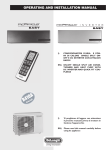
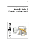
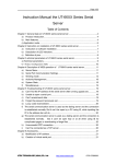
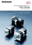
CTR07/EVO PH TOUCH PANEL User manual Release No.: Rev. 00 20/04/13 Software version 4.06.0 UTEK srl. Via provinciale, 30 | 23030 Mazzo di Valtellina (So) Tel. + 39 0342 862031 | Fax + 30 0342 862029 www.utek.eu | [email protected] Content M AIN WINDOW ................................................................................................................................................................................................ 3 Fan Speed Control ..................................................................................................................................................................................... 3 Booster Function ....................................................................................................................................................................................... 4 Air Post‐Treatment Control ....................................................................................................................................................................... 5 Preheating Control (Only EVO‐PH) ............................................................................................................................................................ 6 Menu Selection Window ................................................................................................................................................................................ 6 STATUS M ENU: OPERATING STATUS ................................................................................................................................................................. 7 PROGRAM Menu: Weekly Program Control ................................................................................................................................................... 9 Default ...................................................................................................................................................................................................... 9 Time Table .............................................................................................................................................................................................. 10 Setting Speed Levels ............................................................................................................................................................................... 11 CLOCK Menu: Clock Configuration ............................................................................................................................................................... 12 Setting the Day ........................................................................................................................................................................................ 12 Setting the Hour ...................................................................................................................................................................................... 12 Setting the Minutes................................................................................................................................................................................. 12 ALARMS Menu: Display of the Alarm Status ................................................................................................................................................. 12 Parameters Menu: Setting User Parameters ................................................................................................................................................ 15 INSTALLER Menu: Configuration of System Parameters ............................................................................................................................... 16 Installation .................................................................................................................................................................................................... 21 Wiring ..................................................................................................................................................................................................... 21 Characteristics ......................................................................................................................................................................................... 21 Terms of Guarantee ..................................................................................................................................................................................... 21 2 Main Window The touch‐screen control panel has been designed to control Controlled Mechanical Ventilation units with Heat Return VMC‐ RC in a simple and intuitive way. The user controls the unit by slightly pressing the graphic display icons; the arrow keys that appear after pressing a changeable parameter enable the user to interact with the unit by scrolling menu items and changing values, while any changes or selections must be confirmed by pressing OK. When an icon is pressed, its color turns green and the relevant parameter can be changed. When an item in a submenu is highlighted, it looks white on a blue background: if OK is pressed, the writing turns green and changes can be made using the arrow keys. Main window The main window is a detailed graphic representation of the machine status, from which all available functions can be activated. Press the menu window change icon to change window and access the other menus. From the other windows, select the window change icon and press OK to go back to the previous window. For energy saving purposes, the control enters a stand‐by mode the screen goes off after one minute of inactivity. When any point of the screen is touched, the display restarts automatically. In case of alarms, instead, the display lights up automatically for about half a second every ten seconds. Unit without by‐pass Unit with by‐pass Fan Speed Control In order to change this parameter, press the top left icon in the synoptic display to select it (it will turn green and the arrow keys will appear). Then, press the up arrow key icon to increase or the down arrow key to reduce the percentage value on its side; once the desired value is found, press OK to confirm your selection. Beyond the 100% value, the timer item will appear: if this item is selected, the preset weekly schedule will be started see Program menu . If the unit is also equipped with an air quality or relative humidity probe, or the analog input 0‐10V is enabled that control the fan 3 speed, also the auto option will be available still beyond the 100% value , which enables the fan speed to be automatically adjusted according to the CO2 value, the detected humidity or an external signal. Changing the fan speed In detail, the possible options are as follows: ‐ off: fans are motionless with this option, but watch out that the unit is live anyway; this value is achieved by going below the minimum speed value that can be set; ‐ xxx%: if the unit is equipped with continuously variable speed fans, a fan speed percentage value can be set starting from the minimum value factory setting up to 100% of the available speed with 5% steps 1% on request ; ‐1, 2 or 3: if the unit is equipped with 3‐speed fans, one of the available speeds can be selected: speed 1, speed 2 or speed 3. ‐ clock: with this option, the fan speed is controlled according to the weekly schedule see Program menu . This value is achieved by selecting a greater value than the maximum speed 100% or 3 ; ‐ auto: this option is only available when a sensor CO2, CO2‐VOC or RH relative humidity is available on whose measure depends the fan speed. If an external signal 0‐10V is used to control the fan speed, this value is obtained by selecting a greater value than clock. Booster Function The booster function is accessed when the bottom left icon is selected; a time period from minimum 1 minute to maximum 4 hours can be selected, in which the unit can run at the maximum speed. The booster function has the priority over any other fan speed control method. 4 Booster function After you select the function, a digital chronometer is displayed hours.minutes.seconds , which is preset on a 10 minute value. Such a value can be changed by means of the arrow keys on the right side of the screen: up to increase the booster time and down to reduce that time. After selecting the desired time, press OK to start the functionality: the display shows the remaining time to the end of the procedure. When the 00.00.00 value is reached, the speed returns to be controlled in the previously selected way. When you want to stop the procedure, just repeat the booster setting operations and select a 0‐minute time and press OK. Air PostTreatment Control The control can run an air post‐treatment system with a water‐powered battery modulation of a 3‐point solenoid valve or with a 0‐10V signal, or on‐off control of a 3‐point solenoid valve or an electric resistance controlled through an on‐off control or a PWM‐type modulation . In case of a water‐powered battery, post‐heating and/or post‐cooling control are viable options, while in case of an electric resistance, of course post‐heating only can be controlled. The presence and type of post‐heating to be installed must be selected in the factory. If post‐heating control is set, the main screen is changed: an icon representing a thermometer with a temperature value on its side is displayed in the top right corner, while a box representing post‐heating is displayed on the delivery airflow. Changing temperature set‐point 5 When the bottom right corner icon is selected, the desired interior temperature set‐point TS function is accessed: the user can increase the TS value by the up arrow key or, vice versa, reduce it by the down arrow key. Once the desired value is achieved, the selection is confirmed by pressing OK. TS can take values between 05,0°C and 30,0 °C with 00,1°C steps. If the user selects a TS value lower than 05,0, the control assumes the post‐heating to be off and the off writing is displayed on the screen near the set point temperature icon. The post‐heating status is displayed in the main window: Post‐heating on Post‐heating off Preheating Control (only EVOPH) In addition to post‐heating, the EVO‐PH control can run an electric preheating system controlled by a PWM‐type signal to prevent the formation of ice in the heat exchanger. The control starts the anti‐frost procedure automatically when the temperature detected by the exhaust probe Tx drops below 3°C. The heater is powered at the minimum power, if the Tx temperature keeps dropping, the pre‐ heater power is increased step‐by‐step up to 100% if Tx reaches 1°C. When Tx exceeds 3°C, the procedure stops. The 3°C and 1°C temperature values are set in the factory and can be changed on request. The preheating status is displayed in the main window: Preheating on Preheating off Menu Selection Window The menu window is accessed from the main window by touching the specific icon (window change icon); the white‐text‐on‐blue‐ background top right icon indicates it is selected: then, scroll with the down arrow key and then press OK on the desired item. When the menus are selected (press the down arrow key up to highlight the desired option and press OK to confirm the selection), the various detailed information of the system is accessed. Menu selection window Highlighted menu and window change icon menu window change icon 6 The functions listed here below can be accessed from the menu window: ‐ Status; ‐ Program; ‐ Clock; ‐ Alarms; ‐ Installer; ‐ Factory (password protected, can only be accessed by the factory). The main window is accessed from the Menu window by pressing the up arrow key until the window change icon is highlighted, then pressing OK. STATUS MENU: OPERATING STATUS If the remote control panel is used to run several units (master‐slave mode), a screen will be displayed in the menu with the list of available machines (max 4): Selection of units to be monitored, master/slave configuration Display of the Status menu In order to display the status of one unit, you must select this unit (move by means of the arrow keys and confirm your selection by pressing OK) If the control is configured to run one unit, when this menu is accessed, the status of this unit can be seen right away and the values of the characterizing parameters are displayed; all parameters can be scrolled by using the up and down arrow keys: Te (exter.) Tr (return) Tx (expelled) Ti (input only evo‐ph) Tw (water only evo‐ph) Te (esterna) Tr (ripresa) Tx (espulsa) Ti (ingresso solo evo‐ph) Tw (acqua solo evo‐ph) Wat.anti‐frost (only evo‐ph) Antig. Acqua (solo evo‐ph) Anti‐frost Antig. batt. 7 Temperature of external air in °C Temperature of return air in °C Temperature of expelled air in °C Temperature of input air in °C It is on if water‐powered battery‐operated post‐heating is available: it shows the temperature of the water from the battery, and is expressed in °C It is on if post‐heating is set through water‐powered battery and indicates whether the anti‐frost mode is active. The anti‐ frost function for the battery starts when the temperature detected by the Tw probe (located on the battery) drops below 3°C and then goes off when the temperature returns above 5°C (3+2). When a temperature lower than 3° C is detected, the control valve (hot water) is fully opened in order to prevent ice formation in the elements. Afterwards, if Tw drops below 1°C, also the fans will be stopped and an alarm will be signaled (see ALARM menu). The two temperature levels 3°C and 1°C can be modified (FACTORY menu). Anti‐frost function status (ON‐OFF). The anti‐frost function starts automatically when the temperature detected by the Tx probe drops below 1°C and then goes off when the temperature rises above 3°C. The purpose is to avoid ice formation in the heat exchanger. When it is on, there are two different control methods according to the factory settings: ‐ when the anti‐frost is controlled by a preheating resistance, the latter is triggered until 3°C is reached. ‐ when the anti‐frost is controlled through the adjustment of the fan speed, the input fan will be blocked and the return fan will be powered to the maximum speed at the same time. Fan (supply) Vent.( ingr.) Fan (exhau.) Fan hours By‐pass Vent.( estr.) ore Vent. By‐pass Heat riscald. CO2 /VOC ppm CO2 /VOC ppm Humidity % Umidità % Auto ext .% Auto est .% Remote Remote Boost (only evo‐ph) Boost (solo evo‐ph) PIR PIR Summer estate Humidity Umidità Fire fuoco All the above until 3°C is reached. Supply fan speed value, which is expressed in: ‐ revolutions per minute (RPMs) if fans with tachometric signal are installed; ‐ percentage if variable speed fans without tachometric signal are installed (Off when the fan is off); ‐ Off, 1 ,2 or 3 for 3‐speed fans. Expulsion fan speed, see above. Unit operation hours. It is on if the by‐pass is configured: ‐ On By‐pass open; ‐ Off By‐pass closed. It is on if the water or electric air after‐treatment is configured: ‐ On post‐treatment on; ‐ Off post‐treatment off. It is on if a CO2 or CO2/VOC probe is present: it indicates the CO2 or CO2/VOC concentration in parts per million (ppm) detected by the air quality probe: it can take values between 0 and 2000. It is on if a relative humidity probe is present: it indicates the percentage relative humidity value detected by the probe. It can take values between 0 and 100. It is on if the automatic operation of fans is configured through a 0‐10V external signal. It indicates the percentage value of the external signal (10V corresponds to 100%). It is on if the digital input (DI) is configured as remote (this parameter can be set in the factory): ‐ On if the DI is open (the fans run at the speed set on the remote panel); ‐ Off if the DI is closed (fans are still). It is on if the digital input (DI) is configured as booster (this parameter can be set in the factory): ‐ end the DI is open and a longer time than Boost min. has lapsed after the last change of DI status (from closed to open), booster off (fans at the speed set by the control); ‐ Max the DI is closed or the Boost min. time (1→ 240 minutes) has not lapsed yet since the DI has passed from closed to open, booster on (fans at the maximum speed). It is on if the digital input (DI) is configured as PIR (this parameter can be set in the factory): ‐ min the DI is open (fans at minimum speed); ‐ max the DI is closed (fans at the maximum speed) and the PIR min. time (1→ 240 minutes) fixed in the installer menu has not lapsed yet ; ‐ off the DI is closed (fans at the speed set by the user on the control) and the PIR min. has lapsed after the DI input has closed. It is on if the remote digital input is configured as summer (from the factory). ‐ Yes the DI is open, the summer season is set; ‐ No the DI is closed, the winter season is set. It is on if the remote digital input is configured as humidity (from the factory). ‐ Yes the DI is closed, the humidity threshold of the hygrostat has been overcome; ‐ No the DI is open, the hygrostat humidity threshold has been not overcome. It is on if the remote digital input is configured as fire (from the factory). ‐ Yes the DI is open (exhaust fan at the maximum speed and delivery fan off). ‐ No the DI is closed (fans at the speed set by the control). 8 PROGRAM Menu: Weekly Program Control This menu controls the fan speed (on three levels) and the air after‐treatment on/off options (if available) in a different way for each day of the week, by time period (1 to 8 time periods that can be defined by the user in 30‐minute steps). To access the program control functions, select the Program item by the arrow keys, highlight it and press OK. Program menu Default When this menu item is selected and OK is pressed, unit control parameters are automatically assigned default values: Time table Program valid Monday through Friday Time period C1 00:00 → 06:29 C2 06:30 → 07:59 C3 08:00 → 11:29 C4 11:30 → 12:59 C5 13:00 → 17:59 C6 18:00 → 21:59 C7 22:00 → 00:00 C8 Not used Program valid Saturday and Sunday Time period C1 C2 C3 C4 C5 C6 C7 C8 00:00 → 07:29 07:30 → 07:59 08:00 → 11:29 11:30 → 12:59 13:00 → 17:59 18:00 → 21:59 22:00 → 00:00 Not used Low speed: Medium speed: High speed: 9 Air after‐treatment status: (ON / OFF) Fan speed Medium Medium Low High Low High Medium ‐ OFF ON ON ON ON ON OFF ‐ Air after‐treatment status: (ON / OFF) Fan speed Medium Medium Medium High Medium High Medium ‐ OFF ON ON ON ON ON OFF ‐ Speed levels OFF 030% if the unit is equipped with variable speed fans; 1 if the unit is equipped with 3‐speed fans; auto if the unit is equipped with a CO2 or relative humidity probe, or is controlled through a 0‐10V external signal. 065% if the unit is equipped with variable speed fans; 2 if the unit is equipped with 3‐speed fans; auto if the unit is equipped with a CO2 or relative humidity probe, or is controlled through a 0‐10V external signal. Time Table When this menu item is selected and OK is pressed, the summary display of each day of the week subdivided into 24 hours is accessed. Time table: summary display Time table: detail of one day of the week In order to change the settings of each day, just select the day in the summary display window and press OK; now, the detail screen of the selected day is displayed with the list of the eight possible time periods (C1→C8), while the selected day of the week is displayed in the top left corner of the screen. Selecting the time period to be changed Changeable parameters in the selected time period You can change the content of a time period by selecting the period and pressing OK in the time period change screen; the graphic summary of the program for the entire day is displayed in addition to the selected day (top left corner). The parameters that can be changed are as follows: ‐ ‐ ‐ ‐ Change X: change the time period you are working on without returning to the previous page by selecting this line and pressing OK: scroll the several time periods (1→8) using the arrow keys and just press OK when you reach the desired period. Time hh.mm: set the starting time of the current time period by selecting this line and pressing OK: the arrows keys increase (up arrow) or decrease (down arrow) the time by 30‐minute steps; press OK when you find the desired value; the value of this parameter can be comprised between the beginning of the previous time period and the beginning of the next time period. Fan speed xxx: set the fan speeds required for the current time period by selecting this line and pressing OK: scroll the three possible values (low, medium and high) using the arrows keys; press OK when you find the desired value. These values match the settings according to next paragraph (Speed level setting). Post‐heating on/off: this parameter is only visible if the control is configured to run an air after‐treatment device; enable (on) or disable (off) the air after‐treatment device by selecting this line and pressing OK. Scroll the two possible values (on and off) using the arrow keys: press OK when you find the desired value. After customizing one day of the week according to your need (for instance, Monday), you can copy your program to another day without repeating the procedure described above. In the time period summary window, select the day you want to copy the previous program to (for instance, Tuesday), and press OK. Now, the detail window of the time periods of the selected day Is displayed. Scroll all of the time periods using the down arrow key and reach the Copy day line (it will be after the C8 time period): highlight this line and press OK. 10 Selecting the copy day function Copy day: selecting the day to be copied After accessing the Copy day page (as displayed in the top left corner of the screen), you can select the day you want to copy the program from using the arrow keys to scroll the various days. After identifying the selected day (Monday in our example), press OK to confirm the copy and you are automatically taken to the simplified display page of the time periods (in our case, the Monday program will have been copied to Tuesday). This operation can be repeated for other days of the week. Setting Speed Levels To change the preset values for the three speed levels (low, medium and high) used for the weekly program, reach the main page of the Program menu, highlight the speed level to be changed (for example, Low‐speed) using the arrow keys and press OK. Scroll the possible values by using the arrow keys and, after finding the desired value, confirm your choice by pressing OK. Possible values for these three parameters are as follows: ‐ ‐ ‐ ‐ off: fans off. It can be set by pressing the down arrow key for a few seconds (off is below the minimum speed value that can be set); xxx%: for units equipped with variable speed fans, you can select a percentage value between the minimum (factory setting) and 100%; 1, 2 or 3: for units equipped with 3‐speed fans, you can choose among speed 1, 2 or 3; auto: for units equipped with an air quality or relative humidity probe or controlled through a 0‐10V external signal, the fan speed will be automatically controlled by one of these devices. It can be reached by pressing the up arrow for a few seconds (auto is above the maximum speed value that can be set). 11 CLOCK Menu: Clock Configuration You can set the day of the week and the current time for the proper control of the weekly time program through this menu. Clock menu Setting the Day Select the day line and press OK: the color of the writing of the current day configured will turn green. Scroll by means of the arrow keys to find the desired day. Press OK to confirm your choice: the color of the day will turn from green to blue. Setting the Hour Select the hours line and press OK: the color of the writing of the current hour configured will turn green. Scroll by means of the arrow keys to find the desired day. Press OK to confirm your choice: the color of the day will turn from green to blue. Setting the Minutes Select the minutes line and press OK: the color of the writing of the minutes will turn green. Scroll by means of the arrow keys to find the desired day. Press OK to confirm your choice: the color of the day will turn from green to blue. ALARMS Menu: Display of the Alarm Status If the control detects an abnormal status, the latter is indicated in the main control screen by a specific flashing icon and a red writing at the top of the screen (Call service or Dirty Filters). If the alarm is detected when the screen is in stand‐by mode, the display flashes at about 10‐ second intervals. Signaling an alarm: external air temperature program Alarms menu 12 If an alarm is being signaled, you can reach the specific menu directly by touching the screen. Otherwise you must select the Alarms item in the menu selection page and press OK. If the control is interlocked to several units (master/slave mode), you must select the unit you want to monitor (see Status menu), otherwise you direct access to the detail alarms page. List of ALARMS Parameter 13 Val Communication Comunicazione Te (external) Te (esterna) Tr (return) Tr (ripresa) Tx (expelled) Tx (espulsa) Ti (input only evo‐ph) Ti (ingresso solo evo‐ph) Tw (water only evo‐ph) Tw (acqua solo evo‐ph) Tw(water) low (only evo‐ph) Tw(acqua) bassa (only evo‐ ph) Filters Filtri Status The communication between the machine cards ok and the remote control panel works properly Problem with the communication among cards and remote panel: 1) check electrical connections between electric panel and remote panel (see wiring diagram); 2) if the problem is not solved, check ko electrical connections between the cards (see wiring diagram); 3) if the problem is not solved, check the dipswitch position in both cards (see …); 4) if the problem is not solved, replace the electronic cards. ok The external air temperature sensor works properly Problem with the external air temperature sensor: 1) check electrical connections of the temperature probe (see wiring diagram); ko 2) if the problem is not solved, replace the temperature probe 3) if the problem is not solved, replace the electronic card. ok The return air temperature sensor works properly Problem with the return air temperature sensor: 1) check electrical connections of the temperature probe (see wiring diagram); ko 2) if the problem is not solved, replace the temperature probe 3) if the problem is not solved, replace the electronic card. ok The exhaust air temperature sensor works properly Problem with the expelled air temperature sensor: 1) check electrical connections of the temperature probe (see wiring diagram); ko 2) if the problem is not solved, replace the temperature probe 3) if the problem is not solved, replace the electronic card. ok The input air temperature sensor works properly Problem with the input air temperature sensor: 1) check electrical connections of the temperature probe (see wiring diagram); ko 2) if the problem is not solved, replace the temperature probe 3) if the problem is not solved, replace the electronic card. It is present only if the air after‐treatment control is equipped with a water‐powered battery (Factory menu) The water‐powered battery temperature sensor ok works properly Problem with the water‐powered battery temperature sensor: 1) check electrical connections of the temperature probe (see wiring diagram); ko 2) if the problem is not solved, replace the temperature probe 3) if the problem is not solved, replace the electronic card. It is present only if the air after‐treatment control is equipped with a water‐powered battery (Factory menu) The temperature of the water from the battery is ok higher than a safety threshold, there is no risk of water freezing in the battery ko Risk of liquid freezing in the water‐powered battery It is present only if the filter status alarm with differential Fans Ventilatori CO2 VOC RH sensor UR sensor Ext.signal Segnale est. AutoMinutes AutoMinuti manostat is configured or is based on the machine operation hours (Factory menu) ok Clean filters Clogged filters: replace filters. If the filters alarm is ko based on the machine operation hours, you must reset the Filter Hours parameter (Installer menu) It is present only if the fan status alarm is configured with differential manostats, with tachometric signal of fans or with fan Digital Output (Factory menu) ok ko It is present only if the fan speed automatic control is configured with a CO2 o CO2‐VOC sensor (Installer menu) ok ko It is present only if the fan speed automatic control is configured with a relative humidity sensor (Installer menu) ok ko It is present only if the fan speed control is configured with an external 0‐10V analog signal (Installer menu) ok The external signal source works properly External signal not present (voltage at the clamps = 0V): 1) check electrical connections of the external source (see electric diagram); ko 2) if the problem is not solved, check whether the external signal is present (tester) and its value is greater than 0V; 3) if the problem is not solved, replace the electronic card.. It is present only if the fan speed automatic control alarm is configured with a CO2 o CO2‐VOC sensor, a relative humidity sensor, or with an external signal, and if the AutoMinutes parameter is set on a different value from no (Installer menu). ok Auto probe works properly Possible anomaly in the operation of the auto ko probe 14 Parameters Menu: Setting User Parameters The parameters menu is only displayed when the control is configured to run the by‐pass and/or a water‐powered battery in heating/cooling mode. Change the values of the available parameters by selecting the desired parameter (scroll by the arrow keys to highlight parameters) and pressing OK; now, the color of the current value of the parameter turns green. Use the arrow keys to scroll the several possible values. Press OK when you find the desired value. By‐pass configured in universal mode (Factory menu): three values can be selected for the by‐pass parameter: By‐pass automat. A temperature range is identified between TMIN and TMAX, which is considered comfortable for the user; if the internal temperature (Tr) is in this range, the by‐pass will remain closed. When Tr is out of this range (Tr>TMAX or Tr<TMIN), the control will open the by‐pass if the external temperature (Te) is comprised in the comfort range (TMIN≤Te≤TMAX). Otherwise, the by‐pass will remain closed. Universal by‐pass operation in automatic mode By‐pass off The by‐pass will remain closed irrespective of the internal and external temperature. By‐pass on The by‐pass will remain open irrespective of the internal and external temperature. By‐pass configured in a "seasonal" mode and/or control of a water‐powered battery enabled for air post‐cooling (Factory menu). This parameter is unavailable when the digital input is configured for the automatic season change (Factory menu): Winter season The by‐pass opens if the external temperature is higher than the internal temperature (free heating); the water‐powered battery is run in heating mode Summer season The by‐pass opens if the external temperature is lower than the internal temperature (free cooling); the water‐powered battery is run in cooling mode Not defined season This value is only available when the water‐powered battery is not provided for post‐cooling; the by‐pass is run in a similar way as the automatic mode in the point above. 15 INSTALLER Menu: Configuration of System Parameters You must enter a password (5678) to access this menu: this is a measure to prevent inexperienced users from unintentionally changing parameters, an event that may jeopardize the proper operation of the system. Entering the password Installer menu In order to enter the password, press the up arrow key: the line where the password must be entered is highlighted. Press OK and the color of the first digit turns green: select the desired value for the first digit using the up/down arrow keys and press OK when you reach the desired value. Repeat this operation for the three remaining figures. If you have entered the correct password, the installer menu is displayed; otherwise, if the password is wrong, you are redirected to the password entry page. To change the parameters of this menu, highlight the desired parameter by scrolling up/down the arrow keys and press OK. The color of the currently set value for this parameter is green: now, you can change this value using the up/down arrow keys. When you reach the desired value, press OK to confirm your selection. PARAMETERS AVAILABLE IN THE INSTALLER MENU Language Auto With this parameter, you can select the language of all menus (except for the Factory menu, which will always be in English). GB English language (default) FR French language ES Spanish language IT Italian language NL Dutch language With this parameter, you can configure a device that automatically adjusts the fan speed. See the wiring diagram for the connection of the device External signal The fan speed will be controlled through an external 0‐10V analog signal (default value); if the external signal takes the 0V value, the control will indicate a problem with the source of the external signal. For a unit equipped with adjustable speed fans. FAN speed MAX MIN AutoMin% INPUT signal AutoMax% Where AutoMin% corresponds to the input signal percentage value for which fans must run at the minimum speed, AutoMax% corresponds to the input signal percentage value for which fans must run at the maximum speed. For a unit equipped with 3‐speed fans. 16 FAN speed SP.3 SP.2 SP.1 ‐Δ +Δ SP.1,2% ‐Δ +Δ INPUT signal SP.2,3% SP.1,2% SP.2,3% and Δ values depend on the values of parameters AutoMin% and AutoMax% according to the following formulas: % . 1,2% . 2,3% 7 10 ∆ UR sensor CO2 VOC % % 5 % % % 12 % % The fan speed will be controlled by a relative humidity (RH) sensor with 0‐10V output and will have a linear trend between 0 and 100% RH (0V corresponds to 0% RH and 10V corresponds to 100% RH); if the external signal of the RH sensor takes the 0V value, the control will display a problem with the sensor. See graphs of the segnale es parameter. In this case, AutoMin% corresponds to the relative humidity value for which the air quality is held to be excellent, AutoMax% corresponds to the relative humidity value for which the air quality is held to be very bad. The fan speed will be controlled by a CO2 (or CO2‐VOC) sensor with a 0‐10V output and will have a linear trend between 0 and 2000 ppm (0V corresponds to 0% ppm and 10V corresponds to 2000 ppm); if the external signal of the CO2 sensor takes the 0V value, the control will display a problem with the sensor. For a unit equipped with adjustable speed fans. FAN speed MAX MIN AutoMinppm INPUT signal AutoMaxppm Where AutoMin ppm corresponds to the CO2 (CO2‐VOC) concentration for which the air quality is held to be excellent, AutoMax ppm corresponds to the CO2 (CO2‐VOC) concentration for which the air quality is held to be very bad. For a unit equipped with 3‐speed fans. 17 FAN speed SP.3 SP.2 SP.1 ‐Δ +Δ SP.1,2% ‐Δ +Δ INPUT signal SP.2,3% SP.1,2% SP.2,3% and Δ values depend on the values of both parameters AutoMin ppm and AutoMax ppm according to the following formulas: . 1,2% . 2,3% 7 10 7 . 1,2% 2 5 . 2,3% This parameter is only available if the auto parameter is set on ext. signal or UR sensor. It can take values between 0 and 99% (1% steps) with the following limit: AutoMin%<AutoMax% For a unit equipped with variable speed fans: If auto ext. signal corresponds to the input signal percentage value for which fans turn at the maximum speed; above this value, fans remain set at the maximum speed. For instance, the value AutoMin% 080 corresponds to an 8V (80% of 10V) input signal. If auto UR sensor corresponds to the (percentage) relative humidity for which fans turn at the maximum speed; below this value, fans remain set at the maximum speed. For a unit equipped with 3‐speed fans, referring to the second image of the auto ext. signal parameter, after fixing the SP.1,2% and SP.2,3% values (the nominal values at which speed changes from 1 to 2 and from 2 to 3), the correct value to be assigned to the parameter can be obtained as follows: % AutoMin ppm 12 none (default value) no device is installed for the automatic operation of the fan speed. This parameter is only available if the auto parameter is set on ext. signal or UR sensor. It can take values between 0 and 99% (1% steps) with the following limit: AutoMin%<AutoMax% For a unit equipped with variable speed fans: If auto ext. signal corresponds to the input signal percentage value for which fans turn at the minimum speed; below this value, fans remain set at the minimum speed. For instance, the value AutoMin% 030 corresponds to a 3V (30% of 10V) input signal. If auto UR sensor corresponds to the (percentage) relative humidity for which fans turn at the minimum speed; below this value, fans remain set at the minimum speed. For a unit equipped with 3‐speed fans, referring to the second image of the auto ext. signal parameter, after fixing the SP.1,2% and SP.2,3% values (the nominal values at which speed changes from 1 to 2 and from 2 to 3), the appropriate value to be assigned to the parameter can be obtained as follows: % AutoMax% ∆ AutoMin % 5 8 . 2,3% 3 5 . 1,2% This parameter is only available if the auto parameter is set on CO2 VOC. It can take values between 0 ppm and 1980 ppm (20ppm steps) with the following limit: AutoMin ppm<AutoMax ppm For a unit equipped with variable speed fans, it corresponds to the CO2 (CO2‐VOC) concentration, expressed in ppm, for which fans turn at the minimum speed; below this value, fans remain set at the minimum speed. For a unit equipped with 3‐speed fans, referring to the second image of the auto CO2 VOC parameter, after fixing the SP.1,2% and SP.2,3% values (the nominal values at which speed changes from 1 to 2 and from 2 to 3), the correct value to be assigned to the parameter can be obtained as follows: 18 7 AutoMaxppm AutoMinutes AutoOn % (only evo‐ph) AutoOff% (only evo‐ph) AutoOn ppm (only evo‐ph) AutoOff ppm (only evo‐ph) By‐pass Tmin By‐pass Tmax Filter hours Max speed . 1,2% 2 . 2,3% 5 This parameter is only available if the auto parameter is set on CO2 VOC. It can take values between 20 ppm and 2000 ppm (20ppm steps) with the following limit: AutoMin ppm<AutoMax ppm For a unit equipped with variable speed fans, it corresponds to the CO2 (CO2‐VOC) concentration, expressed in ppm, for which fans turn at the maximum speed; below this value, fans remain set at the maximum speed. For a unit equipped with 3‐speed fans, referring to the second image of the auto CO2 VOC parameter, after fixing the SP.1,2% and SP.2,3% values (the nominal values at which speed changes from 1 to 2 and from 2 to 3), the correct value to be assigned to the parameter can be obtained as follows: 8 . 2,3% 3 . 1,2% 5 This parameter is only available if the auto is set at a value different from none. No (default value) it does not affect the system operation. Its value is expressed in minutes and represents the interval lapsed from the time when the 000→240 signal of the extern device for the auto mode has achieved or exceeded the AutoMax%, or Auto Max ppm value, without dropping below this value, beyond which an anomaly to the external device (CO2, HR probe or external signal) is notified. This parameter is only available if the auto parameter is set on ext. signal or UR sensor and the digital output is configured as auto cmp. Default value 050, is expressed in %; for values of HR% as read by the relative humidity sensor 000→100 (or for values of the 0‐10V external signal expressed as a percentage) lower than the set value, the digital output changes its status. This parameter is only available if the auto parameter is set on ext. signal or UR sensor and the digital output is configured as auto cmp. Default value 050, it is expressed in %; for values of HR% as read by the relative humidity 000→100 sensor (or for values of the 0‐10V external signal expressed as a percentage) higher than the set value, the digital output returns to its standard status. This parameter is only available if the auto parameter is set on CO2 VOC and the digital output is configured as auto cmp. Default value 0500, it is expressed in ppm; for ppm values as read by the CO2 probe lower than 0000→2000 the set value, the digital output changes its status. This parameter is only available if the auto parameter is set on CO2 VOC and the digital output is configured as auto cmp. Default value 0500, it is expressed in ppm; for higher values of ppm as read by the CO2 probe 0000→2000 than the set one, the digital output returns to its standard status. This parameter is on if the control is configured for the control of the by‐pass (Factory menu) Default value 15, it is expressed in degrees centigrade. It is the minimum temperature value (T 12→18 min) the system will refer to for the control of the by‐pass if By‐pass automat. or Stagione non def. are set in the Parameters menu (see Parameters menu). This parameter is on if the control is configured for the running of the by‐pass (Factory menu) Default value 22, it is expressed in degrees centigrade. It is the maximum temperature value (T 20→30 max) the system will refer to for the control of the by‐pass if By‐pass automat. or Stagione non def. are set in the Parameters menu (see Parameters menu). This parameter is on when the clogged filters alarm is based on the hours of operation of the unit (Factory menu) Default value 02000, it is expressed in hours. It represents the number of operation hours of 00000→99999 the unit after which the clogged filters alarm is triggered. In order to reset the alarm, the installer will have to set the new limit at which the alarm must be signaled (check the current operation hours in the parameters status menu Fan hours): This parameter is available if the control is set to run variable speed fans (Factory menu) 055%→100% Default value 100%, it is the maximum fan speed expressed as a percentage of the nominal value (reduction of the maximum speed). The maximum speed that can be set in the main window will always be 100% also for Vel.max values lower than 100%; what changes is the minimum speed value that can be set by the final user: 100 Exh. Fan = XXX% Input Fan 19 100 100 100 100 VE= percentage of exhaust fan speed vs input fan (see next paragraph) INTECCESSO = rounds up to the next integer VMIN = minimum speed set in the Factory menu step = discrete values of the speed values that can be set (5%, it can be set at 1% on specific request, Factory menu) This parameter is available if the control is set to run variable speed fans (Factory menu) 074%→135% Default value 100%, it expresses, in a percentage format, the desired ratio between the exhaust fan speed and the input fan speed that generates an imbalance between the air flows. The maximum speed that can be set in the main window will always be 100%, what changes is the minimum speed value that can be set by the final user (see Max. speed). Ti (in)min (only evo‐ph) Ti min inv. (only evo‐ph) Ti min est. (only evo‐ph) Ti (in)max (only evo‐ph) Valv.sec. (only evo‐ph) Pir min. Boost min. (only evo‐ph) This parameter is available if the control is set to run an electric or modulated water‐based after heating system (no water‐based cooling) 16→20 Default value 18, it is expressed in degrees centigrade; it is the minimum value of the range in which the control keeps the temperature of the delivery air flow: This parameter is available if the control is set to run a modulated water‐based air after‐treatment system. 16→20 Default value 18, it is expressed in degrees centigrade; it is the minimum value of the range in which the control keeps the temperature of the delivery air flow in heating mode (Parameters menu, Winter season): . This parameter is available if the control is set to run a modulated water‐based air after‐treatment system (heating/cooling). Default value 22, it is expressed in degrees centigrade; it is the minimum value of the range in 20→24 which the control keeps the temperature of the delivery air flow in cooling mode (Parameters menu, Summer season): . This parameter is available if the control is set to run an electric after‐heating system or a modulated water‐based heating/cooling system. Default value 30, it is expressed in degrees centigrade; it is the maximum value of the range in 28→32 which the control keeps the temperature of the delivery air flow in heating or cooling mode (see parameters Ti (in)min, Ti min inv. and Ti min est.). This parameter is available if the control is set to run a modulated water‐based post heating/cooling system. 60→600 Default value 120, it is expressed in seconds; it indicates the opening/closing time of the solenoid valve, it is adjustable in 10‐second steps. This parameter is available if the digital input is configured at the PIR value (Factory menu) Default value 10, it is expressed in minutes; it is the time during which the fans run at the 001→240 maximum speed after the pulse (closing of a NO contact) from a presence detector. After this lapse, the fans will return to run at the speed set from the control panel until the pulse from the presence detector is lost; since now on, the fans will run at the minimum speed. This parameter is available if the digital input is configured at the booster value (Factory menu) Default value 10, is expressed in minutes; after the pulse from an external contact (closing of a 001→240 NO contact) the fans run at the maximum speed (booster). When the pulse from the external contact is lost (external contact open), the fans keep running at the maximum speed for the time fixed by this parameter. When the booster function is off, the fans run at the speed set on the control panel. CLOSED DI OPEN MAX FAN speed SET Booster time TIME 20 Installation Installation must be carried out by expert staff. For the best operation, the remote panel must be fixed to an indoor wall about 1.5 m above the floor, far from heating sources (radiators, stoves, etc.), and must be not exposed to direct sun rays. It must be not installed near doors, which might damage the electronics if slammed. Wiring Connect the power supply to the 24V and G terminals, matching the correct polarity. Connect the BUS to the S terminal. Using a min. 0.3 mm2 section shielded cable is recommended. In case of communication errors, check the connections between the remote panel and the electronic card. Remote panel: rear view Characteristics Power: 9 / 30 VDC 250mW, operating temperature between 0° and 50 °C; storage temperature between ‐20 °C and 70 °C. Terms of Guarantee The two‐year (24‐month) guarantee period starts from the receipt of the equipment: the date of receipt must be indicated in the purchase invoice. In the guarantee term, the manufacturer will repair all defects arising from manufacturing mistakes or material faults free of charge. It will replace defective parts or the whole equipment at its own discretion. Any other request for guarantee service is excluded. The manufacturer also waives any liability for subsequent damages. Goods that are claimed to be defective must be shipped to the manufacturer through the dealer, together with a detailed description of the fault written by the dealer. Shipment cost will be charged to the customer. The manufacturer shall bear the cost of returning the repaired goods. In no case will the manufacturer be responsible for defects caused by improper use that does not comply with the user manual provided, and natural catastrophic events like lightning, floods, earthquakes, fire, etc. The manufacturer also waives any liabilities for repairs or changes to the equipment made by any people foreign to the manufacturing company. 21