1
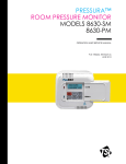
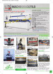
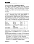
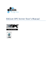
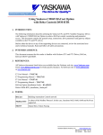
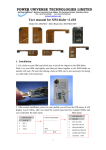
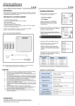
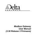
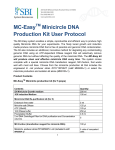
Using Yaskawa E7U and P7U VFDs with Delta Controls’
DAC-322-MOD-YSD (UUX000373) BACnet/MODBUS Gateway
1. INTRODUCTION
The following information describes utilizing the Yaskawa E7U and P7U Variable Frequency Drives with
Delta Controls’ DAC-322-MOD-YSD BACnet to Modbus RTU gateway (Yaskawa part number
UUX000373) to achieve BACnet control, monitoring and parameter access. This document contains the
general setup, connections, drive parameters and gateway objects available to the E7U and P7U drives.
2. INTENDED AUDIENCE
This document assumes that the reader is familiar with Yaskawa E7U and P7U Drives, Delta Controls’
DAC-322-MOD-YSD gateway (UUX000373), BACnet, BACnet MS/TP and RS485.
3. REFERENCES
Yaskawa E7 Drive User Manual -- TM.E7.01
Yaskawa E7 Drive Programming Manual -- TM.E7.02
Yaskawa P7 Drive User Manual -- TM.P7.01
Yaskawa P7 Drive Programming Manual -- TM.P7.02
Delta Controls’ DAC-322 Installation Guide
4. TERMS
BACnet
Building Automation Control network
Modbus RTU
A subset of the Modbus Protocol.
In this case, functions 0x03, 0x06, 0x08 and 0x10 are supported.
MS/TP
Master/Slave Token Passing
Yaskawa Electric America, Inc.
www.yaskawa.com
AN.AFD.11 Page 1 of 8
08/15/2008
Rev: 08-08
5. GENERAL SETUP
The figures below show a general system and its connections. This was the system setup for this
application note and used to test the gateway.
Note: The control software listed in the figure below should not be considered as a Yaskawa endorsement of said software. The
software is listed as an example only.
Yaskawa E7U or P7U
Drive
Laptop running some
BACnet Protocol software,
such as
Delta's ORCAview or
Cimetrics' BACnet Explorer
24 Vac
Power
Supply
DAC-322-MOD-YSD
(UUX000373)
BACnet MS/TP
Modbus RTU
Figure 1, General System Layout
Figure 2, E7U and P7U Drive Connections
Yaskawa Electric America, Inc.
www.yaskawa.com
AN.AFD.11 Page 2 of 8
08/15/2008
Rev: 08-08
24 Vac
24Vac
GND
BACnet
Connections
NET1
BACnet +
BACnet -
Address DIP
Switches
DAC
Inputs
Yaskawa E7U or P7U
Modbus RTU
Connections
NET2
R-/SR+/S+
DAC
Service Port
DAC
Outputs
Ground
Figure 3, DAC-322 (UUX000373) Connection Detail
Make sure all power is disconnected before making any connections.
* Note in this example a Delta DSM-RTR router and Delta’s ORCAview software was used to interface to
the gateway.
The DAC-322 (UUX000373) requires an external 24 Vac power supply in order to function. The power
supply should be connected to the PWR connector on the top left of the gateway as shown in the figure
above. Refer to the DAC-322-MOD-YSD Installation and Application Guide for more detail on the power
supply.
Connect the wires from the drive’s R+/S+ and R-/S- terminals to the NET2 Rx and Tx terminals on the
gateway as shown in the figure above. Note that the polarity of the connections for NET1 and NET2 are
reversed. Shielded twisted pair wire should be used with the shield tied to the ground point only at the
gateway. Be sure to install the jumper wires between drive terminals R+ and S+ and between terminals Rand S-. Set switch S1 on the drive terminal assembly to OFF.
Connect the BACnet network wires to the NET1 Rx and Tx terminals on the top left side of the gateway.
Make sure to connect the BACnet “+” wire to the gateway “+” terminal and the BACnet “-“ wire to the
gateway “-“ terminal. Note that the polarity of the connections for NET1 and NET2 are reversed. Refer
to the Delta Controls’ documentation of the DAC-322-MOD-YSD for information on wiring and setting
up the gateway.
Yaskawa Electric America, Inc.
www.yaskawa.com
AN.AFD.11 Page 3 of 8
08/15/2008
Rev: 08-08
6. Gateway Setup
Set the ADDRESS dip switches to the desired node address of the gateway and install the jumper at J12
so that DNA is enabled.
The baud rates are defaulted to the values shown below. These may be changed, but require access to the
DAC service port. Consult Yaskawa or a Delta Controls representative to change these values from their
defaults.
NET 1 Baud (BACnet MS/TP): 76800
NET 2 Baud (Modbus RTU to Drive): 19200
From ORCAView Navigator select Find New Devices from the drop down menu of BACnet Protocol.
Both the router and the gateway should be displayed as devices*. The router will be displayed as a device
on the BACnet Protocol network and the gateway will be displayed as a Yaskawa E7 VFD device on the
router. Select Yaskawa E7 VFD from the list of displayed devices and Modbus Gateway from the list of
device objects displayed. From the Setup tab, check Enable and select the Port and Speed (baud rate) to
be used in communicating with the drive. Since NET1 is already used for the BACnet connection, select
NET2 for the Yaskawa E7 VFD port. Of the baud rates available, only baud rates of 9600bps and
19200bps are compatible with the drive. 19200bps was selected in this case.
Figure 4, DAC Gateway Modbus Gateway Setup
* If the gateway is not displayed, first check the power and network wiring. If the wiring is verified, the
baud rate selected of the BACnet MS/TP NET1 network in the router may not have been set correctly. Go
back to the router device, BACnet Settings object and try the various baud rates until the gateway is
displayed as a device.
Refer to the documentation specific to the router and gateway used for setup information.
Yaskawa Electric America, Inc.
www.yaskawa.com
AN.AFD.11 Page 4 of 8
08/15/2008
Rev: 08-08
7. Set Drive Parameters
The E7U and P7U drives communicate with the gateway utilizing an embedded Modbus RTU protocol to
map the BACnet objects to the appropriate drive registers and parameters. Be aware that a 2-wire, 3-wire
or user reset of the drive could cause the values of the parameters listed below to change. Make sure to
check these parameters as part of any troubleshooting.
The table below shows the drive parameters that affect communications with the gateway. Refer to the
E7U or P7U Drive User or Programming manuals for information on other parameters and their settings.
Table 1, E7U and P7U Communication Parameters
Drive
Parameter
Parameter Name
Value
b1-01
Reference Source
2
b1-02
Run Source
2
H5-01
Serial Comm Adr
1
H5-02
Serial Baud Rate
4
H5-03
Serial Com Sel
0
H5-04
Serial Fault Sel
3
H5-05
Serial Fault Detect
0/1
H5-06
Transmit WaitTIM
5
H5-07
H5-08
RTS Control Sel
Protocol Select
1
0
H5-09
CE Detect Time
2.0
Description
For BACnet network control of the drive frequency reference set b1-01 to 2.
If BACnet is used for monitoring only set b1-01 to either 0 or 1 as specified
in the application.
For BACnet network control of the drive run command set b1-02 to 2. If
BACnet is used for monitoring only set b1-02 to either 0 or 1 as specified in
the application.
Sets the address of the node that the gateway looks to communicate.
The baud rate should be set to 4 (19,200 bps). Some older gateway units
were programmed to communicate at 9,600 bps. Check the gateway setup to
determine the correct baud rate. Program H5-02 accordingly.
Parity should be set to 0 (none).
The Alarm Only selection (3) allows the drive to continue operation in the
event of a communications fault. If your application calls out for a stopping
method as a result of a communications fault, select 0, 1 or 2 as the
application requires.
Set to enabled or disabled as the application requires.
This value should not be changed unless told to do so by a Yaskawa
application engineer.
RTS must be enabled.
Memobus(Modbus) must be selected.
This value should not be changed unless told to do so by a Yaskawa
application engineer.
Yaskawa Electric America, Inc.
www.yaskawa.com
AN.AFD.11 Page 5 of 8
08/15/2008
Rev: 08-08
8. BACnet Objects Supported
The tables below list the BACnet objects that are implemented in the DAC-322-MOD-YSD
(UUX000373).
Table 2, BACnet Analog Values (AV’s)
BACnet
Object
AV1
AV2
AV3
AV4
AV5
AV6
AV7
AV8
AV9
AV10
AV11
AV12
AV13
AV14
AV15
AV16
AV17
AV18
AV19
AV20
AV21
AV22
AV23
AV24
AV25
AV26
AV27
AV28
AV29
AV30
Object Name
Command
Frequency
PI Setpoint
Analog Output 1
Analog Output 2
Multi Function Contact
Reference Selections
Drive Status
Fault Details
Data Link Status
Frequency Reference
Output Frequency
Output Voltage
Output Current
Output Power
Torque Reference
Sequence Input Status
Drive Status 2
Multifunction Digital Status
Main Circuit DC Voltage
PI Feedback Level
PI Input Level
PI Output Level
CPU Software Number
Flash Software Number
Communications Error Details
kVA Setting
Control Method
Acceleration Time (x10)
Deceleration Time(x10)
R/W
Parameter
W
W
W
W
W
W
W
R
R
R
R
R
R
R
R
R
R
R
R
R
R
R
R
R
R
R
R
R
W
W
n/a
n/a
n/a
n/a
n/a
n/a
n/a
n/a
n/a
n/a
U1-01
U1-02
U1-06
U1-03
U1-08
U1-09
U1-10
n/a
U1-11
U1-07
U1-24
U1-36
U1-37
U1-28
U1-14
U1-39
n/a
n/a
C1-01
C1-02
Parameter
Address
0001h
0002h
0003h
0007h
0008h
0009h
0010h
0020h
0021h
0022h
0023h
0024h
0025h
0026h
0027h
0028h
002Bh
002Ch
002Dh
0031h
0038h
0039h
003Ah
003Bh
003Ch
003Dh
003Eh
003Fh
0200h
0201h
BACnet BV
Reference
BV1 – BV11
BV12 – BV15
BV16 – BV19
BV20 – BV26
BV27 – BV41
BV42 – BV48
BV49 – BV64
BV65 – BV71
Yaskawa Electric America, Inc.
www.yaskawa.com
AN.AFD.11 Page 6 of 8
08/15/2008
Rev: 08-08
Table 3, BACnet Binary Values (BV's)
BACnet
Object
BV1
BV2
BV3
BV4
BV5
BV6
BV7
BV8
BV9
BV10
BV11
BV12
BV13
BV14
BV15
BV16
BV17
BV18
BV19
BV20
BV21
BV22
BV23
BV24
BV25
BV26
BV27
BV28
BV29
BV30
BV31
BV32
BV33
BV34
BV35
BV36
BV37
BV38
BV39
BV40
BV41
BV42
BV43
BV44
W
W
W
W
W
W
W
W
W
W
W
W
W
W
W
W
W
W
W
R
R
R
R
R
R
R
R
R
R
R
R
R
R
R
R
Active
Text
Forward
Reverse
Fault
ON
ON
ON
ON
ON
ON
ON
ON
ON
ON
Enable
ON
ON
ON
ON
ON
Running
Reverse
YES
Fault
Fault
ON
ON
Fault
Fault
Fault
Fault
Fault
Fault
Fault
Fault
Fault
Inactive
Text
Stop
Stop
Normal
OFF
OFF
OFF
OFF
OFF
OFF
OFF
OFF
OFF
OFF
Disable
OFF
OFF
OFF
OFF
OFF
Stopped
Forward
NO
Normal
Normal
OFF
OFF
Normal
Normal
Normal
Normal
Normal
Normal
Normal
Normal
Normal
BACnet AV
Reference
AV1
AV1
AV1
AV1
AV1
AV1
AV1
AV1
AV1
AV1
AV1
AV6
AV6
AV6
AV6
AV7
AV7
AV7
AV7
AV8
AV8
AV8
AV8
AV8
AV8
AV8
AV9
AV9
AV9
AV9
AV9
AV9
AV9
AV9
AV9
R
Fault
Normal
AV9
R
Fault
Normal
AV9
R
Fault
Normal
AV9
R
R
R
R
R
R
Fault
Fault
Fault
ON
ON
ON
Normal
Normal
Normal
OFF
OFF
OFF
AV9
AV9
AV9
AV17
AV17
AV17
Object Name
R/W
Command Forward Run
Command Reverse Run
Command External Fault
Command Fault Reset
Command ComNet
Command ComCtr
Command MFDI 3
Command MFDI 4
Command MFDI 5
Command MFDI 6
Command MFDI 7
MFCO BO1
MFCO BO2
MFCO Fault Contact Enable
MFCO Fault Contact
Reference Selection Input PI Setpoint
Reference Selection BDT S5 Input
Reference Selection BDT S6 Input
Reference Selection BDT S7 Input
Drive Status - Operation
Drive Status - Direction
Drive Startup Complete
Drive Status - Fault
Drive Status - Data Setting Error
Drive Status - MFDO1 Status
Drive Status - MFDO2 Status
Overcurrent Ground Fault
Main Circuit Overvoltage
Drive Overload
Drive Overheat
Fuse Blown
PI Feedback Reference Lost
External Error
Hardware Error
Motor Overload
PG Broken Wire Detected
Overspeed
Speed Deviation
Main Circuit Undervoltage Detected
Main Circuit UV
Control PS Error
Inrush Prevention Circuit Error
Missing Output Phase
MODBUS Comm Error
Operator Disconnected
Input Terminal S1
Input Terminal S2
MSDIT S3
Yaskawa Electric America, Inc.
www.yaskawa.com
AN.AFD.11 Page 7 of 8
08/15/2008
Rev: 08-08
Table 3, BACnet Binary Values (BV's)
BACnet
Object
BV45
BV46
BV47
BV48
BV49
BV50
BV51
BV52
BV53
BV54
BV55
BV56
BV57
BV58
BV59
BV60
BV61
BV62
BV63
BV64
BV65
BV66
BV67
BV68
BV69
BV70
BV71
Object Name
MSDIT S4
MSDIT S5
MSDIT S6
MSDIT S7
Drive Status
Zero Speed
Frequency Agree
Desired Frequency Agree
Frequency Detection 1
Frequency Detection 2
Drive Startup Completed
Low Voltage Detection
Baseblock
Frequency Reference Mode
Run Command Mode
Overtorque Detection
Frequency Reference Lost
Retrying Error
Error
MODBUS COMM Timeout
CRC Error
Invalid Data Length
Not Used
Parity Error
Overrun Error
Framing Error
Time Out
R/W
R
R
R
R
R
R
R
R
R
R
R
R
R
R
R
R
R
R
R
R
R
R
R
R
R
R
R
Active
Text
ON
ON
ON
ON
Running
YES
Agree
Agree
YES
YES
YES
YES
YES
Local
Local
Fault
Fault
Fault
Fault
Fault
Fault
Fault
Inactive
Text
OFF
OFF
OFF
OFF
Stopped
NO
Disagree
Disagree
NO
NO
NO
NO
NO
Communication
Communication
Normal
Normal
Normal
Normal
Normal
Normal
Normal
Fault
Fault
Fault
Fault
Normal
Normal
Normal
Normal
BACnet AV
Reference
AV17
AV17
AV17
AV17
AV18
AV18
AV18
AV18
AV18
AV18
AV18
AV18
AV18
AV18
AV18
AV18
AV18
AV18
AV18
AV18
AV26
AV26
AV26
AV26
AV26
AV26
AV26
Table 4, BACnet Multi-State Variables (MV's)
BACnet
Object
MV1
MV2
MV3
Object Name
R/W
Reference Operation Mode Select (b1-01)
Run Command Mode Select (b1-02)
Stop Mode Select (b1-03)
W
W
W
0
Operator
Operator
Ramp
1
Terminal
Terminal
Coast
State Text
2
Serial
Serial
DC Injection
3
Option
Option
Coast w/ Timer
Yaskawa Electric America, Inc.
www.yaskawa.com
AN.AFD.11 Page 8 of 8
08/15/2008
Rev: 08-08