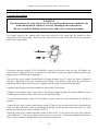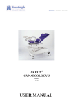
1
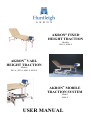
AKRON® FIXED
HEIGHT TRACTION
Models
900-A, 8900-8
AKRON® VARIHEIGHT TRACTION
Models
901-A, 902-A, 8901-8, 8902-8
AKRON® MOBILE
TRACTION SYSTEM
Model
8904-8
USER MANUAL
AKRON 900A, 901A, 902A, 8900-8, 8901-8, 8902-8, 8904-8
Contents
1.
2.
Introduction
2
Warnings, Cautions
General Warnings
2
2
Installation
3
4
3.
Operation
5-13
4.
Accessories – Operating Instructions
14-22
5.
Cleaning and Decontamination
23
24
6.
Troubleshooting
24
7.
Maintenance
25
8.
Warranty and Service
26
27
9.
Revision Status
27
10.
Technical Specification
28
"The
mark on this product demonstrates conformity
with the EC Directive 93/42/EEC."
1
AKRON 900A, 901A, 902A, 8900-8, 8901-8, 8902-8, 8904-8
1. Introduction
Always keep this Operating Manual available for reference.
Warnings & Cautions
WARNINGS
Warnings identify possible hazards in procedures or conditions which, if not correctly followed,
could result in death, injury or other serious adverse reactions.
CAUTIONS
Cautions identify conditions or procedures which, if not correctly followed, could result in equipment
failure or damage.
General Warnings
WARNINGS
Use only accessories that have been designed or approved for use with this couch.
Do not use electric couches in the presence of flammable gasses such as an
anaesthetic agent.
Maximum Load 180 Kg (396 lbs) distributed evenly.
Do not concentrate weight on either side of the table.
Plug acts as a disconnect device.
Do not allow children to play with the table at any time.
Adequately supervise children in the proximity of the table.
2
AKRON 900A, 901A, 902A, 8900-8, 8901-8, 8902-8, 8904-8
2. Installation
Adjustable Foot
WARNING
Lock castors before adjusting.
A)
Lock castors first.
B)
Adjust foot.
C)
Lock foot by tightening half nut.
WARNING
Do not insert the 2-pin mains connector directly into a 3-pin 13A mains outlet.
Always use the adapter provided.
Plug acts as a disconnect device.
Electric Models
Use adapter if 3 pin 13A plug is required.
(Order reference 5S0409Z)
Ensure mains supply cable is not stretched when connected.
Ensure, during table use, no obstacles are in its path.
Ensure hand / foot switch tubes or leads are not trapped by moving parts of the couch.
CAUTION
When not in use, switch table off.
3
AKRON 900A, 901A, 902A, 8900-8, 8901-8, 8902-8, 8904-8
2. Installation
Fixed Height Traction Table Assembly (900A, 8900-8)
WARNING
Ensure legs are secured correctly using supplied fittings, prior to use.
To assemble:
A)
Position legs up to the correct end of the table.
B)
Locate bolts through holes.
C)
Secure by adding washer and nut.
D)
Tighten until secure.
E)
Fix on nut caps.
4
AKRON 900A, 901A, 902A, 8900-8, 8901-8, 8902-8, 8904-8
3. Operation
Elevation Controls
WARNING
Safely position patient before elevating table.
Position all electrical cables away from the moving parts.
Position Hand/Foot switch where accidental operation is not possible.
Hydraulic Models
PUMP PEDAL TO
RAISE TABLE
Hydraulic Pedal
Electric Models (902A)
Press é to raise table.
Press ê to lower table.
Handswitch
AUF
Press é to raise table.
AB
Press ê to lower table.
Footswitch
5
LIFT PEDAL TO
LOWER TABLE
AKRON 900A, 901A, 902A, 8900-8, 8901-8, 8902-8, 8904-8
3. Operation
Foot Bar Switch
Press tube done to raise table
Lift tube up to lower table
Wheel Locking
WARNING
Lock couch wheels/castors prior to patient transfer or treatment.
The retractable castors are not designed for transportation of patients.
Disconnect and coil electrical cord away from moving parts prior to
repositioning table.
Castors (901A, 902A)
Castors Unlocked
Castors Locked
Breathing Hole and Plug
Remove plug for patient prone position
Press out from underneath
6
AKRON 900A, 901A, 902A, 8900-8, 8901-8, 8902-8, 8904-8
3. Operation
Head & Foot Sections
CAUTION
Support upholstery section while manually altering the angle.
Head Section Operating Lever
A)
Press lever UP to alter section angle.
B)
Support section when altering angle.
C)
Release lever to lock section in position.
Angles = +85° -18°
Foot Section Operating Lever
A)
Press lever UP to alter section angle.
B)
Support section when altering angle.
C)
Release lever to lock section in position.
Angles = +85° -0°
7
AKRON 900A, 901A, 902A, 8900-8, 8901-8, 8902-8, 8904-8
3. Operation
Sliding Frame (900A, 901A, 902A)
WARNING
Ensure when Pelvic and Thoracic Harnesses are in use, the Sliding Top Frame is
released before traction commences.
Sliding Frame Closed
Sliding Frame Open
A)
To release the top, release the lever located towards the head end of the table.
B)
This unlocks the ratchet mechanism and allows the frame to slide along inside the main frame.
C)
To lock, simply tighten the lever.
8
AKRON 900A, 901A, 902A, 8900-8, 8901-8, 8902-8, 8904-8
3. Operation
Fixed Traction Mounting Bracket (Model 2F1970Z)
The fixed traction mounting bracket comes as standard as part of the traction table. It is fitted to the foot
end of the table to secure the ATP9 Traction Machine.
WARNING
Ensure that the electrical cord from the ATP9 is coiled away from the rotating
Mounting Platform when in use.
G
B
D
H
F
E
D
C
J
A
Fitting Instructions
Locate bracket (item A) on to the traction table, by sliding onto the section at the foot end of the table.
Lock bracket in place using an M8 bolt and nut (items B & C), inserting two washers (item D) either side
of the bracket.
Two locking knobs (item E) are screwed into the support member positioned at the base of the top frame
(item F). Tightening these knobs will stabilise the bracket when traction procedures are in progress.
The ATP9 Traction Machine (item G) can then be clamped into place onto the support table platform
(item H). Refer to the ATP9 Traction Machine User Manual for the machine mounting procedure.
9
AKRON 900A, 901A, 902A, 8900-8, 8901-8, 8902-8, 8904-8
3. Operation
Fixed Traction Mounting Bracket (Model 2F1970Z)
Operating Instructions
To raise the support table platform (item H), unscrew the height adjustment clamp (item J) positioned on
the side of the bracket (item A).
To lock the platform, tighten the height adjustment clamp.
To lower the platform, unscrew the adjustment clamp, push down to the required position and tighten
clamp.
The platform also rotates freely to give the therapist the flexibility to manoeuvre the platform.
10
AKRON 900A, 901A, 902A, 8900-8, 8901-8, 8902-8, 8904-8
3. Operation
Mobile Traction Stand (8904-8)
WARNING
Check condition of straps. If worn out replace immediately.
Only use Huntleigh Akron Straps and Harnesses.
ATP9 Traction Machine
ATP9 Traction Machine Clamp
Height Adjustment Clamp
Upholstered Buffer Pad
Locking Castors
Retaining Straps
To raise the Traction Machine :A)
Rotate the height adjustment clamp anti-clockwise.
B)
Support the Traction Machine as it rises.
C)
Adjust to height required.
D)
Rotate the height adjustment clamp clockwise to secure at desired height.
11
AKRON 900A, 901A, 902A, 8900-8, 8901-8, 8902-8, 8904-8
3. Operation
Mobile Traction Stand (8904-8)
To secure the Mobile Traction System to the table :A)
Position the stand at the end of the table with the buffer pad against the upholstery.
B)
To adjust the buffer pad, simply release the clamp knob.
C)
Raise or lower the buffer pad to the desired height and re-tighten the clamp knob to secure.
D)
Secure the retaining straps around the table and the mobile unit.
E)
The castors on the Mobile Traction System must be locked to hold the unit in place.
Castors
WARNING
Lock table wheels/castors prior to patient transfer or treatment.
Castors Locked
Castors Unlocked
12
AKRON 900A, 901A, 902A, 8900-8, 8901-8, 8902-8, 8904-8
3. Operation
Counter Traction Straps (CT9000)
Two anchor brackets are provided for securing the thoracic counter traction straps at the opposite end of
the table to the mobile traction unit.
The brackets are held into position by tightening the grub screws onto the box section of the table.
The brackets must be fitted with the hole situated in the bar pointing outwards.
The large CT9000 strap is connected onto the anchor bracket by means of a dog clip, and the small
CT9000 strap is connected to the thoracic counter traction harness by means of a dog clip.
The pelvic Y belt is then attached to the ATP9 Traction Machine.
When connected, feed the large strap through the buckle and pull tight. The patient is then ready for
treatment to commence.
13
AKRON 900A, 901A, 902A, 8900-8, 8901-8, 8902-8, 8904-8
4. Accessories
ATP9
(ATP9)
Head Halter
(HH51)
ATP9
(ATP)
Head Halter
(HH51)
Cervipillo + Cover
(JC102 + CC103)
Thoracic Harness
(CT81UV)
Pelvic Harness
(PB61UV)
Counter Traction Straps
(CT9000)
Flexion Stool
(FS900)
Spreader Bar
(SC31)
When purchased as a Traction Package the above accessories are supplied as standard.
If only the table is purchased, any of the above accessories can be obtained in addition.
14
AKRON 900A, 901A, 902A, 8900-8, 8901-8, 8902-8, 8904-8
4. Accessories – Operating Instructions
ATP9 Traction Unit
WARNING
Before the ATP9 Traction Unit is used, please read the ATP9 User Manual, paying
particular attention to safety instructions, warnings and cautions.
Flexion Stool (Model FS900)
WARNING
The Flexion Stool is not to be used as a seat.
Only use on the table as a support under the calves of the legs.
To raise the stool…
A)
Rotate the knob under the upholstery section anti-clockwise.
B)
Adjust upholstery section to desired position.
C)
To secure the stool, rotate the knob clockwise.
15
AKRON 900A, 901A, 902A, 8900-8, 8901-8, 8902-8, 8904-8
4. Accessories – Operating Instructions
Traction Swivel Bracket and Mount (Model Option 8906)
WARNING
Always lock the swivel bracket before treatment commences.
Ensure that the electrical cord from the ATP9 is coiled away from any moving
parts of the swivel bracket.
Fitting Instructions
The swivel bracket is positioned at the foot end of the table and is fitted using a mounting bracket (item
A).
This is secured to the top frame (item B) using two bolts (item C), which are inserted into the holes on the
side of the top frame and secured by a nut and washer (items D) as shown.
The ATP9 Traction Machine (item E) can then be clamped into place on the support table platform (item
F). Refer to the ATP9 Traction Machine User Manual for the machine mounting procedure.
E
F
J
B
K
D
16
Installation
Details
G
A
H
C
16
AKRON 900A, 901A, 902A, 8900-8, 8901-8, 8902-8, 8904-8
4. Accessories – Operating Instructions
Traction Swivel Bracket and Mount (Model Option 8906)
Operating Instructions
To raise the support table platform, unscrew the height adjustment clamp (item G) positioned on the side
of the bracket (item H).
To lock the platform, tighten the height adjustment clamp.
To lower the platform, unscrew the adjustment clamp, push down to the required position and tighten
clamp.
The platform also rotates freely to give the therapist the flexibility to manoeuvre the platform.
The swivel bracket (item H) allows the platform to swivel 180º and may be locked off centre for traction
procedures.
The bracket is locked into place by sliding the operating rod (item J) towards the index plate (item K).
This movement pushes a pin into the index plate and locks the bracket into place.
Sliding the operating rod towards the platform will unlock the bracket, allowing it to swivel freely.
17
AKRON 900A, 901A, 902A, 8900-8, 8901-8, 8902-8, 8904-8
4. Accessories – Operating Instructions
Cervical Sitting Unit (Model 8903)
WARNING
Check harnesses for wear before use. Worn and frayed harnesses should not be
used and should be replaced. Use only Huntleigh Akron harnesses.
Fitting Instructions
Raise the foot section to its highest position and remove the black plastic end caps on the top of the foot
frame section.
Insert the Cervical Unit (item A) fully into the top of the foot frame until the stops positioned on the base
of the cervical unit fit up against the end of the foot frame section.
Slide the cervical mast (item B) into the accessory frame socket positioned on the cervical unit, so that the
hook on the mast is pointing downwards and up against the socket.
Secure the mast to the cervical frame (item A) by tightening the knob (item C) on the top of the cervical
frame.
18
18
AKRON 900A, 901A, 902A, 8900-8, 8901-8, 8902-8, 8904-8
4. Accessories – Operating Instructions
Cervical Sitting Unit (Model 8903)
Fitting Instructions (Continued)
The overhead flexion pulley adjustment collar (item D) should then be placed over the cervical mast (item
B) and secured in the required position by tightening the knob on the side of the collar, making sure the
hook is pointing downwards.
Place a pulley (item E) on each of the hooks on the cervical unit and the flexion collar (item D).
Feed the extension cord (item F) through the pulleys from the head end and connect up to the Line-Tite
clamp (item G) by pulling the spring insert and inserting the rope into the ball bearing end of the clamp.
Releasing the insert will lock the cord into place.
The clamp is then connected to the Traction Machine (Item H) by means of the connecting ring on the
Line-Tite clamp.
A spreader bar (item J) can then be fixed to the hook on the end of the extension cord (item F) to
accommodate a head halter (model HH51) to support the patients head and neck.
19
AKRON 900A, 901A, 902A, 8900-8, 8901-8, 8902-8, 8904-8
4. Accessories – Operating Instructions
Cervical Sitting Unit (Model 8903)
Operating Instructions
The patient may now be seated against the foot section/backrest. Adjust the backrest to make the patient
comfortable.
Place the head halter over the patient’s head/neck area, so that the halter supports the head under the chin
and across the back of the head.
A cervical contour pillow (model JC102) should be placed under the neck and head for patient comfort.
To remove the slack from the extension cord using the ATP9 Traction Machine, proceed as follows:
1.
With the hold and rest timers set to zero, set the high force control to indicate 35Kg or less if
required.
2.
Set duration of treatment timer to 20 minutes or less if required.
3.
Push ‘START’ button to commence the first run.
4.
Push ‘STOP’ button when zero force is reached. This will take up all the slack which could not be
achieved manually.
Check the correct functioning of the ‘patient interrupt’ switch and pass it to the patient concerned.
The ATP9 Traction Machine should be switched off and the head halter removed after treatment. It is
advisable to allow the patient 5 to 10 minutes recovery before removal from the table.
A more detailed account of the operation of the ATP9 Traction Machine can be found in the ATP9 User
Manual.
20
AKRON 900A, 901A, 902A, 8900-8, 8901-8, 8902-8, 8904-8
4. Accessories – Operating Instructions
Traction Procedures
WARNING
Check harnesses for wear before use. Worn and frayed harnesses should not be
used and should be replaced. Use only Huntleigh Akron harnesses.
Be sure to lock the Rolling Section at the end of any traction procedure.
The unique design of the traction table allows the harnesses to be fitted after the patient has been
positioned on the traction table. This means the harnesses can be left on the table after each treatment,
ready for the next patient.
The thoracic harness (model CT 81UV) should be centred over the base of the rib cage. The tighter it is
drawn, the less slippage will occur in traction. Once the harness is properly tightened on the patient in the
supine position it need not be re-tightened.
The top of the pelvic harness (model PB61UV) should fit about 5cm (2") above the ileum, or higher if
necessary, depending on the bone structure of the patient. If the harness is placed on the patient in the
standing position, it may be necessary to re-tighten after the patient is positioned on the table.
Adjust the table height to that most suitable for the transfer of the patient.
If mobile, sit the patient on the centre section. In the lying (supine) position, the patient should be placed
so that the lower lumbar region is directly over the split in the table.
A cervical contour pillow (model JC102) should be placed under the neck and head of the patient for
comfort.
Connect the two large counter traction straps (model CT9000) to the brackets at the top of the head frame
using dog clips and slip the small straps through the buckle. Secure the end of the straps to the ‘D’ rings
on the top of the thoracic harness (model CT81UV).
Attach the hook on the Traction Machine (model ATP9) to the ‘D’ ring at the base of the pelvic harness
(model PB61UV). If the pelvic harness has moved up or to one side, it should be straightened and placed
back over the trochanter. Retighten the pelvic and thoracic harnesses.
21
AKRON 900A, 901A, 902A, 8900-8, 8901-8, 8902-8, 8904-8
4. Accessories – Operating Instructions
Traction Procedures (Continued)
Position the flexion stool (model FS900) under the calves of the legs of the patient and adjust the height
for optimum comfort. It may help the patient to relax if the knees are strapped together.
To remove the slack from the harnesses using the ATP9 Traction Machine proceed as follows:
1.
With the hold and rest timers set to zero, set the high force control to indicate 35 Kg or less if
required.
2.
Set duration of treatment timer to 20 minutes or less if required.
3.
DO NOT release the Rolling Top at this stage.
4.
Push ‘START’ button to commence the first run.
5.
Push ‘STOP’ button when zero force is reached. This will take up all the slack which could not be
achieved manually.
Release the rolling top by rotating the lever under the upholstery section, and treatment will commence.
After the first run, set the prescribed kilogram force. In the case of the ATP9, set the progressive mode
controls as desired or prescribed.
By waiting to let the machine take up the remaining slack first, the table should not open more than an
inch or so and will always return to a closed position at the end of each cycle.
If the rolling frame opens to 125mm or 150mm it indicates sufficient slack was not removed initially. To
correct the condition, push or slide the rolling section back under the patient whilst the machine is in the
hold mode.
Check the correct functioning of the ‘patient interrupt’ switch and then pass it to the patient with
instructions on its use.
The ATP9 Traction Machine should be switched off and the straps removed from the patient. It is
advisable to allow the patient 5 to 10 minutes recovery before removal from the table.
A more detailed account of the operation of the ATP9 Traction Machine can be found in the ATP9 User
Manual.
22
AKRON 900A, 901A, 902A, 8900-8, 8901-8, 8902-8, 8904-8
5. Cleaning and Decontamination
WARNING
Do not use Alkalis or other organic solvents for routine cleaning.
Replace torn or damaged vinyl immediately.
Always cover vinyl with fresh paper or sheet between patients.
If contamination is known or suspected always decontaminate couch before use.
Frequency of routine couch cleaning will depend on exact application.
CLEANING / DECONTAMINATION
Wear suitable protective clothing.
Disconnect mains supply.
Locate couch in a suitable cleaning area with castors disengaged or wheels locked.
A)
B)
C)
Using a clean damp cloth, warm water and soap carefully wipe couch from top to bottom, taking
care around electrical components.
Wipe couch carefully from top to bottom using a damp cloth and clean water.
Wipe couch carefully dry with clean paper towels from top to bottom.
If DECONTAMINATING then repeat steps a) to c) using a dilute Hypochlorite / warm water mixture
(10,000ppm) instead of warm water and soap.
Safely discard cleaning / decontaminating materials.
Wash hands thoroughly.
Put couch back into service.
23
AKRON 900A, 901A, 902A, 8900-8, 8901-8, 8902-8, 8904-8
5. Cleaning and Decontamination
Decontamination of Traction Straps
It is not recommended that the straps are laundered on a regular or routine basis as this will eventually
compromise the integrity of the material and associated Tac-Flex. However, under certain conditions, i.e.
when the straps become heavily soiled or when they are suspected or known to have been in contact with
an infectious organism, they can be laundered or decontaminated using one of the following methods.
General Wash
The straps should be washed separately, as the Tac-Flex will attract debris from other material which will
ultimately reduce its effectiveness.
The Tac-Flex should be joined prior to washing.
The straps may then be laundered in the normal fashion, at a temperature of approximately 71°C and
allowed to dry in ambient conditions.
After such wash, the straps should be thoroughly inspected prior to patient use. If deterioration is present
or the Tac-Flex fails to maintain integrity, the straps must be replaced.
Decontamination
(Eye protection and suitable clothing should be worn) Where contamination is known or suspected, the
surface of the straps should be sprayed liberally using a solution of Na DCC 1,000 ppm of a suitable
chlorine or Sodium hypochlorite 1,000 ppm, after removing excessive organic material. The straps
should then be air dried at ambient temperature and inspected (as above) prior to patient use.
6. Troubleshooting – Electric Actuator
Symptom
Actuator will not work
Actuator runs when Bar
is not pressed
(Foot Bar Switch)
Possible cause
Power disconnected
Action
Ensure mains supply is connected
Fuse blown
Replace fuse in socket
Hand/footswitch
disconnected
Out of balance system
Check that the hand/foot switch is fully
inserted into the actuator
Vent air tube by disconnecting from
actuator, then reconnect
If the problem persists consult your local Akron Supplier.
24
AKRON 900A, 901A, 902A, 8900-8, 8901-8, 8902-8, 8904-8
7. Maintenance
Check couch visually before use.
Carry out routine servicing every six months or more frequently if in heavy use.
Routine servicing or repair must only be performed by suitably qualified person.
WARNING
Before commencing any maintenance activity, disconnect the couch from the
electrical supply.
Plug acts as disconnect device.
Examine the couch for any signs of damage. Make sure that all nuts, bolts and other fasteners are tight.
Do not over tighten as this may cause binding.
Upholstery fasteners should be checked, tightened or replaced if necessary.
Check section hinge pins to ensure that no pin protrudes.
Check gas strut controls, throughout the full range of movement for locking and assistance.
Check hydraulic couches for smooth operation and signs of leakage.
WARNING
All electrical checks should be performed by a suitably qualified and licensed
electrician.
Neither BLUE or BROWN wires are to be connected to the earth terminal of a
three pin plug.
Examine the flexible cables for cuts, abrasions, kinking or other deterioration and replace if necessary.
Ensure that the power supply connector plug is securely attached.
Check mains plug connections are tight and fuse is correctly rated (5A).
25
AKRON 900A, 901A, 902A, 8900-8, 8901-8, 8902-8, 8904-8
8. Warranty and Service (UK only)
Huntleigh Akron’s standard terms and conditions apply to this couch. A copy is available upon request.
These contain full details of warranty terms and do not limit the statutory rights of the consumer.
For service or maintenance please contact:
Service Department
Huntleigh Healthcare
310-312 Dallow Road
Luton
Beds
LU1 1TD
Telephone: 01582 745700
Fax:
01582 745869
For information on this product, or any other Huntleigh Akron product, please contact:
Huntleigh Akron
1 Farthing Road
Ipswich
IP1 5AP
Telephone: 01473 461042
Fax:
01473 462924
Huntleigh Akron T/A a Division of Huntleigh Nesbit Evans Limited
A Member of the Huntleigh Technology PLC Group of Companies
© Huntleigh Technology PLC 2001.
If for any reason your couch is being returned, please inform Huntleigh Akron prior to sending, and:
1.
2.
3.
4.
Clean the product, as described in the cleaning section.
Pack it in suitable packing.
Attach the decontamination certificate (or other written statement declaring that the product has
been cleaned) to the outside of the package.
Mark the package “Service Department”.
Manufactured in the UK by Huntleigh Akron. As part of the ongoing development programme this
company reserves the right to modify specifications and materials of this couch without notice.
26
AKRON 900A, 901A, 902A, 8900-8, 8901-8, 8902-8, 8904-8
8. Warranty and Service (UK only)
Huntleigh Akron’s standard terms and conditions apply to this couch. A copy is available upon request.
These contain full details of warranty terms and do not limit the statutory rights of the consumer.
For service, maintenance and any questions regarding this, or any other Huntleigh Akron Product, please
contact:
Huntleigh Akron
1 Farthing Road
Ipswich
Suffolk
IP1 5AP.
England
Telephone:
+44 (0) 1473 461042
Fax:
+44 (0) 1473 462924
Huntleigh Akron T/A a Division of Huntleigh Nesbit Evans Limited
A Member of the Huntleigh Technology PLC Group of Companies
© Huntleigh Technology PLC 2001.
If for any reason your couch is being returned, please inform Huntleigh Akron prior to sending and:
1.
2.
3.
4.
Clean the product, as described in the cleaning section.
Pack it in suitable packing.
Attach the decontamination certificate (or other written statement declaring that the product has been
cleaned) to the outside of the package.
Mark the package “Service Department”.
Manufactured in the UK by Huntleigh Akron. As part of the ongoing development programme this
company reserves the right to modify specifications and materials of this couch without notice.
9. Revision Status
900A, 901A, 902, 902A, 8900-8, 8901-8, 8902-8, 8904-8
PAGES
ALL PAGES
ALL PAGES
PAGES 27 & 28
PAGE 2
ISSUE
UM - 01
UM - 02
UM - 03
UM - 04 (DCN958)
WRITTEN
S.Rees
S.Rees
J. Austin
J. Barker
27
DATE
11/06/98
07/12/98
15/11/99
30/10/00
AKRON 900A, 901A, 902A, 8900-8, 8901-8, 8902-8, 8904-8
10. Technical Specification
Head Length (cm)
Mid Length (cm)
Foot Length (cm)
Width (cm)
Overall Length (cm)
Height Range (cm)
900A
901A
902A
8904-8
70±1.5
14±1.5 + 22±1.5
92±1.5
70±1.5
202±3 - 212±3
65±1.5
70±1.5
14±1.5 + 22±1.5
92±1.5
70±1.5
202±3 - 212±3
56±1.5
102±1.5
180 Kg
Hydraulic
70±1.5
14±1.5 + 22±1.5
92±1.5
70±1.5
202±3 - 212±3
56±1.5
102±1.5
180 Kg
Electric
43±1.5
53±1.5
80±1.5
120±1.5
-
Max. Load Weight
Elevation Control
180 Kg
-
Electrical Data 230v
Actuator
Internal Fuse Rt
Current
Power
Mains Plug Fuse Rt (UK)
220-240v
T1.6A x 1
1.6A
480W
5.0A x 1
Electrical Data 115v
Actuator
Internal Fuse Rt
Current
Power
115v
F4.0A x 1
3.3A
380W
IEC 601-1 Classification
Check serial number label for classification
230v
115v
115v
Double Insulated
Double Insulated
Class 1
Type B equipment
Type B equipment
Type B equipment
Attention consult this
manual
Attention consult this
manual
Attention consult this
manual
28
AKRON 900A, 901A, 902A, 8900-8, 8901-8, 8902-8, 8904-8
29
AKRON 900A, 901A, 902A, 8900-8, 8901-8, 8902-8, 8904-8
30
AKRON 900A, 901A, 902A, 8900-8, 8901-8, 8902-8, 8904-8
31
AKRON 900A, 901A, 902A, 8900-8, 8901-8, 8902-8, 8904-8
32
Huntleigh Akron, 1 Farthing Road, Ipswich, Suffolk, IP1 5AP, England
Tel: +44 (0) 1473 461042
Fax: +44 (0) 1473 462924
792-055-04