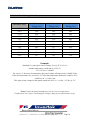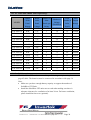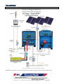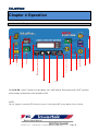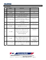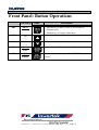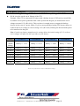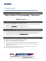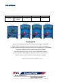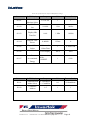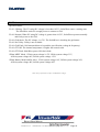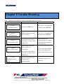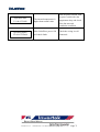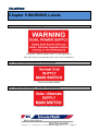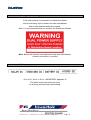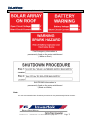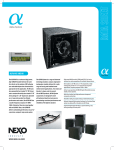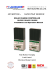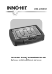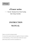
1
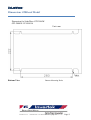
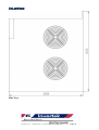
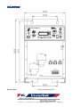
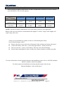
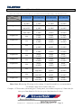
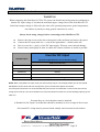
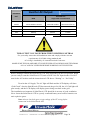
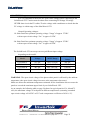
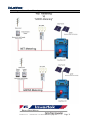
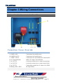
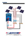
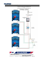
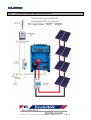
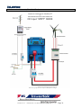
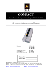
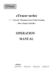
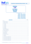
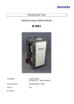
SOLARWORX®
Rich Electric Co.
“SolarWorx GTI” User Manual V100412 Copyright 2010
Page 2
SOLARWORX®
Table of CONTENTS
Introduction.....................................................................................................................................
Features...................................................................................................................... 8
About SolarWorx Grid-Tied Inverter .................................................................... 9
Specifications ........................................................................................................... 11
Dimensions............................................................................................................... 13
Chapter 1 Installation.....................................................................................................................
1.10 Box Contents.................................................................................................... 17
1.11 Location ........................................................................................................... 17
1.12 Front Panel ...................................................................................................... 18
1.13 Requirements................................................................................................... 18
1.14 Connection of GTI to Battery Bank ............................................................ 19
1.15 Connection of GTI to other DC Sources (MPPT)........................................ 20
1.16 DC Cable Size Chart....................................................................................... 21
1.17 DC Circuit Breaker Size Chart………………………...……………..……..22
1.18 Connection to AC Cabling ............................................................................. 23
1.19 Initial Start Up ................................................................................................ 24
1.20 MPPT Voltage ................................................................................................. 25
1.21 Solar Panel Voltage (VOC) Temperature Chart ......................................... 26
1.22 PV Table 2100 - 2400 watt.............................................................................. 27
1.23 PV Table 1400 - 2000 watt.............................................................................. 28
1.24 Parallel Connection......................................................................................... 28
1.25 Three Phase Operation................................................................................... 29
1.26 Anti-Islanding.................................................................................................. 29
1.27 Remote Control Panel……………………………………………………..…29
1.28 Ventilation (Standard Single Unit)…………………………………………...30
1.29 Ventilation (Optinal Fan Cover).................................................................... 30
1.30 Ventilation (Multible or 3-Phase Appliaction) ............................................. 30
Rich Electric Co.
“SolarWorx GTI” User Manual V100412 Copyright 2010
Page 3
SOLARWORX®
Chapter 2 Net Verse Gross Metering............................................................................................
2.10 Net Metering.................................................................................................... 31
2.11 Gross Metering................................................................................................ 31
2.12 Diagram Net Versus Gross Metering............................................................ 32
Chapter 3 Wiring Connection........................................................................................................
3.10 Lower Front Panel Connection for SolarWorx GTI ................................... 33
3.11 Battery Connection Schematic....................................................................... 34
3.12 Connection Schematic - Multi Cable Solar Connection.............................. 35
3.13 AC Three Phase Connection Schematic…………………………….………36
3.20 Connection Schematic - Basic Solar Grid Feed………………...…………..38
3.21 Connection Schematic - Wind Grid Feed……………………..………….…39
3.22 Connection Schematic - Hydro Grid Feed…………………..……………...40
3.23 Connection Schematic - Battery Mode Grid Feed………………...……….41
3.24 Connection Schematic - Combi Back-Up with Grid Feed…………..……..42
3.25 Connection Schematic - Grid Hybrid Battery Mode………..……………...43
3.26 Connection Schematic - Solar MPPT Combi-Grid Hybrid…...…….……...44
3.27 Connection Schematic - Combi-Grid Multi Hybrid…………………..….…45
3.28 Connection Schematic - Remote Off Grid system………………………......46
3.29 Connection Schematic - Combi-Grid Hybrid Gross Metering………...…..47
3.30 Connection Schematic - Combi-Grid Hybrid Net Metering………….....…48
Chapter 4 Operation.......................................................................................................................
4.10 Front Panel Display ........................................................................................ 49
4.20 Front Panel Button Operations ..................................................................... 51
4.30 Main Menu ...................................................................................................... 52
4.40 Main Menu: Programing "Operation" ........................................................ 53
Rich Electric Co.
“SolarWorx GTI” User Manual V100412 Copyright 2010
Page 4
SOLARWORX®
Chapter 5 Programming ................................................................................................................
A Group: Initialize.................................................................................................... 55
B Group: General ..................................................................................................... 57
O Group: Operator................................................................................................... 59
P Group: Communication........................................................................................ 61
Chapter 6 Combi-Grid. .............................................................................................................. 63
6.10 Combi-Grid Diagram……….…………………………………………………..64
Chapter 7 Constants List............................................................................................................ 65
Chapter 8 Trouble Shooting Table............................................................................................ 70
Chapter 9 Warning labels……………………………………………………………………….73
Rich Electric Co.
“SolarWorx GTI” User Manual V100412 Copyright 2010
Page 5
SOLARWORX®
Appendix A: EMC for SolarWorx® GTI
Appendix B: C-Tick for SolarWorx® GTI
Appendix C: AS 4777 & AS/NZS 3100 for SolarWorx® GTI
Introduction
Rich Electric Co.
“SolarWorx GTI” User Manual V100412 Copyright 2010
Page 6
SOLARWORX®
Rich Electric Co.
“SolarWorx GTI” User Manual V100412 Copyright 2010
Page 7
SOLARWORX®
SOLARWORX
®
GTI-2000
Features:
¾ Hybrid Grid-Tied Inverter
¾ Continuous Output Power Rating without de-rating at up to 50℃ ambient temperature.
¾
¾
¾
¾
¾
¾
¾
¾
DC Battery input
Solar, Wind and Hydro MPPT DC input*
Maximum Power Point Tracking (MPPT),
Combi Connect, offering True Hybrid interactivity.
Direct feed connection
Solar input capacity up to a 2400Watts.
Remote control replica of main control panel with LCD display*.
Power Stack for increased power
- Need more power?
Just keep stacking!
*Requires optional accessories, please see installation section for more information.
About SolarWorx® Hybrid Grid-Tied Inverter:
Introduction
The SolarWorx GTI can operate as a true Hybrid power system were power produced from your
solar panels, wind generator or hydro system can be sent back into the grid for a credit, however,
Rich Electric Co.
“SolarWorx GTI” User Manual V100412 Copyright 2010
Page 8
SOLARWORX®
authorisation from your electricity provider is required. The system can also operate as a standalone
power system when connected to the SuperCombi® or CombiPlus®, allowing you to power your
home during a grid failure or for an independent “Off-Grid” setup. When connected with the
SuperCombi®, power can be topped up from the grid supply during the “Off Peak Rate” if you don’t
have enough being produced from your panels. Alternatively, for “Off-Grid systems, a backup
generator can be automatically started to help support the homes power needs.
The SolarWorx® GTI is a highly reliable Grid-Tied Inverter and its most critical feature is to
maximise the harvest energy from the PV array by using the advanced technology of Maximum
Power Point Tracking (MPPT). The SolarWorx® GTI can also be directly connected to a battery
allowing for even more flexibility. The system is available in four different models 12VDC, 24VDC,
48VDC and 96VDC nominal battery voltage inputs each have built-in programmable protection to
ensure the correct battery connection and disconnection voltages to avoid exhausting the battery.
A wide range of MPPT input array voltages and battery voltage inputs are available depending on
your application. The DC input of GTI-2000-12 may be wired in the range of 16.5-32VDC or
nominal battery voltage of 12VDC, the DC input of GTI-2000-24 may be wired in the range of
33-64VDC or nominal battery voltage of 24VDC. The DC input of GTI-2000-48 may be wired in the
range of 66-128VDC or nominal battery voltage of 48VDC and the DC input of GTI-2000-96 may
be wired in the range of 132-226VDC or nominal battery voltage of 96VDC.
SolarWorx® GTI may not only be used in solar systems but also in wind or hybrid systems. With
respect to these systems it is normally required to use an optional turbine controller. The controller
with optional rectifier and braking unit for wind system is required to control and stop the control
from overload condition caused by excessive wind speeds.
SolarWorx® GTI is very flexible and can be configured in many different ways. It has been designed
to operate as a standalone basic grid feed, through to a truly interactive hybrid power management
system. By combining the SolarWorx® GTI with the SuperCombi® or CombiPlus® you can now
have the benefits of a complete hybrid power system. The power being generated from the solar
Array, wind or hydro is fed into the SolarWorx® GTI where it is then transferred into an AC supply.
The power is then connected to the AC output of the SuperCombi® or CombiPlus® creating an off
Rich Electric Co.
“SolarWorx GTI” User Manual V100412 Copyright 2010
Page 9
SOLARWORX®
grid power system, (Combi-Grid). The power from the SolarWorx® GTI is either sent to the
SuperCombi® or CombiPlus® to recharge the battery bank or can be used in conjunction with the
Combi’s power to help support the household loads. Please Note: Some Combi-Grid features maybe
limited please see page 62 for more details.
For example if we used a SolarWorx® GTI-2000 (2000Watts) and connected it to the SuperCombi®
SC-3000 (3000Watts), the output from both units can be combined together to support loads of up to
5000Watts. When the AC load is lower than the output of the GTI the excess power is sent back into
the SuperCombi to recharge the batteries. Once the Batteries are full, and the system is connected to
the mains grid, the excess power is then sent back into the grid for a credit.
The hybrid design allows you to operate your home during a black out and take advantage of the
power being generated from the solar array unlike many conventional Grid-Tied Systems.
When connecting the SolarWorx® GTI to the SuperCombi® you can also take advantage of topping
up you batteries during the “Off Peak” rate offered by many electricity providers these days.
This offers home owners and businesses even more savings on their electricity bills as well as the
comfort of having power during a black-out.
Multiple SolarWorx® GTI units can be connected together with a number of SuperCombi® or
CombiPlus® units offering power systems of up to 180KW.
Please carefully read through this manual and all the installations instruction and wiring before
beginning installation of your SolarWorx® GTI. The protection and installation equipment must
comply with the local codes. The rated fuses, breakers and external lightning protection should be
installed along with your SolarWorx® GTI.
A Truly Interactive Hybrid Power System.
Specifications
MODEL
Rich Electric Co.
12 Volt System
GTI-2000-12X (1)
24 Volt System
GTI-2000-24X
“SolarWorx GTI” User Manual V100412 Copyright 2010
Page 10
SOLARWORX®
48 Volt System
GTI-2000-48X
96 Volt System
GTI-2000-96X
Ventilation
Fan Forced cooling
Temperature
–
Operation
-10℃~ +45℃
–
Storage
-25℃~ +80℃
Protection
a. Output short circuit
9
b. Over load
9
c. Battery voltage too high
9
d. Battery voltage too low
9
e. DC input voltage too high
9
f. DC input voltage too Low
9
Transformer
(105℃)
Electronic & Powerstage
(70℃)
Humidity
0~95% (non condensing)
Combi Connect
9
Direct Feed
9
Anti-Islanding
(less than 10 msec)
Direct Battery Connection
9
3-Phase Capacity
9
Parallel Operation
9
Remote Control Port
9
Extension Port for PC Connection
9
Please note specifications are subject to Manufactures changes.
AC OUTPUT
Output Voltage
205-270V
Cont. Power Output @ 50℃ (W)
2000Watt
Under 50℃ (cosθ=1.0)
(No derate 50℃ )
Power Output Over 70℃
(Shutdown)
Maximum Power (W)
Maximum Efficiency (%)
Rich Electric Co.
2200Watt
86/90/94/96
“SolarWorx GTI” User Manual V100412 Copyright 2010
Page 11
SOLARWORX®
Please note specifications are subject to Manufactures changes.
DC INPUT
Maximum DC Input Voltage (VDC)
40V / 80V / 130V / 230V
Maximum Input Current(A)
180A / 90A / 45A / 22A
Input Voltage operating Range (VDC)
MPPT Mode
Input Voltage operating Range (VDC)
Battery Mode
16.5-32V / 33-64V / 66-128V / 132-226V
10-16V / 20-32V / 40-64V / 80-128V
Battery Voltage Default (VDC)
(1)
12V / 24V / 48V / 96V
X should be 1, output voltage = 102-135 VAC or 2, output voltage = 205-270 VAC
Eg. GTI-2000-121= 110VAC Model and GTI-2000-122 = 230VAC Model.
Specifications subject to change
AC INPUT
Detection Time AC Input Fault
<10 msec.
102 VAC - 135VAC
Normal AC Input Range
205VAC – 270VAC
Trip Level AC Low Input
Trip Level AC High Input
Min.~ Max. Frequency Range
110v Model
230v Model
101 VAC
110v Model
204VAC
230v Model
136 VAC
110v Model
271 VAC
230v Model
50 ± 1 Hz / 60 ± 1 Hz
MECHANICAL
Cabinet / Protecting Class
Dimension (HXWXD)
Aluminum / IP20
368 x 256 x 424 mm
Weight (kgs)
26 kgs
Dimensions
Rich Electric Co.
“SolarWorx GTI” User Manual V100412 Copyright 2010
Page 12
SOLARWORX®
Dimensions 2000watt Model
Dimension for SolarWorx GTI 2000W
GTI-2000W-12/24/48/96
Unit: mm
Bottom View
Rich Electric Co.
Bottom Mounting Holes
“SolarWorx GTI” User Manual V100412 Copyright 2010
Page 13
SOLARWORX®
Side View
Rich Electric Co.
“SolarWorx GTI” User Manual V100412 Copyright 2010
Page 14
SOLARWORX®
Front View
Backside Mounting Holes
Rich Electric Co.
“SolarWorx GTI” User Manual V100412 Copyright 2010
Page 15
SOLARWORX®
Chapter 1 Installation
This product should be installed by a qualified electrician.
ALL AC WIRING MUST BE CARRIED OUT BY A LICENSED
ELECTRICIAN AND MUST CONFORM TO AS3000 & AS4777
WIRING REGULATIONS OR RELEVANT STANDARDS
AS4777 states all the requirements for protection and isolation
when connecting inverters with the grid and all systems
shall be installed in accordance with that standard.
AS5033 states all the requirements for
protection and isolation within the PV array and all systems
shall be installed in accordance with that standard.
All cabling must be sized in accordance with
AS/NZS 3000 and AS/NZS 3008.
Cable losses between the PV array and the inverter should
never exceed 5% to maximise system output power.
For other regions, the installation and wiring should comply with relevant
National Standards, Codes and Practices.
Rich Electric Co.
“SolarWorx GTI” User Manual V100412 Copyright 2010
Page 16
SOLARWORX®
1.10 Box Contents
z SolarWorx GTI
z User Manual
z Warranty Card
z Bag Containing connection items,
z Four M6 mounting bolts (including spring washers)
z Two DC terminals and casing
1.11 Location
This product must be installed in a dry and well-ventilated area.
There should be a clear space of at least 20 cm around the appliance for cooling.
Excessively high ambient temperature will result in the following
z
z
z
Reduced service life
Reduced output current
Reduced peak capacity or shutdown of the inverter
Never position the inverter directly above the batteries.
SolarWorx GTI is suitable for wall mounting. The back and the bottom of the enclosure
has holes for wall mounting purposes.
Rich Electric Co.
“SolarWorx GTI” User Manual V100412 Copyright 2010
Page 17
SOLARWORX®
1.12 Front Panel
The front of SolarWorx GTI must remain accessible after installation. Ensure the AC and DC input
cables are fitted with fuses or circuit breakers. Try and keep the distance between the product and
battery to a minimum in order to minimise cable voltage losses.
The system should always be earthed for lightning and to reduce the risk of accidental short circuits.
Earthing the DC power wiring is not normally required. If the system is installed in a lightning prone
area, then protection for the earthing of the DC wiring may be needed.
DC Earth cables must be capable of carrying the battery fault current and tripping the battery fuse
before the cabling fails.
A Battery Fuse or Circuit Breaker is required at all times; Never connect the SolarWorx GTI directly
to the battery or solar panel without a Fuse or Circuit Breaker. The main Fuse or Circuit Breaker
should be connected as close to SolarWorx GTI as possible for easy accessibility.
If the batteries are not earthed, then protection should be provided on both the Positive and Negative
sides of the battery.
NOTE: The DC cabling should always be kept separate or be seperated from any of the AC cabling.
1.13 Requirements
z
Screwdrivers for removing the lower-front panel and connecting AC input.
z
2x DC input cables (ensure DC input cables are correctly sized).
z
Insulated box spanner (12 mm) for securing the DC terminal nuts.
z
Twin and Earth power cable for AC cabling.
Rich Electric Co.
“SolarWorx GTI” User Manual V100412 Copyright 2010
Page 18
SOLARWORX®
1.14 Connection of GTI to Battery Bank
When operating in Battery Mode Ensure you have enough battery capacity to be able to operate
your SolarWorx® GTI to its full capacity.
Model
GTI-2000-12X
GTI-2000-24X
GTI-2000-48X
GTI-2000-96X
Minimum Battery
Capacity (Ah)
400Ah
200Ah
100Ah
50Ah
Recommended
Cable Size
50 mm2
0 AWG
10mm2
8 AWG
2.5 mm2
14AWG
1.5 mm2
18 AWG
Item
NOTE: Consult your battery manufacturer for correct battery sizing for your application.
Battery cable sizes are based on recommended cable length of 2 meters. Longer cable lengths will
require large cable sizes.
Always use an insulated box spanner in order to avoid shorting the battery.
Never short the battery cables!
z
z
z
z
Remove the four screws at the lower-front panel of the enclosure and remove the panel.
Connect the battery cable: the + (red) on the right and the – (black) on the left.
Don’t reverse the (+) and (-) of the battery. This may cause internal damage.
Secure battery nuts tightly in order to reduce the contact resistance as much as possible.
For more information on battery bank enclosures and installations please refer to AUS/NZ standards
AS2676, AS4509, AS3010 & AS4086.
For other regions, the installation and wiring should comply with relevant
National Standards, Codes and Practices.
Rich Electric Co.
“SolarWorx GTI” User Manual V100412 Copyright 2010
Page 19
SOLARWORX®
1.15 Connection of GTI to Other DC Sources (MPPT)
When operating in MPPT Mode, ensure your DC cabling is of adequate size and rated to the
correct voltage to be able to operate your SolarWorx GTI to its full capacity.
Note: The table on page 21 is based on a single run of cable. If you are connecting multiple PV
strings, you can use multiple cables of smaller sizes and then connect them at the inverter,
Each cable will need to be protected with an appropriate rated fuse or circuit breaker.
Please take note of the correct cable sizing. We recommend a Maximum cable loss of 3%.
The AS/NZ 3000 and AS/NZ 3008 state cable losses should never exceed 5%.
During installation of the solar array it is advisable, if possible, to cover the solar panels (during cabling)
to help reduce the output voltage and current being generated by the modules.
It could be dangerous if a person was to come in contact with the positive and negative outputs of the
solar array , especially when the output voltage are greater than 120V DC.
All Solar Panel installations should be in accordance with AS/NZS5033:2005 Installation of PV Arrays.
Rich Electric Co.
“SolarWorx GTI” User Manual V100412 Copyright 2010
Page 20
SOLARWORX®
1.16 DC Cable Size Chart (GTI to Other DC Sources)
Please Note: Cable Chart is based on Max power of 2400watts and normal MPPT voltage, with cable losses of 3%.
Model
GTI-2000-12X
GTI-2000-24X
GTI-2000-48X
GTI-2000-96X
Length 6m
70 mm2
00 AWG
16 mm2
6 AWG
4mm2
12 AWG
1.5 mm2
16 AWG
Length 8m
95 mm2
000 AWG
25 mm2
4 AWG
6mm2
10 AWG
1.5 mm2
16 AWG
Length 10m
120 mm2
0000 AWG
35 mm2
2 AWG
10 mm2
8 AWG
2.5 mm2
14 AWG
NA
35 mm2
2 AWG
10 mm2
8 AWG
2.5 mm2
14 AWG
50 mm2
10 mm2
2.5 mm2
0 AWG
8 AWG
14 AWG
2
NA
50 mm
0 AWG
2
16 mm
6AWG
4 mm2
12 AWG
NA
50 mm2
0 AWG
16 mm2
6 AWG
4 mm2
12 AWG
NA
70 mm2
00 AWG
16 mm2
6AWG
4 mm2
12 AWG
NA
70 mm2
00 AWG
16 mm2
6 AWG
4 mm2
12 AWG
NA
70 mm2
00 AWG
16 mm2
6 AWG
4 mm2
12 AWG
NA
95 mm2
000 AWG
25mm2
4 AWG
6 mm2
10 AWG
NA
95 mm2
000 AWG
25 mm2
4AWG
6 mm2
10 AWG
NA
120 mm2
0000 AWG
25 mm2
4 AWG
6 mm2
10 AWG
DC Cable
Length 12m
Length 14m
NA
Length 16m
Length 18m
Length 20m
Length 22m
Length 24m
Length 26m
Length 28m
Length 30m
Please Note: When using PV strings on low voltage 12v and 24v models it is recommended to
use multiple cable runs to reduce cable size.
Example: 1575watt solar system using 9x 175watt panels you could use 9x pairs of 2.5mm cable for
runs up to 24m (based on 5% loss) or up to 14m (based on 3% loss).
Rich Electric Co.
“SolarWorx GTI” User Manual V100412 Copyright 2010
Page 21
SOLARWORX®
1.17 DC Circuit Breaker Size Chart
WARNING:
When connecting the SolarWorx® GTI to PV system, the Solar Panel wiring must be configured so
that the DC input voltage is less than the maximum upper voltage limit of the SolarWorx® GTI
Solar Panel output voltage is affected by the solar cells operating temperature (panel temperature),
the number of panels per string (panels connection is series).
Always check string voltages before connecting to the SolarWorx GTI.
z
Remove the four screws at the lower-front panel of the enclosure and remove the panel.
Connect the DC input cable: the + (red) on the right and the – (black) on the left.
Don’t reverse the (+) and (-) of the DC input supply. This may cause internal damage.
Secure battery nuts tightly in order to reduce the contact resistance as much as possible.
z
z
z
Inverter DC Input
SolarWorx GTI®
(Recommended Maximum Circuit Breaker Rating)
MCB (Circuit Breaker)
Model
2000 Watt SolarWorx GTI
2000W‐12v
160Amp
2000W‐24v
80Amp
2000W‐48v
40Amp
2000W‐96v
20Amp (Requires Hi DC Voltage Breaker)
NOTE: When using MPPT DC input mode you will normally require a HI Voltage Breaker for the 24v, 48v &
96v Models. Please check with the manufacture of the circuit breaker before connection.
For solar panel protection it is recommended that you base the circuit breaker current on the max current
rating of the PV array. The circuit breaker must never be rated more than the current handling capacity of the
cable run.
External fuses or circuit breakers must be installed.
A Double Pole DC Input Circuit Breaker should be mounted as close to input of the inverter.
All external DC wiring must be protected with suitably rated external circuit breakers.
Rich Electric Co.
“SolarWorx GTI” User Manual V100412 Copyright 2010
Page 22
SOLARWORX®
1.18
Connection of AC Cabling
Ensure the SolarWorx GTI is grounded for safety.
The main earth screw has been fitted at the bottom left side of the enclosure.
The AC terminal connection is located in lower-front panel of the enclosure:
The AC Supply (AC OUT) cable must be connected to AC OUT terminals,
Use a Twin and Earth power cable; refer to table on page 24 for correct AC cable sizes.
The AC output terminal connection is labeled “AC OUT”, The terminal points are indicated
clearly: From left to right “L” (phase), “N” (neutral), and “E” (earth).
External fuses or circuit breakers must be installed.
The AC output circuit breaker built in to the SolarWorx GTI is designed to protect the internal
wiring inside the unit only. Faults on sub circuits will not normally trip this breaker.
All external AC wiring must be protected with suitably rated external circuit breakers,
NOTE: RCD Earth Leakage protection must NOT be used for grid tie inverter systems that are
connected directly back to the grid.
MEN (Multiple Earth Neutral) must be maintained at all times.
For AC output protection we recommend the use of a Circuit Breaker (MCB).
For correct sizing see table on page 24.
Note: The cables shall be electrically protected in accordance with AS/NZS 3000 and AS/NZS 3008.
All cables used in the installation should be securely fixed in place to minimise any movement
of the cable in accordance with AS3000. Mechanical protection
of the cables shall be in accordance with AS/NZS 3000.
Rich Electric Co.
“SolarWorx GTI” User Manual V100412 Copyright 2010
Page 23
SOLARWORX®
Inverter AC Output
SolarWorx
GTI®
AC Cable Size
MCB
single Twin‐core and earth
2000Watt
Recommended
Model
Circuit Breaker Current
Enclosed conduit
Unenclosed free air
6m
10Amp
1.5mm
1.0mm
10m
10Amp
1.5mm
1.0mm
15m
10Amp
2.5mm
1.5mm
20m
10Amp
2.5mm
1.5mm
THE OUTPUT VOLTAGE FROM THE INVERTER IS LETHAL
For your safety ensure that all installations meet and comply with the relevant
requirements of AS3000 wiring standards and
AC wiring is installed by a Licensed Electrical Contractor.
MAKE SURE THE SOLARWORX GTI IS SWITCHED OFF AND DISCONECTED FROM
ALL AC AND DC SUPPLIES BEFORE WORKING ON THE SYSTEM!
1.19 Initial Start Up
Before starting to initiate the SolarWorx® GTI, keep all breakers in the OFF position. When
you are ready to start the SolarWorx® GTI, turn on ONLY the DC Input breaker. Do NOT
turn On the AC breaker until the instruction on LCD shows “Waiting” or “ No Utility”.
Turn On the AC Supply. The AC light will flash and the LCD display will show
“Grid Check” after the SolarWorx® GTI has assessed the grid is OK, the AC Grid light will
glow steady, and the LCD display will display power being sent back to the grid.
The installation environment of SolarWorx® GTI should be in an area of good ventilation.
Never locate the SolarWorx® GTI in a poorly ventilated battery area because batteries can
emit explosive gases.
Note: Always check the open circuit voltage of the PV string before
connection to the SolarWorx® GTI.
Rich Electric Co.
“SolarWorx GTI” User Manual V100412 Copyright 2010
Page 24
SOLARWORX®
1.20 MPPT Voltage
It is very important to check the PV open circuit voltage before connecting to the
SolarWorx® GTI. Caution must be taken when connecting HI Voltage PV strings.
NEVER short circuit the PV cables! Test the voltage with a multimeter to check that the
PV voltage is within range of the SolarWorx® GTI.
Normal Operating voltages:
12v Solar Panel has optimum operating voltage “Vmpp” of approx 17VDC
with an open circuit voltage “Voc” is approx 21VDC
24v Solar Panel has optimum operating voltage “Vmpp” of approx 35VDC
with an open circuit voltage “Voc” is approx 43VDC
The SolarWorx® GTI can accept can accept different input voltage
depending on the model:
Model
Voltage
MPPT Range
MAX input
Voltage
GTI-2000-12
12V DC
16.5V-32V DC
40V DC
GTI-2000-24
24V DC
33 V-64V DC
80V DC
GTI-2000-48
48V DC
66V-128V DC
130V DC
GTI-2000-96
96V DC
132V-226V DC
230V DC
Please note specifications are subject to Manufactures changes.
WARNING: The open circuit voltage of the photovoltaic panels is affected by the ambient
temperature (the open circuit voltage increases as the temperature decreases).
Make sure that at the minimum temperature estimated for the installation does not cause the
panels to exceed the maximum upper limit of your SolarWorx® GTI.
As an example, the following table on page 26 shows for typical panels of 36, 48 and 72
cells, the maximum voltage of each panel at different temperatures (assuming a nominal
open circuit voltage of 0.6VDC at 25°C and a temperature coefficient of 0.38% /°C).
Rich Electric Co.
“SolarWorx GTI” User Manual V100412 Copyright 2010
Page 25
SOLARWORX®
1.21 Solar Panel Voltage (Voc) Temperature chart
Min Panel Temp
36 Cell Solar Panel
Voltage (Voc)
48 Cell Solar Panel
Voltage (Voc)
72 Cell Solar Panel
Voltage (Voc)
+25°C
21.6
28.8
43.2
+20°C
22.0
29.4
44.0
+15°C
22.4
29.9
44.9
+10°C
22.8
30.5
45.7
+5°C
23.2
31.0
46.5
0°C
23.7
31.6
47.3
-5°C
24.1
32.1
48.2
-10°C
24.5
32.7
49.0
-15°C
24.9
33.2
49.8
-20°C
25.3
33.8
50.6
-25°C
25.7
34.3
51.4
Example:
Standard 12v panel open circuit voltage Voc @ 25°C is 21.6v
and the temperature coefficient is 0.38% /°C
21.6 x 0.38% = 0.08208
For every 1°C decrease in temperature, the panel voltage will increase by 0.08208 Volts
If the min temperature for you area is 5°C then the temperature difference would be 20°C
0.08208 x 20 = 1.6416 volts
The open circuit voltage for this panel would now be 21.6 + 1.6416 = 23.24v @ 5°C
Note: Consult the panel manufacturer for the correct temperature
Coefficient of Voc, before calculating the voltage rating of your photovoltaic array.
Rich Electric Co.
“SolarWorx GTI” User Manual V100412 Copyright 2010
Page 26
SOLARWORX®
1.22 PV Table 2100~2400W Solar Input Range
The SolarWorx® GTI 2000watt can except up to a maximum of 2400watts of
Solar Panels.
MODEL
Rated
Solar
Panel
Wattage
Rated
Solar
Panel
Voltage
Number of
Solar
Panels per
String
Number of
Strings
(Paralleled)
Total
Total
Number of Output
Solar
Wattage
Panels
GTI-2000-12
65W
12V
1
36
36
2340W
GTI-2000-12
80W
12V
1
30
30
2400W
GTI-2000-12
120W
12V
1
20
20
2400W
GTI-2000-12
175W
24V
NA
NA
NA
NA
GTI-2000-24
65W
12V
2
18
36
2340W
GTI-2000-24
80W
12V
2
15
30
2400W
GTI-2000-24
120W
12V
2
10
20
2400W
GTI-2000-24
175W
24V
1
13
13
2275W
GTI-2000-48
65W
12V
4
9
36
2340W
GTI-2000-48
80W
12V
4
7
28
2240W
GTI-2000-48
120W
12V
4
5
20
2400W
GTI-2000-48
175W
24V
2
6
12
2100W
GTI-2000-96
65W
12V
9
4
36
2340W
GTI-2000-96
80W
12V
9
3
27
2160W
GTI-2000-96
120W
12V
9
2
18
2160W
GTI-2000-96
175W
24V
4
3
12
2100W
NOTE: Maximum Voc
The maximum operating voltage of the SolarWorx ® GTI-2000-12 is 40VDC, of the
GTI-200-24 is 80VDC., of the GTI-200-48 is 130VDC.and of the GTI-200-96 is 230VDC.
Protection will be activated to shut down the unit when the operating voltage is higher.
Check the PV manufacturer’s data sheet with rated voltage and current as well as the current
and temperature coefficients. The rated Voc is measured at the temperature of 25℃ so when
calculated at lower temperature such as 0℃, typically a10% increase of the rated Voc will be
expected. At different temperature location of installation, the maximum Voc of the module
should be determined by the Voc voltage temperature coefficient, a series string voltage may
then be calculated.
Rich Electric Co.
“SolarWorx GTI” User Manual V100412 Copyright 2010
Page 27
SOLARWORX®
1.23 PV Table 1400~2000W Solar Input Range
MODEL
Rated
Solar
Panel
Wattage
Rated
Solar
Panel
Voltage
Number of
Solar
Panels per
String
Number of
Strings
(Paralleled)
Total
Total
Number of Output
Wattage
Solar
Panels
GTI-2000-12
65W
12V
1
24
24
1560W
GTI-2000-12
80W
12V
1
19
19
1520W
GTI-2000-12
120W
12V
1
13
13
1560W
GTI-2000-12
175W
24V
NA
NA
NA
NA
GTI-2000-24
65W
12V
2
12
24
1560W
GTI-2000-24
80W
12V
2
10
20
1600W
GTI-2000-24
120W
12V
2
7
14
1680W
GTI-2000-24
175W
24V
1
9
9
1575W
GTI-2000-48
65W
12V
4
6
24
1560W
GTI-2000-48
80W
12V
5
4
20
1600W
GTI-2000-48
120W
12V
4
3
12
1440W
GTI-2000-48
175W
24V
2
5
10
1750W
GTI-2000-96
65W
12V
9
3
27
1755W
GTI-2000-96
80W
12V
9
2
18
1440W
GTI-2000-96
120W
12V
8
2
16
1920W
GTI-2000-96
175W
24V
4
2
8
1400W
.
1.24 Parallel Connection
The SolarWorx GTI can be connected in parallel using multiple units, please see
page 45 & 46. The batteries must be connected in accordance with page 34.
Note:
•
Make sure you have enough battery capacity to support the number of
SolarWorx GTI Units.
•
Install the SolarWorx GTI units next to each other making sure there is
adequate clearance for ventilation of at least 20 cm. For better ventilation,
please install the fan cover (optional).
Rich Electric Co.
“SolarWorx GTI” User Manual V100412 Copyright 2010
Page 28
SOLARWORX®
1.25
3-Phase Operation
The SolarWorx GTI can be configured for use in a 2 or 3-phase applications see
page 36.
Note:
•
Make sure you have enough battery capacity to support all of the SolarWorx
GTI Units.
•
Install the SolarWorx GTI units next to each other making sure there is
adequate clearance for ventilation of at least 20 cm. For better ventilation,
please install the fan cover (optional).
•
The battery cables for each SolarWorx® GTI must be of equal in length
1.26 Anti-Islanding
The SolarWorx® GTI inverter will automatically disconnect from the utility grid when the
utility grid is out of voltage / frequency range, during a black-out (grid failure) or when the
inverter shuts down due to a fault condition. This is to guarantee protection for persons
operating on the utility grid, and in compliance with the AS4777 standards.
1.27 Remote Control Panel (RP-GTI)
The SolarWorx GTI can be operated remotely from remote port with the aid of a
remote control panel. For connection of a remote control panel, see page 33.
Note: The display panel and operation flow of the remote control panel is exactly
the same as the upper-front display panel.
Rich Electric Co.
“SolarWorx GTI” User Manual V100412 Copyright 2010
Page 29
SOLARWORX®
1.28 Ventilation (Standard Single Unit)
When the unit is installed in an Environment with good ventilation,
the fan cover is not needed.
1.29 Ventilation (Optional Fan Cover Application) “Single Unit Installed”
When the unit is installed nearby wall side which
blocks the airflow coming to the unit,
the fan cover is needed.
1.30 Multiple and 3-Phase Application
When there is more than one SolarWorx GTI in parallel connection or 3-phase connection,
the optional accessory, fan covers, are highly recommended to be installed for each
SolarWorx GTI to have better ventilation in cooling down the temperature.
Rich Electric Co.
“SolarWorx GTI” User Manual V100412 Copyright 2010
Page 30
SOLARWORX®
Chapter 2 “Net” vs “Gross” Metering
2.10 Net Metering
Net Meters
A Net Metering system combines the power being generation from the solar system and the
mains grid to support the household’s power consumption. If the household’s power
consumption is less than the output from the solar system the excess power will be sent back
onto the mains grid and your electricity consumption will be calculated as a net outcome.
These metering systems normally capture 30 minute blocks of power being exported or
imported to the household. It is sometimes hard to work out the amount of energy your solar
system has generated on you electricity bill, as the solar system is supporting your household
load first then the excess is being sent back to the grid. So the credit you receive will not reflect
the total amount of electricity generated from the system. Your bill will show a decrease in
house hold energy usage rather than the actual energy usage of the home as the solar system is
supporting the household load first. This is the most common setup for grid feed systems.
2.11 Gross Metering
Gross Meters
A Gross Metering setup measures the export and import of your electricity separately. Gross
Metering actually measures the entire output of your solar system independently to your
household’s electricity consumption. With this system it is very easy to see the amount of
electricity your solar system has generated and the amount of credit the energy provider has
given you. Basically you will receive a credit for the entire energy produced from the solar
system and then a billed separately for the household energy usage. This system is a little more
complicated to set for hybrid or backup (UPS) systems as there are two separate wiring
connections , one to purchase electricity the other to sell electricity.
Rich Electric Co.
“SolarWorx GTI” User Manual V100412 Copyright 2010
Page 31
SOLARWORX®
2.12 Diagram Net vs Gross Metering
Rich Electric Co.
“SolarWorx GTI” User Manual V100412 Copyright 2010
Page 32
SOLARWORX®
Chapter 3 Wiring Connections
3.10 Lower-Front Panel Connection for SolarWorx GTI
A
H
B
C
D
G F E
Connections / Lower- Front side
A
B
C
D
E
PORT A (IN)
PORT B (OUT)
PORT C (EXT)
AC Output Breaker
AC OUT E
Connections for parallel power
Connections for parallel power
Connections for external Remote Control & PC
Mains AC output Circuit Breaker
F AC OUT N
G AC OUT L
H Battery POS+/ NEG-
Connecting terminal for AC output Neutral (NEG)
Rich Electric Co.
Connecting terminal for AC output Ground (Earth)
Connecting terminal for AC output Live (POS)
DC Input cables.
“SolarWorx GTI” User Manual V100412 Copyright 2010
Page 33
SOLARWORX®
3.11 Battery Connection schematic
Rich Electric Co.
“SolarWorx GTI” User Manual V100412 Copyright 2010
Page 34
SOLARWORX®
3.12 Connection Schematic “Multi Cable Solar Connection”
Rich Electric Co.
“SolarWorx GTI” User Manual V100412 Copyright 2010
Page 35
SOLARWORX®
3.13 AC 3-Phase Connection Schematic
Rich Electric Co.
“SolarWorx GTI” User Manual V100412 Copyright 2010
Page 36
SOLARWORX®
ALL AC WIRING MUST BE CARRIED OUT BY A LICENSED
ELECTRICIAN AND MUST CONFORM TO AS4777 & AS3000
WIRING REGULATIONS OR RELEVANT STANDARDS
For other regions, the installation and wiring should comply with relevant
National Standards, Codes and Practices.
NOTE: The optional rectifier with braking unit for wind system is required to control and
stop the SolarWorx® GTI from overload condition caused by excessive wind speeds.
An external controller is normally required for wind generators and hydro generation
systems. DC input Power being sent into the SolarWorx® GTI must be clean
& ripple free DC.
The DC Input voltage MUST NOT exceed the input range of the SolarWorx GTI
as this can Damage the SolarWorx® GTI and will void any Warranty Claim.
Rich Electric Co.
“SolarWorx GTI” User Manual V100412 Copyright 2010
Page 37
SOLARWORX®
3.20
Connection Schematic (Basic Solar Grid Feed)
Rich Electric Co.
“SolarWorx GTI” User Manual V100412 Copyright 2010
Page 38
SOLARWORX®
3.21 Connection Schematic (Wind Grid Feed)
Please note specifications are subject to Manufactures changes.
Rich Electric Co.
“SolarWorx GTI” User Manual V100412 Copyright 2010
Page 39
SOLARWORX®
3.22
Connection Schematic (Hydro Grid Feed)
Please note specifications are subject to Manufactures changes.
Rich Electric Co.
“SolarWorx GTI” User Manual V100412 Copyright 2010
Page 40
SOLARWORX®
3.23
Connection Schematic (Battery Mode Grid Feed)
Rich Electric Co.
“SolarWorx GTI” User Manual V100412 Copyright 2010
Page 41
SOLARWORX®
3.24
Connection Schematic (Combi Backup with Grid Feed)
Please note specifications are subject to Manufactures changes.
Rich Electric Co.
“SolarWorx GTI” User Manual V100412 Copyright 2010
Page 42
SOLARWORX®
3.25
Connection Schematic (Combi-Grid Multi Hybrid Battery Mode)
Please note specifications are subject to Manufactures changes.
NOTE: The Combi Inverter must be Equal or have Greater capacity to that of the SolarWorx GTI
Rich Electric Co.
“SolarWorx GTI” User Manual V100412 Copyright 2010
Page 43
SOLARWORX®
3.26
Connection Schematic (Solar MPPT Combi-Grid Hybrid)
Please note specifications are subject to Manufactures changes.
NOTE: The Combi Inverter must be Equal or have Greater capacity to that of the SolarWorx GTI
Rich Electric Co.
“SolarWorx GTI” User Manual V100412 Copyright 2010
Page 44
SOLARWORX®
3.27
Connection Schematic (Combi-Grid Multi Hybrid)
Please note specifications are subject to Manufactures changes.
NOTE: The Combi Inverter must be Equal or have Greater capacity to that of the SolarWorx GTI
Rich Electric Co.
“SolarWorx GTI” User Manual V100412 Copyright 2010
Page 45
SOLARWORX®
3.28
Connection Schematic (Remote Off Grid System)
Please note specifications are subject to Manufactures changes.
NOTE: The Combi Inverter must be Equal or have Greater capacity to that of the SolarWorx GTI
Rich Electric Co.
“SolarWorx GTI” User Manual V100412 Copyright 2010
Page 46
SOLARWORX®
3.29
Connection Schematic (Combi-Grid Hybrid Gross Metering)
Please note specifications are subject to Manufactures changes.
Rich Electric Co.
“SolarWorx GTI” User Manual V100412 Copyright 2010
Page 47
SOLARWORX®
3.30
Connection Schematic (Combi-Grid Hybrid Net Metering)
Please note specifications are subject to Manufactures changes.
Rich Electric Co.
“SolarWorx GTI” User Manual V100412 Copyright 2010
Page 48
SOLARWORX®
Chapter 4 Operation
4.10 Front Panel Display
2
1
12
5
3
10
4
8
6
11
9
7
PB1
PB5
PB2
PB4
PB3
The POWER “rocker” switch (9) is the Master ON / OFF Switch. This switch in the “OFF” position
will terminate all functions of the SolarWorx GTI.
NOTE:
The AC Output is turned OFF when the inverter is Switched OFF at the Master Power Switch.
Rich Electric Co.
“SolarWorx GTI” User Manual V100412 Copyright 2010
Page 49
SOLARWORX®
4.10 Front Panel Display
LED Indicators
LED
Name
LED ON
LED OFF
1
SOLAR PANEL
Display Only
NA
2
WIND
Display Only
NA
3
HYDRO
Display Only
NA
4
BATTERY
GTI is operating in Battery Mode
5
MPPT DC INPUT
GTI is operating in MPPT Mode
6
LCD Display
Display user information
7
AC GRID FEED
AC Grid is stable and within the
Voltage & frequency settings.
Flashing: AC Grid voltage or frequency
is checking.
No AC Grid
(Blackout)
8
COMBI GRID
Green: Power is being sent to the
Combi-Grid
Disconnected from
Combi-Grid
9
POWER
MASTER Power Switch
AC GRID
Yellow: Power is being used from the
Mains Grid to support AC Load.
(Mains AC power plus the Combi
Inverter power and the GTI’s
power is being used).
.
COMBI
Green : CombiNet connection is active
Red: CombiNet Connect is lost.
(check cable or reboot system)
AC LOAD
Yellow: SolarWorx GTI® is supplying
power to the Combi-Grid to support the
Combi.
10
11
12
Rich Electric Co.
“SolarWorx GTI” User Manual V100412 Copyright 2010
No AC Grid
(Blackout)
Combi Not Connected
or wrong
communication
settings
There is NO AC
output to the load
Page 50
SOLARWORX®
4.20 Front Panel Button Operations
Front Panel: Button Operations
Push buttons
Name
Description
1. Function Key to move Cursor to the left digit at
Parameter Edit.
2. Function key to return to Main Menu.
△ Increment key to edit Parameter value.
PB1
MENU
Arrow <
PB2
UP
(△)
PB3
DOWN
(▽)
▽ Decrement key to edit Parameter value.
PB4
DATA
ENT
Function Key to edit Data value and Data write-in key
PB5
ESC
RESET
Returns to the status before the DATA/ENTER key was
pressed.
Rich Electric Co.
“SolarWorx GTI” User Manual V100412 Copyright 2010
Page 51
SOLARWORX®
Main Menu
Press
*** Main Menu ***
Operation
*** Main Menu ***
Modified Constants
Press
Press
*** Main Menu ***
Initialize
*** Main Menu ***
Programming
Press
Note: After the set time period (01-02: Key Idle Detect Time) the system will exit any menu GTI screens and
return to the standby display (01-01: Power ON LCD Monitor Select).
4.30 Main Menu
There are four options in the Main Menu of the “SolarWorx GTI®” and they are
“Operation”, “Initialize”, “Programming” and “Modified Constants”.
Function
Content
Operation
“SolarWorx GTI®” can monitor Operation Status, Output
Watts, AC-Grid Voltage, AC-Grid period, DC-IN voltage,
Output current, accumulated energy, model number, Elapsed
Time and Software Version. This is U (Monitor Group)
constants.
Initialize
Operation Condition Setting Group A (Initialize) Group:
constants initialization setting and constants modification
allowed/prohibited setting.
Programming
Constant groups to program (modify) all the constants:
B (General) Group, O (Operator) Group, and PC
communication Group
Modified Constants
Operating the read-out and modification of the constants
group setting which are different from initial setting. Users
can program and modify constants
Note: On any Menu Screen, pressing “ESC” key will return you to the previous Menu.
Rich Electric Co.
“SolarWorx GTI” User Manual V100412 Copyright 2010
Page 52
SOLARWORX®
4.40 Main Menu :Operation “Monitor”
Main Menu: Operation
“Monitor”
U1-00: Operation Status
Main Menu>Operation>ENT>Monitor>ENT>
z
z
Use U1-00 to monitor the current status of the GTI,
Waiting, GTI Fault, Grid Fault, No Utility, GTI OH (Over Heat), Grid Check,
Normal.
U1-01: Output Watts
Main Menu>Operation>ENT>Monitor>ENT>
z
Use U1-01 to monitor the current output wattage value of AC power out in units of
0.1W.
U1-02: AC-Grid Voltage
Main Menu>Operation>ENT>Monitor>ENT>
z
Use U1-02 to monitor AC IN voltage value in units of 0.1V.
U1-03: AC-Grid Frequency
Main Menu>Operation>ENT>Monitor>ENT>
z
Use constant U1-03 to monitor AC IN Frequency value in units of 0.1Hz.
U1-04: AC OUT Current
Main Menu>Operation>ENT>Monitor>ENT>
z
Use constant U1-04 to monitor DC-IN voltage value in units of 0.1V.
U1-05: Output Current
Main Menu>Operation>ENT>Monitor>ENT>
z
Use constant U1-05 to monitor the output current value in units of 0.01A
Rich Electric Co.
“SolarWorx GTI” User Manual V100412 Copyright 2010
Page 53
SOLARWORX®
U1-06: Accumulated Energy
Main Menu>Operation>ENT>Monitor>ENT>
z
Use constant U1-06 to monitor the accumulated energy in unit of 1kWh.
U1-07: Model Number
Main Menu>Operation>ENT>Monitor>ENT>
z
Use constant U1-07 to display the model number of the GTI.
U1-08: Elapsed Time
Main Menu>Operation>ENT>Monitor>ENT>
z
Use constant U1-08 to monitor the elapsed time after power ON (O1-03=0) or after
RUN (O1-03=1) in units of 1 hour.
U1-09: Software Version
Main Menu>Operation>ENT>Monitor>ENT>
z
Use constant U1-09 to check the software version.
`
Rich Electric Co.
“SolarWorx GTI” User Manual V100412 Copyright 2010
Page 54
SOLARWORX®
Chapter 5
Programming
Note: Settings should only be changed by a qualified engineer.
Carefully read the user manual before any change is made.
Programming Constants
A Group (Initialize)
A1 Group (Initialize)
A1-01: Access level
z Use constant A1-01 to select the user constant access level.
This level determines which user constants can be changed and displayed.
Setting
Function
This setting allows the “operation” and “initialize” to be
changed or displayed.
Use this setting to prevent user constant settings from being
changed.
A1-01=0
A1-01=1
(Initial setting)
This setting allows all user constants to be changed or displayed.
Rich Electric Co.
“SolarWorx GTI” User Manual V100412 Copyright 2010
Page 55
SOLARWORX®
A1-02: Init Parameters
z
z
Use constant A1-02 to initialize the user constants.
When initialized, the user constants will return to their factory preset values. You should
normally record the setting of any constants that are changed from factory presets.
Setting
Function
A1-02=0
(Initial setting)
A1-02=1
Returns to initialize Display without initializing any user
constants.
Initializes the user constants to factory settings.
A1-03: Init Password 1
z
z
This constant is reserved for the factory to test and set the functions.
Users are not allowed to set this constant.
Lock the constants setting (A1-01=1)
1. Finish setting all the programmable parameters to desired values.
2. Change A1-01=0 (Operation only), factory setting is A1-01=1 (Constants set).
3. Go to A1-03 and press MENU key and UP key at the same time till A1-04 parameter occurs.
4. Enter the desired password (max. 4 digits)
5. Press UP key to leave A1-04
Above procedure completes locking the constants setting and no more programming selection
would appear. A1-01 would only display 0 (Operation only) and would not display 1
(Constants set).
Unlock the constants setting
1. Enter the password in A1-03 to be exactly the same as the one earlier set in A1-04
2. When the password in A1-03 matches the one earlier set in A1-04, the unlocking is completed.
A1-01=1 (Constants set) would appear again for programming.
Rich Electric Co.
“SolarWorx GTI” User Manual V100412 Copyright 2010
Page 56
SOLARWORX®
B Group (General)
B1 Group (Output Frequency)
B1-01: Operation Mode Sel (Select)
Main Menu>Programming>ENT>General>ENT>Operation Mode Sel>ENT
z
B1-01 is used to set the “DC Input” Operation Mode
Setting
Function
B1-01=0
(Initial setting)
B1-01=1
Battery Mode
MPPT (Maximum Power Point Tracking)
B1-02: Grid Frequency Sel (Select)
Main Menu>Programming>ENT>General>ENT>Grid Frequency Sel>ENT
z
B1-02 is used to set the normal Grid frequency.
Setting
Function
B1-01=0
(Initial setting)
50Hz
B1-01=1
60Hz
B1-03: Output Max. Power
Main Menu>Programming>ENT>General>ENT>Output Max. Power>ENT
z
B1-03 is used to set the Maximum output power.
Setting
Function
B1-03=0
Rated to 25% Max Power
B1-03=1
Rated to 50% Max Power
B1-03=2
Rated to 75% Max Power
B1-03=3
(Initial setting)
Rated to 100% Max Power
Rich Electric Co.
“SolarWorx GTI” User Manual V100412 Copyright 2010
Page 57
SOLARWORX®
B1-04: Battery Voltage Sel
Main Menu>Programming>ENT>General>ENT>Battery Voltage Sel>ENT
z
B1-04 is used to set the cut in Voltage of the GTI.
Example: If the GTI is connected to a battery with a backup inverter (UPS) and you would like
to send the excess power generated from a solar system into the grid you would set the cut in
voltage to around 13.5v (B1-04=0). This way there is enough power to support the backup
inverter in the event of a power failure. If you are not operating a backup UPS inverter then you
could set the cut in voltage to a lower setting 10.5v (B1-04=6) allowing for the maximum power
to be transferred to the grid.
Note: Consult your battery manufacture for settings below the initial setting of 13.5v as lower
cut in voltages will affect the life expectancy of your battery.
Setting
GT-2000-12
GTI-2000-24
GTI-2000-48
GTI-2000-96
B1-04=0
(Initial
setting)
Battery >= 13.5v
Battery >= 27.0v
Battery >= 54.0v
Battery >= 108.0v
B1-04=1
Battery >= 13.0v
Battery >= 26.0v
Battery >= 52.0v
Battery >= 104.0v
B1-04=2
Battery >= 12.5v
Battery >= 25.0v
Battery >= 50.0v
Battery >= 100.0v
B1-04=3
Battery >= 12.0v
Battery >= 24.0v
Battery >= 48.0v
Battery >= 96.0v
B1-04=4
Battery >= 11.5v
Battery >= 23.0v
Battery >= 46.0v
Battery >= 92.0v
B1-04=5
Battery >= 11.0v
Battery >= 22.0v
Battery >= 44.0v
Battery >= 88.0v
B1-04=6
Battery >= 10.5v
Battery >= 21.0v
Battery >= 42.0v
Battery >= 84.0v
B1-04=7
Battery >= 10.0v
Battery >= 20.0v
Battery >= 40.0v
Battery >= 80.0v
Please note specifications are subject to Manufactures changes.
Rich Electric Co.
“SolarWorx GTI” User Manual V100412 Copyright 2010
Page 58
SOLARWORX®
O Group (Operator)
4.4 Main Menu : Programming “Operator”
Main Menu: Programming “Operator”
Monitor Select…….
O1-01: Power ON LCD Monitor Select
Main Menu>Programming>ENT>Operator >ENT>
z
z
After power of the SolarWorx GTI® is On, the monitor selections will be showed on the LCD
Display, U1-01 Output Watts is the initial display shown.
All the constants in U1 Group can be programmed (U1-01~U-09).
O1-02: Key Idle Detect Time
Main Menu>Programming>ENT>Operator >ENT>
z
z
Use constant O1-02 to set the idle time when the keyboard is not operated and once any key is
pressed, the display will return to the LCD monitor selection value set in constant O1-01.
Initial Setting=180 sec, setting range: 10~600 sec
O1-03: Display IdleTime Set
Main Menu>Programming>ENT>Operator >ENT>
z
z
z
z
When O1-03=0, Display Idle Function is disabled.
Use constant O1-03 to set the idle time when the keypad is not operated and all the LCD
Display and LED Indicators of the SolarWorx GTI® entering the idle mode which only
RUN/STOP indicator is active.
Once any key on the panel is pressed, it will return to the display before idle status.
Initial setting=10 min, setting range: 0~60 min.
Rich Electric Co.
“SolarWorx GTI” User Manual V100412 Copyright 2010
Page 59
SOLARWORX®
O1-04: Elapsed Time Reset
Main Menu>Programming>ENT>Operator >ENT>
z
Use constant O1-04 to reset elapsed time.
O1-05: Elapsed Time Select
Main Menu>Programming>ENT>Operator >ENT>
Setting
Function
O1-05=0
(Initial setting)
O1-05=1
The elapsed time started to be counted after power is on.
The elapsed time started to be counted after RUN.
O1-06: Model Number #
Main Menu>Programming>ENT>Operator >ENT>
z
This will display the model number of the unit on the LCD displayed.
O1-07: Reset Accumulated Energy
Main Menu>Programming>ENT>Operator >ENT>
Setting
Function
O1-07=0
(Initial setting)
O1-07=1
Not any movement
Clear the accumulated energy stored in U1-06 to be 0 WH
Rich Electric Co.
“SolarWorx GTI” User Manual V100412 Copyright 2010
Page 60
SOLARWORX®
P Group (Communication)
P1-01: Communication Mode Sel
Main Menu>Programming>ENT> Communication >ENT
z
Use Constant P1-01 setting selects the GTI Mode for commutation to SuperCombi® or
CombiPlus® or as Standalone unit.
Setting
Function
P1-01=0
(Initial setting)
0: Standalone
(GTI is in Standalone Mode)
P1-01=1
1: CombiNet
(GTI is Connected to Combi)
P1-02: CombiNet Address Set
Main Menu>Programming>ENT> Communication >ENT
z
z
z
z
Use Constant P1-02 setting to select the CombiNet address.
The CombiNet Address or “ID” must be set for the SuperCombi® or CombiPlus® to detect
the SolarWorx® GTI. When constant setting P1-01 is set to “0” the Combi connection is disabled.
An ID Number must be given to the Switch for it to be recognized by the SuperCombi® or
CombiPlus®.
If a number of units are to be connected to a network , each unit will require a different ID
Number. For example if there was 2 units connected to the SuperCombi® , then the ID’s given
would be 1,2. If only one unit were connected then the ID would be set as “1”.
Rich Electric Co.
“SolarWorx GTI” User Manual V100412 Copyright 2010
Page 61
SOLARWORX®
Constant
LCD Display
Range
Unit
Factory Setting
P1-02
CombiNet
Address
1~5
1
1
PLEASE NOTE:
Before connecting the SolarWorx® GTI to the SuperCombi or CombiPlus,
Please check the software version on your Combi to see if it is compatible.
This can be done by using the arrow keys unit the unit displays U1‐13= XXXX/XXXX
To allow the SolarWorx GTI to communicate with the Combi,
The Combi software version must be U1‐13= 1008/1006 or higher.
If your model does not display this software version or you are unsure,
Please contact your local service centre for software upgrade.
Please note specifications are subject to Manufactures changes.
Rich Electric Co.
“SolarWorx GTI” User Manual V100412 Copyright 2010
Page 62
SOLARWORX®
Chapter 6 Combi-Grid
WARNING
When connecting the SolarWorx® GTI to a SuperCombi® or CombiPlus®
The SuperCombi® or CombiPlus® must EQUAL or be GREATER than
the capacity of the total number of SolarWorx® GTI units.
EXAMPLE: If you have 1x GTI-2000 you CANNOT connect it to the SuperCombi 1x SC-1500,
(1500watt) as the Combi is only 1500watts and the GTI is 2000watts.
The correct setup would be SC-3000 (3000watt) combi with 1x GTI-2000 (2000watt) were the
SuperCombi® is larger than the SolarWorx® GTI.
More Examples:
3x SuperCombi 3000w = 9,000watt connected to 4x GTI-2000 = 8,000watt
Total AC output capability of over
17,000watts = 17kW
5x SuperCombi 3000w units = 15,000watts connected to 7x GTI-2000 = 14,000watts
Total AC output capability of over
29,000watts = 29kW
5x SuperCombi 6000w units = 30,000watts connected to 15x GTI-2000 = 30,000watts
Total AC output capability of over
60,000watts = 60kW
Large 3 Phase system
15x SuperCombi 6000w units = 90,000watts connected to 45x GTI-2000 = 90,000watts
Total AC output capability of over
180,000watts = 180kW
Please note specifications are subject to Manufactures changes.
Rich Electric Co.
“SolarWorx GTI” User Manual V100412 Copyright 2010
Page 63
SOLARWORX®
6.1 Combi-Grid Diagram (SuperCombi or CombiPlus with SolarWorx GTI)
Rich Electric Co.
“SolarWorx GTI” User Manual V100412 Copyright 2010
Page 64
SOLARWORX®
Chapter 7 Constants list
Rich Electric Co.
“SolarWorx GTI” User Manual V100412 Copyright 2010
Page 65
SOLARWORX®
Constant
LCD Display
Range
Unit
Factory Setting
U1-00
Operation
Status
User Display
XXX
See Note 1
U1-01
Output
Watts
User Display
1W
-
U1-02
AC-Grid
Voltage
User Display
0.1V
-
U1-03
AC-Grid
Frequency
User Display
0.1Hz
-
U1-04
DC-IN
Voltage
User Display
0.1V
-
U1-05
Output
Current
User Display
0.01A
-
U1-06
Accumulated
Energy
User Display
1WH or
1KWH
-
U1-07
Model
Number
User Display
XXX
-
U1-08
Elapsed
Time
User Display
1 Hour
-
U1-09
Software
Version
User Display
XXX
-
Constant
LCD Display
Range
Unit
Factory Setting
A1-01
Access Level
0~1
XXX
1: Constant set
A1-02
Init Parameters
0~1
XXX
0:
A1-03
Init Password 1
0~9999
1
0
A1-04
Init Password 2
0~9999
1
0
Notes:
Notes:
Please note specifications are subject to Manufactures changes.
Rich Electric Co.
“SolarWorx GTI” User Manual V100412 Copyright 2010
Page 66
SOLARWORX®
Please note specifications are subject to Manufactures changes.
Constant
LCD Display
Range
Unit
Factory Setting
B1-01
Operation Mode
Select
0: Battery
1: MPPT
0~1
0:Battery Mode
B1-01
Grid Frequency
Select
0:50Hz
1:60Hz
0~1
0: 50Hz
Output Max.
Power
0:Rated 25%
1: Rated 50%
2:Rated 75%
3:Rated 100%
0~3
3: Rated 100%
Battery Voltage
Select
0:Battery>=13.5v
1:Battery>=13.0v
2:Battery>=12.5v
3:Battery>=12.0v
4:Battery>=11.5v
5:Battery>=11.0v
6:Battery>=10.5v
7:Battery>=10.0v
0~7
0:Battery>=13.5v
B1-03
B1-04
Notes:
Please note specifications are subject to Manufactures changes.
Rich Electric Co.
“SolarWorx GTI” User Manual V100412 Copyright 2010
Page 67
SOLARWORX®
Please note specifications are subject to Manufactures changes.
Constant
LCD Display
Range
Unit
Factory Setting
O1-01
Power-On
Monitor Select
U1-01~09
1
1
O1-02
Key Idle Time
Set
10~600
1 Sec
180Sec
O1-03
Display Idle
Time Set
0~60
1 Min
10 Min
O1-04
Elapsed Time
Reset
0~60000
1 Hour
0
O1-05
Elapsed Time
Select
0: Power On
1: Run Time
1
0: Power On
User Display
XXX
XXX
1
0:No
O1-06
O1-07
Model Number
Rst
Accumulated
Energy
0:No
1:RESET
Notes:
Constant
LCD Display
Range
Unit
Factory Setting
P1-01
Communication
Mode Select
0: Standalone
1: CombiNet
0~1
0: Standalone
P1-02
CombiNet
Address
1~5
1
1
Notes:
Rich Electric Co.
“SolarWorx GTI” User Manual V100412 Copyright 2010
Page 68
SOLARWORX®
NOTE 1:
Operation Status
U1-00 =Waiting : The PV string DC voltage is less than 16.5V*, SolarWorx enters a waiting state.
The SolarWorx waits for enough power to connect to Grid.
U1-00=Normal: When PV string DC voltage is greater than 16.5V*, SolarWorx operates normally
and feeds power to the Grid.
U1-00=Grid check: The PV voltage >16.5V*. The SolarWorx is checking the grid status.
U1-00=No Utility: Utility is not available
U1-00=Grid Fault: Grid measured data is beyond the specification (voltage & frequency)
U1-00=GTI OH: The internal temperature is higher the normal value
U1-00=GTI Fault: SolarWorx power-ON check fault.
*When MPPT Mode, 12Volt system voltage 16.5V, 24Volt system voltage 33V,
48Volt system voltage 66V, 96Volt system voltage 132V.
*When Battery Mode and B1-04=0, 12Volt system voltage 10V, 24Volt system voltage 20V,
48Volt system voltage 40V, 96Volt system voltage 80V.
Please note specifications are subject to Manufactures changes.
Rich Electric Co.
“SolarWorx GTI” User Manual V100412 Copyright 2010
Page 69
SOLARWORX®
Chapter 8 Trouble Shooting
z
z
Proceed as follows for a quick detection of common faults.
Consult your Rich Electric dealer if the fault cannot be resolved.
Problem/Error message
Possible Cause
Solution
CPF-01
EEPROM Empty
No data in EEPROM.
Set A1-02=1 to initialize the
constants reset EEPROM
CPF-02
EEPROM Fault
EEPROM inside has data
access problem
Set A1-02=1 to initialize the
constants reset EEPROM
CPF-03
Energy Meter Fault
It could be by the master
board and / or other circuit
malfunction
Make sure the wire
connection between Master
board and other boards are
well connected.
The readings between 2
micro process are
inconsistent.
It would be caused by the
CPU and / or other circuit
malfunction
Power switch turn OFF the
power. After all the LED
lights off turn ON the power
Between SolarWorx and
Combi can not
communication
Check the wiring is well
connected.
CPF-04
Write to Master Error
CPF-05
CombiNet Comm
Fault
Rich Electric Co.
“SolarWorx GTI” User Manual V100412 Copyright 2010
Page 70
SOLARWORX®
Operation Stats
U1-00=GTI OH
The internal temperature is
higher than normal value
Turn off power switch. Turn
on power switch after the
temperature drop and check
if the fan runs and
ventilation condition.
Operation Status
U1-00=GTI Fault
After SolarWorx power ON
self-check faults
Check the wiring is well
connected.
Rich Electric Co.
“SolarWorx GTI” User Manual V100412 Copyright 2010
Page 71
SOLARWORX®
The Inverter is not
functioning
The Battery is Flat.
Rich Electric Co.
The AC IN voltage or
frequency is out of range.
Ensure that the AC IN
voltage is within the range
220V system:
205VAC-270VAC
110V system:
102VAC-135VAC
And that the frequency
matches the setting.
“SolarWorx GTI®” internal
circuit breaker has tripped.
Reset the internal circuit
breaker.
A defective battery
connection.
Check the battery terminals.
The battery cut in voltage
has been set to an incorrect
value.
Adjust the cut voltage to the
correct value.
The internal DC fuse is
defective
“SolarWorx GTI®” will
need to be set to service for
repair.
The battery is too small.
Increase the cut in voltage or
use a battery with a higher
capacity.
A defective battery.
Replace the battery.
Not enough solar or wind
charging capacity
Increase solar or wind
capacity or increase battery
cut in voltage.
“SolarWorx GTI” User Manual V100412 Copyright 2010
Page 72
SOLARWORX®
Chapter 9 WARNING Labels
9.10 Labels “Warning Dual Power Supply”
SIGNAGE ( White on Red ) AS 4777.1 and Appendix A
This label must be permanently fixed on the main switchboard.
9.11 Labels “Normal Grid SUPPLY MAIN SWITCH”
Fixed on the Main Switch
9.12
Labels “Solar / Alternate SUPPLY MAIN SWITCH”
Fixed on the Main Solar Switch
Rich Electric Co.
“SolarWorx GTI” User Manual V100412 Copyright 2010
Page 73
SOLARWORX®
9.13 Labels “Warning Dual Power Supply Isolate at Distribution Board”
If the solar system is connected to a distribution board
then the following sign is located on main switchboard
and all intermediate distribution boards,
Note: It is recommended that you number the Distribution Boards
Note: Where the inverter is not adjacent to the main switchboard,
location information is provided.
9.14 Labels “DC”
SIGNAGE ( Black on White ) AS/NZS5033 Appendix G
This label must be permanently fixed
on all array junction boxes and cabling.
Rich Electric Co.
“SolarWorx GTI” User Manual V100412 Copyright 2010
Page 74
SOLARWORX®
9.15
Labels “Fire Emergency Information”
Fire Emergency information is
permanently fixed on the main switchboard
( White on Red )
SHUTDOWN information is
permanently fixed on the main switchboard
( Black on White )
Note:
It is also recommend that a Shutdown procedure is also permanently fixed at inverter. .
Rich Electric Co.
“SolarWorx GTI” User Manual V100412 Copyright 2010
Page 75
SOLARWORX®
9.15
Record sheet “PV Array Total”
PV Value
PV STRING
Totals
Open Circuit voltage
(Voc)
Normal Voltage
(Vmp)
Short Circuit Current
(Isc)
Normal Current
(Imp)
Rated Power
(Pmax)
Rich Electric Co.
“SolarWorx GTI” User Manual V100412 Copyright 2010
Page 76
SOLARWORX®
9.15 Record sheet “PV Array Strings”
PV Value
1
2
3
PV STRING
4
5
6
7
8
9
15
16
17
18
Open Circuit
voltage
(Voc)
Normal Voltage
(Vmp)
Short Circuit
Current
(Isc)
Normal Current
(Imp)
Rated Power
(Pmax)
PV Value
PV STRING
10
11
12
13
14
Open Circuit
voltage
(Voc)
Normal Voltage
(Vmp)
Short Circuit
Current
(Isc)
Normal Current
(Imp)
Rated Power
(Pmax)
Rich Electric Co.
“SolarWorx GTI” User Manual V100412 Copyright 2010
Page 77
SOLARWORX®
Appendix A: EMC for SolarWorx® GTI
Rich Electric Co.
“SolarWorx GTI” User Manual V100412 Copyright 2010
Page 78
SOLARWORX®
Appendix B: C-Tick for SolarWorx® GTI
Rich Electric Co.
“SolarWorx GTI” User Manual V100412 Copyright 2010
Page 79
SOLARWORX®
Appendix C: AS 4777 & AS/NZS 3100 for SolarWorx® GTI
Rich Electric Co.
“SolarWorx GTI” User Manual V100412 Copyright 2010
Page 80
SOLARWORX®
NOTES:
Rich Electric Co.
“SolarWorx GTI” User Manual V100412 Copyright 2010
Page 81