1
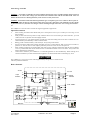
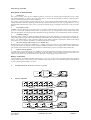
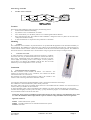
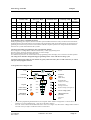
COMPACT Sinewave Inverter with integrated Battery Charger and AC Transfer Switch OPERATION & INSTALLATION MANUAL MODELS: SSC-12-1K3 SSC-24-2K3 SSC-48-3K5 TEMPERATURE SENSOR REMOTE DISPLAY SOLAR CHARGE REGULATOR SSC- TS-01 SSC- REM-01 SSC-xx-xxxS Serial No: _____________________ Model No: ______________________ SOLAR ENERGY AUSTRALIA PTY LTD ACN 081 639 938 SYDNEY. 4 BEAUMONT RD MT KURING-GAI NSW 2080 TEL (02) 9457 2277 FAX (02) 9457 2255 MELB. 1/15NICOLE CLOSE BAYSWATER NTH VIC 3153 TEL (03) 9761 5877 FAX (03) 97617789 EMAIL [email protected] WEB SITE www.solaraustralia.com.au Solar Energy Australia Compact CONTENTS GENERAL INFORMATION 3 WARRANTY 4 INTRODUCTION Basic Schematic Main Functions Battery Connections 5 6 6 INSTALLATION 7 OPERATION 9 CHARGER INFORMATION 12 POWER SHARING 13 STATE OF CHARGE MONITOR 14 MULTIFUNCTION CONTACT 14 REMOTE DISPLAY 14 PROGRAMMING CHARGING VOLTAGES 15 PROGRAMMING AUX CONTACTS 19 DISABLING FUNCTIONS 20 MAINTENANCE 20 SPECIFICATIONS 21 TRUE SINEWAVE OUTPUT VERY LOW TOTAL HARMONIC DISTORTION (THD) EXTREMELY HIGH EFFICIENCY BATTERY SAVING STANDBY CIRCUIT BUILT IN HIGH CAPACITY BATTERY CHARGER FAST ACTING AC SYNCHRONISED TRANSFER SWITCH OVERLOAD PROTECTED POWER FACTOR CORRECTION User Manual SSC-1601A COMPACT Rev 0803 Page 2 Solar Energy Australia Compact GENERAL INFORMATION Operating instructions This manual is a part of the delivery package of every COMPACT inverter-charger. It serves as guidelines for safe and efficient operation of COMPACT. The instructions are only valid for use with the following models and accessories. • COMPACT SSC-12-1K3 • COMPACT SSC-24-2K3 • COMPACT SSC-48-3K5 • COMPACT SSC-XX-XXX-S • Temperature sensor SSC-TS-01 • Remote Display SSC-REM-01 Any personnel who installs a COMPACT and/or works with it must be fully familiar with the contents of this manual and must follow exactly all the warnings and safety instructions. Installation of, or any work on the COMPACT must be carried out by a qualified and trained personnel. Installation and application must comply with the respective local installations codes and safety regulations. Quality and Warranty During production and assembling, all COMPACT Inverter/Chargers go through many testing procedures. Every COMPACT has its own serial number, which helps to refer back to its original data in the event of controls or repairs. That is why you should never remove the identification plate showing the serial number and must ensure you return your warranty card as soon as possible. The warranty period for your COMPACT is 2 Years. User Manual SSC-1601A COMPACT Rev 0803 Page 3 Solar Energy Australia Compact IMPORTANT: YOU MUST REGISTER YOUR WARRANTY SOLAR ENERGY AUSTRALIA WARRANTY Terms and Conditions Solar Energy Australia considers reliability of your power system/inverter as absolutely critical. We would rather avoid any potential inconvenience by being proactive. Many external influences can effect the reliability of an inverter, none of which are under the control of Solar Energy Australia. For these reasons we request that you register your warranty within 60 days of purchase. Warranties which are not registered receive a 6 month warranty. These terms and conditions do not exclude your rights under the statutory or implied warranty within your state or territory. Solar Energy Australia warrant this product against defects in material or workmanship, to the original purchaser only for an initial period of 6 months from date of purchase, when in normal use and service. The warranty period will be extended to a total of two (2) years when you register your warranty within 60 days of purchase (max. 3 years after date of manufacture). No warranty will be provided on units which have not been paid for in full. This warranty does not extend to products which have been opened, altered or repaired by persons other than authorised by Solar Energy Australia or to products which become defective due to acts of God, fire, sabotage, vandalism, contaminated fluids, negligence or failure to operate, house and maintain the product in accordance with instructions provided in this manual. It is extremely important that all installation and operating instructions contained within this manual are strictly adhered to. Failure to do so will void your warranty. Units which are to be installed/used within 1km of the coast must have the marine version of our product. Corrosion caused by failure to purchase the appropriate marine model will void warranty. Solar Energy Australia will use the information you supply to carry out a system check, to attempt to avoid any problems before they occur. Solar Energy Australia will repair or replace the defective product in accordance with its best judgement. For service under warranty, the buyer or installer must contact Solar Energy Australia to obtain appropriate paper work and shipping instructions before returning the unit. To make a warranty claim you must produce proof of purchase when returning the unit. Units returned without prior authorisation or warranty registration will be delayed. The buyer will pay all charges incurred in returning the product to the factory including, installers time. Solar Energy Australia will pay return freight charges, if the product is found to be defective, within the terms of the warranty. Repair or replacement of any unit does not extend the original warranty terms in any way. This warranty does not cover repairs made necessary due to the product coming in contact with dirt, abrasives, moisture, rust, corrosion, varnish or other similar, insufficient system maintenance, failure due to poor quality or poor condition batteries, failure to use the appropriate AC transfer switch or wiring carried out by inappropriately qualified personnel. Solar Energy Australia will in no way be held responsible for any losses incurred due to the malfunctioning or failure of a product. Suitably qualified personnel must carry out all AC & DC permanent wiring . Failure to do so will void warranty. To register your warranty you must do the following: Return your completed warranty registration card within 60 days of purchase. Fixed installations must provide a picture of the installation from a distance of 1 metre, household installations must supply a second picture showing the structure housing the inverter. Circuit diagram of installation. This can be obtained from your installer. If the above items are not received, they may be requested before work can commence on any faulty units. Solar Energy Australia is here to help. These measures are put in place to ensure you have years of trouble free service from your Solar Energy Australia inverter. If you have any questions about this warranty please do not hesitate to contact us. PLEASE COMPLETE AND RETURN YOUR WARRANTY CARD User Manual SSC-1601A COMPACT Rev 0803 Page 4 Solar Energy Australia Compact Caution: Even when a COMPACT has been completely disconnected, there can still be deadly voltages present at the OUTPUT. To remove these voltages you must switch the COMPACT ON with the ON/OFF switch. After one minute the electronics are discharged and any work can now be safely carried out. Caution: In normal use lead-acid and lead-gel batteries give out explosive gases. Never smoke or allow a spark or flame in the vicinity of batteries. The batteries must always be stored or placed in a well ventilated area, they should be placed in such a way that there is no danger of short circuiting through carelessness. Never charge frozen batteries. The COMPACT is not to be used or sold for life support equipment or applications. Special Precautions • • • • • • • While working on batteries there should always be a second person close to you or within your voice range, in case help is needed. Plenty of fresh water and soap must be ready at hand so that in case of acid coming in contact with skin , eyes and clothes, the areas in question can be thoroughly washed. If acid enters the eyes, you must thoroughly wash the eyes with cold running water for at least 15 minutes. It is recommended that you immediately consult a medical doctor. Baking powder neutralizes battery acid electrolyte. Always keep some at hand. Special care must be taken when working with metal tools near or on the batteries. With tools such as screwdrivers, spanners etc. short-circuits can result. Sparks produced by the short-circuit can cause an explosion. When working on batteries all personal metal items such as rings, necklaces and bracelets must be removed. Batteries are so powerful that short-circuit with these items can melt them and thus cause severe burns. Always follow the battery manufacturers instructions. Under certain conditions your COMPACT or a connected generator can start automatically. While working on an electrical installation you must ensure that these appliances are disconnected before commencing any work. INTRODUCTION The COMPACT is a sine wave inverter with integrated battery charger and AC transfer switch. with many additional functions. Basic schematic AC IN 1uF L Input 100nF PE 230Vac 10nF PE Output N 10nF 4x2,7MΩ Filter CT35 Temp. Sensor 1uF Microprocessor, Control, Adjustment SOLAR Display Solarmodule Max. 6m 230Vac Inverter Charger 150A 1uF N AUX. CONT. Battery BATTERY AC OUT L Remote Remotecontrol control Temp. 6p RJ11 8p Remote control COMPACT RCC-01 AC IN Max. 40m CHARGER INVERTER - CHARGER TRANSFER AC OUT EQUALIZE Program ALARM (Select) Over Temp. Overload Battery Low/High Contact active Contact manual AUXILIARY User Manual SSC-1601A COMPACT Rev 0803 (Program) CONTACT A % 160 130 INVERTER RESET SOLAR CHARGE 70 100 60 80 50 60 40 40 30 20 20 10 10 Ch arg er 5 Inv ert er OFF (Change ON/ OFFstatus) Page 5 Solar Energy Australia Compact Description of main functions 1. The Inverter The sinewave-inverter section of your COMPACT generates a sinewave AC voltage with an exceptionally precise voltage and stabilized frequency. In order to start large electric motors , the user has the possibility to employ a short-start-power which is 3-times the nominal power of the COMPACT. The inverter is protected against overload and short-circuit. A power-stage with the latest MOS-FET power transistors, a toroidal transformer, and a fast regulating system make-up a robust and reliable inverter with very high efficiency. A 1-20 Watt adjustable load detection system serves to provide the smallest energy consumption and ensures a long life for the battery. 2. The Transfer system COMPACT can be connected to an AC input source. For example a stand-by motor generator or the AC grid, such as shore power or a caravan park. With the transfer system, on one side you have AC voltage which is used to run the load, on the other side the batteries are being charged. The distribution of energy between the AC loads and battery charger is automatic. 3. The Battery charger The built-in battery charger is capable of charging the batteries quickly and completely. A microprocessor controlled, 3 to 4 Step charging process ensures the optimum charging of the batteries. The desired charging current can be set continuously from 0 – 55A (SSC-48-3K5 0 - 50A). The battery charger can be used for lead-acid or gel batteries. Thanks to the floating charge ability of your Compact, the batteries can remain continuously connected. 4. The solar charge regulator (SSC-xx-xxx-s models only) With the built-in solar regulator, the COMPACT is a complete solar-power-center. In a solar installation this regulator ensures that the batteries are charged correctly. With the COMPACT, batteries can be charged with a generator and with the solar modules at the same time. The charging of batteries with both energy sources is carried out fully automatically. 5. Remote control (optional) A remote display can be connected to your COMPACT. All operating elements and displays with the exception of the load detection level adjustment are available on the remote control. The remote control is supplied with a 20m long cable. This cable can be up to 40m long. On the remote control output power and charging current are also shown. Battery connections Lead-acid batteries are normally available in blocks of 2V, 6V or 12V . In most cases, to generate the necessary operating voltage and the capacity of the batteries for the COMPACT many batteries have to be connected together in parallel and or in series. Following three examples are shown: 1. Parallel Connection: Maximum 2 batteries in parallel. 12V 2. 12V 12V Series Connection 2V 2V 2V 2V 2V 2V 2V 2V 2V 2V 2V 2V 12V 24V 2V 2V 12V User Manual SSC-1601A 2V 12V 2V 2V 12V 2V 12V COMPACT Rev 0803 48V Page 6 Solar Energy Australia 3. Compact Parallel- Series Connection: 12V 12V 12V 12V 24V INSTALLATION Location The location of the COMPACT must be chosen by the following criteria: • Protection from unauthorized handling. • Dry dust free room, no condensation, no rodents. • Never install directly over the battery and never in a cabinet together with the batteries. • Keep ventilation holes free. The ventilation of the COMPACT is designed in such a way that it will work most efficiently when mounted vertically. • In mobile installation it is important to keep vibrations to a minimum. Mounting 1. Compact The COMPACT can be installed in any desired location. It is preferred that the appliance be wall mounted with battery cables downwards. The COMPACT is fixed on the wall with four screws through the four holes (dia. 5.5mm) which are accessible from the outside. In motor vehicles, the COMPACT must be fixed on vibration reducing mounts. The COMPACT must not be fixed on a combustible wall, as the back of the casing can get hot and reach up to 80 degree Celsius. 2. Protection cover IP23 To reduce the chance of foreign objects entering the Compact or condensation from a steel roof, you should use the IP23 cover (Part No SSC-IP23-01) this is easily installed after fixing the COMPACT to the wall. To do this, release slightly the mounting screws of the Compact, it’s then possible to pass the IP 23 cover between the COMPACT and the wall. The cover must touch the top screws. Retighten the 4 screws. It’s ready. Connection 1. General instructions on connecting The cable connection on the terminals AC INPUT / AC OUTPUT / 15A 230VAC are carried out with a No 1 screwdriver, the connection on the SOLAR terminal with a No 2 screwdriver. The conductor cross section on the terminals AC INPUT / AC OUTPUT / 15A 230VAC of the connecting cable must be minimum. 2.5mm2 . All connecting cables and also the mounted battery cables , must be fixed with strain relief clamps. The COMPACT is delivered with battery cables already connected. The battery cables must never be extended. If the extension is unavoidable then the conductor cross section must be increased, contact your installer for this calculation. To protect the battery cable, a fuse corresponding to the conductor cross section must be fixed directly on to the battery. All cables must be tightly screwed in place. For safety, a yearly maintenance program is recommended. In mobile installations, maintenance must be carried out more often. Connections must be done by qualified personnel. Material such as cable, connectors and distribution boxes, fuses etc. used in the installation must comply with the respective valid low-voltage installation rules and regulations Applicable Standards. AS4509. Remote Home Power systems AS4086. Secondary batteries for use with Stand Alone Power systems AS 3010.1 Generators User Manual SSC-1601A COMPACT Rev 0803 Page 7 Solar Energy Australia Compact 2. Protection cover for the terminals connections (supplied standard) It is possible to provide gland protection for AC terminations by using the cover supplied. This allows AC cabling to pass through a cable gland before connecting to the Compact, this cover is supplied with cable glands. (see picture) Connections M A L Do not open before disconnectin battery N Caution Check battery polarity (+/-) before connecting! A wrong connection could damage the system. BATTERY 15 sfe elay SOLAR Remote control B C Auxiliary Contact 15A-250Vac Eq ua liz e D AC Input N PE L Temp. E F G H Typ: N°: ssc-xx-x 22-32 Vdc Vbat: Pnom: 2000 VA Uin: 150 - 250 Vac Uout: 230 V/50 Hz I Solar: 30A max. I Charge: 70A J AC Output N PE L K Connections / Front Side A B C D E F G H Battery +/SOLAR +/Remote control Equalize Transfer delay Temp. Aux. Contact AC Input J K L ID Plate AC Output Caution M N Don’t … 15A Protection User Manual SSC-1601A Battery cables Connections for Solar modules Connecting terminal for Remote Control SSC-REM-01 Slide switch for equalization of the Battery Slide switch for Transfer Delay Connecting terminal for Temperature sensor SSC-TS-01 Connecting terminal for Auxiliary Contact Connecting terminal for AC-input. Located directly above this terminal is the automatic safety cut-out for this terminal Identification plate with Technical data and Serial number Connecting terminal for AC-output Caution: Check Polarity (+/-) before connecting to battery. Polarity reversal can damage the COMPACT. Do not open without disconnecting all terminals 15A Protection switch for the Transfer system COMPACT Rev 0803 Page 8 Solar Energy Australia Compact Cabling/wiring When making connections to the Compact you must ensure that all connections are carried out in a clean and correct manner and under no circumstances that a cable is connected to a wrong terminal. Connecting the COMPACT must be carried out in the following order. (a) Pre-installation settings Before you start with the wiring of the COMPACT you must set the type of battery. If sealed-gel batteries are used then you must set the small slide-switch ”Equalize“ which is on the front with the connecting terminals, to OFF position. In case of normal lead-acid batteries, these can handle a higher equalizing charge, the same slide switch can be set to the ON position. If in doubt leave the setting in the OFF position. (b) Connection to battery Prepare the batteries for connection. Prepare battery cables, if necessary press on cable tabs/shoes. Connect the red cable to the Battery positive fuse/circuit breaker and the black cable to battery Minus(-) Take care when connecting the second cable to the battery, as a spark is produced, this is caused for a short time due to high current flowing in the COMPACT to charge the capacitors. This is another reason to install a battery fuse/circuit breaker. For this reason follow strictly the safety measures described in this manual. DO NOT INSERT THE BATTERY FUSE AT THIS STAGE. (c) Connection to the AC OUTPUT The AC output must be connected to the screw terminal AC OUTPUT. For this, use a 3-core cable with a conductor cross section of 2,5mm2. Connections are marked as follows “N“= Neutral, “PE“= Earth, “L“= Live or Active. Caution: High voltage can be at the AC output, ensure the Compact is not connected when making AC connections (d) Connection to the AC INPUT The AC input supply from the electricity grid or from a generator must be connected to the screw terminals marked AC INPUT. For this use a 3-core cable with a conductor cross section of 2,5mm2. Connections are marked as follows “N“ =Neutral, “PE“= Earth, “L“ = Live/ Active. (e) Connect the Solarmodules: SOLAR +/- (Only for solar option) Solar modules are connected on these terminals. Under no circumstances should any other energy source i.e. wind generator be connected to these terminals. Depending on the power of the modules, the cable cross section should be 2.5 up to 6mm2 . Before connecting it is necessary to check with a Voltmeter that the voltage of the Module meets the following values: SSC-12-1K3S 17-25V /30A, SSC-24-2K3S 34-45V /30A, SSC-48-3K5S 68-90V /20A. (f) Connection to Auxiliary Contact On these three terminals is a potential free change-over contact capable of switching a maximum current and voltage of 16A/250Vac. The “Contact active” LED shows the status of these contacts, when the LED is ON, the contacts are active. The schematic view of the connections on the front of the Compact, shows the contacts in the non active state. (g) Connection to Remote display The Remote Display SSC-REM-01 is connected in the terminal marked “Remote control“ with a RJ11/8 connector. The Remote Control can be plugged IN at any time. Push in the connector, without forcing it, until you hear the „click“, now the connector is locked in place. The same applies to the plug at the Remote Display end. The length of the cable for the Remote Display should not exceed 40m, is comes standard with 20m cable. (h) Connection to Temperature Sensor (Optional.) The Temperature sensor SSC-TS-01 is connected to the terminal marked “Temp“ with a RJ11/6 connector. The Temperature Sensor can be plugged IN at any time. Push in the connector without forcing it, until you hear a click, now the connector is locked in place. The Temperature Sensor should be glued or taped to the wall of the battery or near it. The Temperature Sensor cable must not be tied together with the battery cables or laid in a cable bundle. OPERATING You can now apply power to your compact by inserting the battery fuse: Caution: this will generate a spark. Check if the “OFF” LED is lit. If it is not lit, press quickly the “ON/OFF” switch, now “OFF” should be lit. On connecting the battery the COMPACT needs 1 – 2 Minutes to calculate the actual State of Charge of the battery. During this time the battery State of Charge is shown as 100% charged. (LED 14,15,16 &17 lit). If the LED marked “Battery Low/High” is lit, the battery charge is too low. If the LED marked “Battery Low/High” is blinking, the battery charge is too high. Caution: With a wrong battery voltage the COMPACT can be destroyed. ( For example: connecting a SSC-12-1K3 to a 48V Battery). If the COMPACT has been connected with reverse battery polarity, it must be returned to Solar Energy Australia for repair. User Manual SSC-1601A COMPACT Rev 0803 Page 9 Solar Energy Australia Compact Display and operating control elements INPUT LIMIT CHARGER 16A TRANSFER 70A 0 STANDBY 20w 230V 0 OFF 150V AC OUT AC IN CHARGER INVERTER RESET ALARM Lock (select) SOLAR CHARGE EQUALIZE 14 Over Temp Program 15 Overload Contact Active Batt Low / High 16 Contact Manual OFF 17 18 AUX. CONTACT (Program) ON / OFF (Change status) (a) Light Emitting Diodes: (LED’s) LED Marking LED ON AC IN Incoming AC voltage is within the required parameters Incoming AC voltage is NOT within the required paand is present at the AC IN input. rameters.. Battery Charger is working The input voltage is out value (voltage or frequency) CHARGER LED blinks SOLAR CHARGE Optional Solar modules are delivering energy Program Contact active You have enetered the Program mode for the Aux. Contact Auxiliary Contact is activated Contact manual Aux. Cont. manually activated AC OUT Transfer system is active. In- coming voltage is being sent directly to AC OUT outlet There is voltage at the AC OUT outlet The Inverter is in Standby-Mode INVERTER Inverter is working Over Temp. The COMPACT has shutdown because of overheating. Compact will automatically restart. The COMPACT has shutdown because of overload or short-circuit. Compact may automatically restart. Battery voltage is too low Battery voltage is too high Overload Batt. Low/High Forced -Inverter Mode OFF COMPACT is turned off. It can only be turned back on manually. Battery Charger and or Solar Charge Regulator are doing an equalization cycle Approx state of charge of Battery CURRENT MONITOR Displays the value of the output power in % of max continuous power (in Inverter Mode) and the charge current in Amps. (in Charger Mode) In this mode the 200% LED indicate that power sharing is in use. 14 15–18 User Manual SSC-1601A COMPACT is for the time being turned off. Turning it back on will follow automatically! LED 15 – Absorption time is running COMPACT Rev 0803 Page 10 Solar Energy Australia (b) (c) Compact Push buttons ON/OFF Turning the COMPACT on and off (Help Button for Programming) RESET Press to turn OFF Alarm Signal. (Help Button for Programming) Aux. Contact Manually activates the Auxiliary contact. (Help Button for Programming) Turning Knobs CHARGER Adjustment for max. Charging Current (Not for Solar charge regulator) TRANSFER Adjustment for Transfer Voltage Threshold(TRANSFER – INVERTER) STANDBY Adjustment for “Standby“ system INPUT LIMIT Must be adjusted to the maximal available current of your AC INPUT supply (see separate chapter for further information) The Inverter The Inverter section of the COMPACT produces a high quality Sinewave output, the quality of this output is compatible with any appliance. Thanks to the generous dimensioning of the COMPACT, you can operate appliances requiring higher power than the nominal power of the COMPACT for a short time. The COMPACT provide up to 3-times the nominal power to start motors etc. The Inverter mode is displayed through LED marked “Inverter” If the Inverter Mode is disabled (see elsewhere in this manual) this LED will blink. If the LED is lit, the Inverter is in operation and you have 230Vac at output AC OUT. The actual power consumption of the AC load is displayed on the power monitor and on the remote display. (a) Load detection system “Standby“ In order to avoid unnecessary discharge of the battery, the inverter switches OFF automatically if no AC power is being used. The Compact switches ON automatically again if an AC load is switched ON. The AC Out LED blinks if the inverter is in Standby-Mode. The switching-ON threshold can be adjusted with the “STANDBY” adjustment dial. Adjusting the switching-on level is done using a small screwdriver as follows: Switch off all AC loads; turn the “Standby” dial to the right until the AC Out is blinking, switch on the smallest AC load (i.e. Mobile phone charger); turn the “Standby” dial slowly to the left until the AC Out LED is lit. If the Standby- Mode is not wanted, turn the “Standby” dial to the left, to the OFF position, this will keep the Compact running continuously, but will also discharge your batteries quicker. (b) Overload If the Compact is overloaded for too long or too heavily, it switches off. The “Overload“ LED is lit and the “OFF“ LED will blink. After approximately 10 seconds the Inverter switches on automatically. If the Inverter is overloaded four times in quick succession, then it no longer switches back on automatically, if this occurs contact your Solar Energy Australia representative immediately. The OFF LED remains lit. Press the “ON/OFF“ push button in order to switch the Inverter back ON. (c) Overheating(Over Temp) If the Inverter has been overloaded for a long time or it has been working in a high ambient temperature, it will switch OFF. The “Over Temp“ LED is lit and the “OFF“ LED blinks. After cooling down, the inverter switches back on automatically. One minute before the inverter switches off due to high temperature a buzzer will be heard. If the Auxiliary Contact has been programmed for “Over Temp” then the contact will be active when the buzzer sounds. This could be used for example to start an emergency back up generator, creating a no break energy supply. (d) Battery Condition Deep discharging of batteries leads to high losses in capacity and early aging. That is why the Compact will constantly monitor the battery condition. When battery voltage gets too low the Compact switches OFF. The “Batt Low/High” LED is lit and the “OFF“ LED blinks. When the battery voltage returns to 12.1V / 24.2V / 48.4V, the Inverter switches ON automatically. One minute before the Inverter switches OFF due to low voltage, a buzzer will be heard If the Auxiliary Contact has been programmed for “Low Battery” then the contact will be active when the buzzer sounds. This could be used for example to start a warning system, to shut down critical equipment such as computers. The low voltage is set to 11.8V / 23.6V / 47.2V. These settings are standard for most batteries. The voltage levels are maintained by the built-in Battery-Management-System of the COMPACT which looks at the load and battery condition and adjusts to suit. This setting is comparable with the levels of 10.8V/ 21.6V / 43.2, which are given for most batteries on nominal load. All voltage levels can be adjusted to suit your system. To adjust these levels see the instructions under the section on Programming. Check your battery supplier or system installer for the suggested values for your batteries. User Manual SSC-1601A COMPACT Rev 0803 Page 11 Solar Energy Australia Compact [V/cell] [A] 2.50 Equalization 70 2.33 Absorption 60 Float charge Charging current 2.17 A Charg. Phase / adjust. current 40 B Equalization time C Absorption time 2.00 D Float charging phase 20 A t B C D The Battery charger (a) Charging Cycle The fully automatic COMPACT Battery Charger is adjusted at the factory so that most lead-acid and lead-gel batteries can be charged to the maximum. As soon as the minimum AC voltage (as set with the “Transfer” adjustment dial) is available at the AC input (“AC IN” LED is lit), the Battery Charger is switched on automatically (“CHARGER” LED is lit). The battery is automatically charged to match the pre adjusted voltage levels and charge current. Thanks to the Compacts sophisticated and intelligent Floating Charge System, the batteries can be left in charge mode for unlimited time. During the charging cycle, the AC loads are continually supplied with power from the incoming AC voltage source. ( “AC OUT” LED is lit). The charger functions are shown in the following diagram: (b) Equalization charging: Equalization charge is a higher voltage applied to the batteries for a specified period of time. Equalization mode should never be used when using Gel-Batteries Before you program the COMPACT for Equalization-charge you must confirm with your supplier that the batteries are suitable for this process. Equalization is recommended for lead-acid batteries in order to mix the electrolyte fluid and to clean the lead plates of the batteries. If the COMPACT is operating with a lead-acid battery which is suitable for equalization, the slide switch “Equalize“ which is on the cable connection side, must be placed in the ON position. In this setting, at every 25 charge cycles an equalization cycle will be carried out for 2 hours (factory setting). During such a charge cycle the “Equalize” LED is lit. During a Charge cycle, equalization can be started independent of the actual programming. For this the slide switch must be slid from “OFF” to the “ON” position. The Equalize LED will light up. If the periodic equalization is not required, slide switch must be slid back to the „OFF“ position after the completion of the manual cycle. (c ) Absorption Charge Your Compact will provide a constant charge current until the absorption voltage is reached, note that this is the peak voltage and may not read accurately with a meter due to the ripple current. LED 15 will flash to indicate the absorption phase is running. As the battery state of charge increases, the charge current will be reduced and the battery voltage will continue to rise. CAUTION: During the equalization process, the batteries will produce a lot more gas. DANGER OF AN EXPLOSION !! User Manual SSC-1601A COMPACT Rev 0803 Page 12 Solar Energy Australia Compact Input current repartition (Power sharing) To manage the power available on the AC INPUT the COMPACT is equipped with a system usually called “Power sharing” or INPUT power distribution. With this feature it is possible to limit the AC INPUT current assigned to the charger. The more current used by the AC load, the less power is given to the charger. Priority for the AC Loads. When power sharing is used the red 200% LED on the power monitor is lit to show that the battery charging is being limited Generator Power 500W 900W 1500W 2000W 3000W Current (230V) 2A 4A 6,5A 8,5A 13A Set the INPUT LIMIT The current available to the COMPACT depends on the source of the AC input supply, i.e. motor generator, limited grid supply in a caravan park or shore power. The value of the “INPUT LIMIT” adjustment dial must be lower or equal to the current available from the AC Input source. For example if you have a generator of 2kW you must adjust the “Input Limit” to approximately 8.5A. To calculate this, divide the nominal power of the AC input source (2000W) by the voltage (230V). If the circuit breaker before the COMPACT is lower than this value, then you must set the “Input Limit” to the value of the circuit breaker. Charging current The maximum charging current for the battery can be adjusted using the “CHARGER” adjustment dial. The charging current should be set to approximately 10% of the battery capacity (at C10). This means that the charging current for a battery with 300Ah should be approx 30A. The charging current is displayed on the “CURRENT MONITOR” on the front panel and on the Remote Display. Battery condition The built in microprocessor features a specially developed algorithm (formulae) which calculates the actual state of charge ( SOC) of the battery and displays it on LED 15-18. The Equalize LED is lit when the system is performing an equalization charge. The SOC displayed should be used as a guide only, for batteries which are not sealed, use a hydrometer to determine the exact SOC. For Safety reasons, you must get the recommended charge voltage and charge current from your battery supplier. The voltage levels and charge characteristics can be changed through “Programming”. The correct charging levels are critical for safe functioning and long life of the battery. 14 Equalization cycle 15 Battery 75 – 100% 16 Battery 50 – 75% 17 Battery 25 – 50% 18 Battery 0 – 25% The Transfer system When an AC voltage is present at the AC IN of the COMPACT, the “AC IN” LED is lit. When this voltage matches the lowest adjusted value set by the “TRANSFER” dial, and the frequency is between 44Hz and 65Hz, then this power is transferred directly to the AC load and the battery charger section of the Compact. The “TRANSFER” LED is lit to indicate this has happened. The inverter is then switched off and the battery charger switched on. This process is automatic and should not be noticed by the load, at worst a slight flicker may be seen in lights. The maximum current of the Transfer switch is 15A. That means through this system, AC loads of up to a maximum 3500 Watts can be operated. When the Battery Charger is working, part of this power is used for the charging according to the power sharing settings. The Transfer system is protected against overload with an automatic safety fuse on the AC Input side of the COMPACT. If the system has been overloaded the button/pin of the fuse will pop-out. To put the automatic safety system back in to operating you must push this pin back in. User Manual SSC-1601A COMPACT Rev 0803 Page 13 Solar Energy Australia Compact Note: In the Inverter operation, the COMPACT generates a True Sineusoidal and quartz stabilized output voltage. However, when the COMPACT is transferring power supplied from the a grid or a generator the voltage and quality of the power running the AC load will be the same as that coming from the grid or generator. The Compact cannot modify the incoming voltage. Setting the transfer voltage threshold The voltage threshold of the transfer can be adjusted between 150 to 230V with the “Transfer” adjustment dial . This value is set at the factory with a value of 200V. The majority of appliances can work on this voltage. When the Input voltages reaches the selected value on the adjustment dial, and the frequency is between 44Hz and 65Hz,. then the inverter switches off and the AC INPUT goes directly ton the AC OUTPUT. When the voltage INPUT is 20V less than the value set, the transfer of power is stopped and the OUTPUT is switched back to the inverter. Do not use the adjustment dial “TRANSFER” to adjust the AC OUTPOUT voltage! This is only a voltage threshold level to enable or disable the transfer. FAST (UPS)- MODE for the Transfer Switch The quick and almost break free Transfer mode is programmed with a slide switch „“Transfer Delay“ OFF”, which is on the front side with the( cable connections side) of the Compact. The aim of the COMPACT is to supply the AC loads with almost break-free AC power. When the incoming voltage “AC IN“ no longer matches values which have been set with the “Transfer” adjustment dial, the Compact switches back to Inverter. The transfer is carried out in around 0.02 seconds. This quick transfer ensures that the a break-free function for most AC loads is achieved. If AC voltage is restored at the AC Input which is within the set parameters, the transfer of power will resume, the inverter is stopped and battery charging will recommence. Delayed mode of the Transfer System The delayed mode of the transfer system Transfer Delay ON is programmed with the slide switch on front with the cable connections. The COMPACT provides an almost break-free alternating voltage for the AC loads. A quick transfer switch is not always sensible nor is it always desired. For example, when the AC load is being operated by a small standby back-up generator. An overload of a short duration on such a generator, i.e. start of a vacuum cleaner etc., has the effect of decreasing the voltage for a short time. As in such cases the transfer to the Inverter is not desirable, the transfer system can be programmed with a delay. When the slide switch (Transfer delay) is in the „On“ position, the transfer to the inverter takes place with a delay of 5 seconds. If the voltage falls below 100Vac, the transfer takes place without delay! The transfer switching to the Inverter takes place without any break. The Solar charge regulator (option) A COMPACT model is available with an inbuilt Solar Charge Regulator. To charge the batteries, Solar modules can be connected to the screw terminal SOLAR +/-. The in-built regulator is a Shunt regulator with a maximum input current of 30A for SSC-12-1k3 and SSC-24-2K3, 20A for SSC-48-3K5. The operating voltage of Solar modules to be connected must match the actual operating voltage of the COMPACT and never exceed the max. rated value. Under no circumstances should any other charging sources such as a wind-generator be connected at the input of the Solar Charge Regulator. The Solar Charge Regulator works automatically and is always in operation. As soon as the energy is delivered from the Solar Charge Regulator, the “SOLAR CHARGE” LED is lit and the batteries are being charged. The Solar Charge Regulator works even when the Battery Charger is functioning. The method of operation is a 3 or 4 step charging process, the same as the battery charger. The function is described in the section on “Battery Charging”. The programming and the adjustments are carried out in accordance with the same conditions. Check with your battery supplier which adjustments must be carried out for your battery. User Manual SSC-1601A COMPACT Rev 0803 Page 14 Solar Energy Australia Compact The Multifunctional Contact In the COMPACT there is a built-in programmable power relay. The potential-free change-over contact (n/o – n/c) of this power relay is connected to the screw terminals “ AUX CONTACT”. Maximum Contact load: -230Vac /16Amp-30Vdc/1A With the Push Button “AUXILIARY CONTACT“ the contact can be manually switched on or off independent of programming and the operating situation. The “Contact active” LED shows the status of the contact. The drawing on the screw terminal “AUX CONTACT” shows the inactive position, “Contact active” LED off. The switching on and off of this contact can be freely programmed for each operating situation of the COMPACT that is indicated with a LED. There is no limitation to its applications. An example and the setting of this contact are explained elsewhere in this manual. In the factory we program this output to be active when one of these situations are detected: * Over temperature LED lit * Overload LED lit * Over or under voltage of batteries LED lit or blinks * Compact is turned OFF manually or with a fault (OFF LED lit) * If the COMPACT is turned off manually or has turned OFF due to a fault, the “OFF” LED will be lit. THE REMOTE DISPLAY As an option, a Remote Display can be connected to the COMPACT. All operating controls and displays except for level adjustments are available on the Remote Display. The Remote Control is supplied with a 20m long cable. It can be lengthened up to a maximum of 40m. The Remote Display is suitable for surface mounting on the wall or on to a switch board. It is fixed with 4 screws. The COMPACT can also be programmed with the Remote Control. The Programming is described in the section “Programming“. User Manual SSC-1601A COMPACT Rev 0803 Page 15 Solar Energy Australia Compact ON/OFF ! -batt ! COMPACT Remote display 1234 Dry contact only Remote control The output power and the charging currents are displayed on the Remote Control. 60V/0,5A max. The Control Input is connected in parallel to the ON/OFF- push button. The COMPACT can be switched on or off through this input with an impulse button or an impulse contact. Order Number for Remote Control: SSC- REM-01 Dimensions: H x W x D / 111.5 x 136.5 x 25mm Caution: No external voltage should be connected to this Input Control. The Temperature sensor (Optional) Charging voltages of lead-acid batteries can change depending on temperature. To correct the operating voltages according to the actual temperatures, a temperature sensor can be connected to the COMPACT. The compensation through the sensor is –3mV/°C/Cell. Order Number: SSC-TS-01 Dimensions: H x W x D / 58 x 51.5 x 22mm PROGRAMMING Factory settings The COMPACT is delivered with the following default settings: (a) Battery voltages Low voltage Float Charge Absorption Voltage ( at completion) Equalization Absorption Time: 11.6V / 23.2V / 46.4V 13.5V / 27.0V / 54.0V 14.4V / 28.8V / 57.6V 15.3V / 30.6V / 61.2V 2 Hours (b) Auxiliary contact Active in case of fault or manual turn off with the ”OverTemp”, “Overload”, “Batt Low/High” and “OFF” LED Resetting Factory Settings When the COMPACT is to be connected to a battery or after an interruption (RESET), it will default back to the factory settings.. In order to get to these settings during operation you must press the three Push Buttons “On/Off”, “Reset Alarm” & “Aux Contact” simultaneously for a minimum of 2 seconds Charging Voltages and absorption time The voltage levels (low voltage, float charge, end of charge (absorption) and equalization ) and the duration of the absorption charge can all be adjusted. The range of these settings are shown in the table below: The bold print shows the factory settings. User Manual SSC-1601A COMPACT Rev 0803 Page 16 Solar Energy Australia Compact Low voltage “On/Off” LED LED 12V 24V 48V Float Charge “Batt Low / High LED 12V 24V 48V Absorption “Overload” LED Equalization “Overtemp” LED 14 12.0 24.0 48.0 13.7 27.4 54.8 16.2 32.4 64.8 16.2 32.4 64.8 4h 15 11.8 23.6 47.2 13.6 27.2 54.4 15.6 31.2 62.4 15.9 31.8 63.6 3h 16 11.6 23.2 46.4 13.5 27.0 54.0 15.0 30.0 60.0 15.6 31.2 62.4 2h 17 11.4 22.8 45.6 13.4 26.8 53.6 14.4 28.8 57.6 15.3 30.6 61.2 1h 18 11.2 22.4 44.8 13.3 26.6 53.2 14.2 28.4 56.8 15.0 30.0 60.0 0 – 1Min. 12V 24V 48V 12V 24V 48V Absorption Time All LED’s Programming Voltages and timing threshold. When programming your Compact, switches and LED’s perform different functions as they do when in the normal mode, the diagrams below shows the function of each when in the programming mode, the normal meanings are in brackets. Programming can be done at any time and will not interfere with the Compacts operation. All voltages mentioned should be halved for 12v systems and doubled for 48v systems. All voltage and Timing programming is done in the following manner: Press “Program” & “Change Status” buttons simultaneously to enter programming mode Press the “Select” button to choose the parameter you want to change Press “Change Status” button to change the values. If no buttons are pressed for 10 seconds whilst in the programming mode, the display will revert back to normal operation. The voltage levels and times changed through programming will be active with the next charge cycle! CAUTION Voltage levels which are not suitable can greatly reduce the battery life or could even destroy it ! Check with your battery supplier if unsure. To Programm Low Voltage Cut Out AC OUT AC IN CHARGER INVERTER SELECT (Reset Alarm) SOLAR CHARGE 24.0v Set Equalisation Voltage (Over Temp) Program 23.6v Set Absorption Voltage (Overload) Contact Active 23.2v Set Float Voltage (Batt High/Low) 22.8v Set Low Voltage (OFF) Contact Manual PROGRAM (Aux Contact) 22.4v CHANGE STATUS (ON/OFF) Absorption Time * * To enter the programming mode hold down, the “Program” button and the “Change status” as shown above, for minimum 2 seconds simultaneously. ( You will see the LED’s change) Press the “Select” button until the Red LED next to “Set Low Voltage” is lit, then use the “Change Status” button to select the value you require as indicated on the 5 centre LED’s. User Manual SSC-1601A COMPACT Rev 0803 Page 17 Solar Energy Australia Compact To Program Absorption Voltage AC OUT AC IN CHARGER INVERTER SELECT (Reset Alarm) SOLAR CHARGE 32.4v 30.0v Set Equalisation Voltage (Over Temp) Program 31.2v 29.6v Set Absorption Voltage (Overload) Contact Active 29.2v 30.0v Set Float Voltage (Batt High/Low) 28.8v Set Low Voltage (OFF) Contact Manual PROGRAM (Aux Contact) 28.4v CHANGE STATUS (ON/OFF) Absorption Time * * To enter the programming mode hold down, the “Program” button and the “Change status” as shown above, for minimum 2 seconds simultaneously. Press the “Select” button until the Red LED next to “Set Absorption Voltage” is lit, then use the “Change Status” button to select the value you require as indicated on the 5 centre LED’s.. To Program Absorption Time AC OUT AC IN CHARGER INVERTER SELECT (Reset Alarm) SOLAR CHARGE 4hrs Set Equalisation Voltage (Over Temp) Program 3hrs Set Absorption Voltage (Overload) Contact Active 2hrs Set Float Voltage (Batt High/Low) 1hr Set Low Voltage (OFF) Contact Manual PROGRAM (Aux Contact) 0-1min CHANGE STATUS (ON/OFF) Absorption Time * * To enter the programming mode hold down, the “Program” button and the “Change status” as shown above, for minimum 2 seconds simultaneously. Press the “Select” button until the all 4 Red LED’s are lit, then use the “Change Status” button to select the value you require as indicated on the 5 centre LED’s. User Manual SSC-1601A COMPACT Rev 0803 Page 18 Solar Energy Australia Compact To Program Float Voltage AC OUT AC IN CHARGER INVERTER SELECT (Reset Alarm) SOLAR CHARGE 27.4v Set Equalisation Voltage (Over Temp) Program 27.2v Set Absorption Voltage (Overload) Contact Active 27.0v Set Float Voltage (Batt High/Low) 26.8v Set Low Voltage (OFF) Contact Manual PROGRAM (Aux Contact) 26.6v CHANGE STATUS (ON/OFF) Absorption Time * * To enter the programming mode hold down, the “Program” button and the “Change status” as shown above, for minimum 2 seconds simultaneously. Press the “Select” button until the Red LED next to “Set Float Voltage” is lit, then use the “Change Status” button to select the value you require as indicated on the 5 centre LED’s. To Program Equalisation Voltage AC OUT AC IN CHARGER INVERTER SELECT (Reset Alarm) SOLAR CHARGE 31.0v 32.4v Set Equalisation Voltage (Over Temp) Program 30.8v 31.8v Set Absorption Voltage (Overload) Contact Active 30.6v 31.2v Set Float Voltage (Batt High/Low) 30.4v 30.6v Set Low Voltage (OFF) Contact Manual PROGRAM (Aux Contact) 30.2v 30.0v CHANGE STATUS (ON/OFF) Absorption Time * * To enter the programming mode hold down, the “Program” button and the “Change status” as shown above, for minimum 2 seconds simultaneously. Press the “Select” button until the Red LED next to “Set Equalisation Voltage” is lit, then use the “Change Status” button to select the value you require as indicated on the 5 centre LED’s. User Manual SSC-1601A COMPACT Rev 0803 Page 19 Solar Energy Australia Compact PROGRAMMING THE AUXILLIARY CONTACT (a) Principle The Auxiliary Contact can be basically programmed for any operating situation of the COMPACT which is indicated with a LED. The programming is possible for one or more operating situations. If the contact is programmed for many situations, it is activated as soon as the COMPACT finds itself in any one of the programmed situations.. (b) The programming of the Auxiliary Contact is carried out in the following Steps: Press down the “Program” button for min. 2 seconds. The “Program” LED is lit to show the COMPACT is in program mode. A flashing LED indicates that condition has been programmed to activate the auxiliary contact. The Compact is factory programmed with “Over Temp”, “Overload”, “Battery Low High” and “Off” as the conditions which will activate the auxiliary contact. These will flash when you first enter the programming mode. Once in the programming mode use the “Select” button as per diagram below to choose the desired condition in which the contact should be activated, if the yellow “Contact Active” LED is flashing then this condition is already selected to activate the auxiliary contact. Pressing the “Change status” button will activate or deactivate this setting. If desired , push the “Select” button to choose another condition in which the contact should be activated. With the “Change status” button confirm or change the status for this condition. If during 10 seconds no buttons are pushed, then the chosen values are automatically stored and the COMPACT switches back to normal operating condition INPUT LIMIT CHARGER 16A 0 TRANSFER 70A STANDBY 20w 230V 0 150V OFF AC OUT AC IN CHARGER INVERTER SELECT SOLAR CHARGE EQUALIZE 14 Over Temp Program 15 Overload Contact Active 16 Batt Low / High Contact Manual 17 OFF 18 (Program) (c) (Change status) Example Auxiliary Contact as generator starter When in the programming of the Auxiliary Contact, the State of Charge (SOC)LED’s (LED 15-18) can be used as a condition, but you must take note of the following requirements. If you have to start an emergency back-up supply with a battery having a certain SOC, then two SOC levels must be programmed. The first (i.e. Battery 25% LED 17) for the starting or activating the Auxiliary Contact and the second (i.e. Battery 100% LED15) for stopping or deactivating the Auxiliary Contact. By programming in this way the Auxiliary Contact starts with the lowest set condition and stops when it has reached the highest programmed condition through charging. For example if LEDs 15& 17 are programmed to activate the contact, the contact will become activate when only LED 18 is lit. The contact will remain activated until LED 15 is lit (after absorption time) User Manual SSC-1601A COMPACT Rev 0803 Page 20 Solar Energy Australia Compact Auxiliary Contact as Twilight Switch (With solar charger option) The Auxiliary Contact of the COMPACT can also be used as a twilight switch , i.e. for automatically operating exterior lighting. Solar modules connected to the Compact will measure the light intensity. If the COMPACT is operating without solar modules and a twilight-switching function is desired, you can connect small solar cells with the nominal voltage of the COMPACT to the SOLAR terminals for the purpose of measuring the light intensity. To function as a twilight-switch the Auxiliary Contact must be programmed so that the condition “SOLAR CHARGE” LED is active. Programming must be carried out in steps and in accordance with the description for the programming of the Auxiliary Contact Manual operating of Auxiliary Contact: The Auxiliary Contact can be operated manually at any time by pressing the “AUX. CONTACT” button. The “Contact manual“ LED lights up to indicate that the Contact is manually operated, and the “Contact active“ LED lights up when the Contact is active. By pushing the “ AUX CONTACT” button again, the Contact is deactivated. By pushing it a third time, automatic functions are restored. DISABLING SOME OF THE COMPACT FUNCTIONS Each different function, charger, inverter and transfer can be disabled. This is useful for specific applications which are required to disable some of these three functions. If you press the “Reset Alarm” button for more than 2 seconds you can have access to the different possibilities shown in the following diagram. In programming mode the display only shows the different types of program with the “Charger”, “Transfer” and “Inverter’ functions. To change the type of programming press the “Reset Alarm” button until the LED corresponding to the desired function is lit, in to the table below. After 10 seconds the COMPACT will exit the programming mode and function with the new programming. In normal user mode, the disabled functions are displayed by a blinking LED Diagram of the different mode Indicates an off LED Indicates a blinking LED Indicates a lit LED 9 AC IN 1 CHARGER 2 AC IN 1 CHARGER 2 AC IN 1 CHARGER 2 AC IN 1 CHARGER 2 7 7 7 7 8 AC OUT 9 INVERTER 8 AC OUT 9 INVERTER 8 AC OUT 9 INVERTER 8 AC OUT 9 INVERTER All the functions are enabled. This is the factory setting. The inverter is disabled. Only the transfer switch and the charger will work normally. Charger and transfer switch are disabled. the inverter will work continuously even if there is a correct AC voltage at the input Inverter and charger are both disabled. Only the transfer switch function is enabled in input voltage and frequency is OK. MAINTENANCE : A regular maintenance check is important for the and reliable operation of your inverter. Your qualified installer should ensure that all connection are tight and clean. This should be done monthly in mobile applications. Also check that no debris is blocking any of the ventilation holes on the inverter. User Manual SSC-1601A COMPACT Rev 0803 Page 21 Solar Energy Australia Compact Technical specifications SSC-12-1K3 SSC-24-2K3 SSC-48-3K5 Inverter Section Nominal battery voltage 12V 24V 48V Input voltage range 9.5 – 16.5V 19 – 33V 38 – 66V Nominal power (W) 1300VA 2300VA 3500VA Maximum power 30 min 1600VA 2500VA 4000VA Maximum power 3min 2000VA 3000VA 4800VA Maximum power 5 sec 3500VA 6000VA 9000VA Maximum load Up to short circuit Asymmetrical load max. Up to nominal output power Standby adjustable 1 – 25W Power factor range 0.1 – 1 Maximum efficiency DC Current draw, OFF/Standby/On with NO load 94% 95% 95% 41mA/ 50mA/ 0.5A 33mA/ 38mA/ 0.37A 25mA/ 30mA/ .25A Output voltage 230Vac Output frequency crystal controlled 50 Hz± 0.05 % Total Harmonic Distortion < 2% Dynamic behavior 0 → 100 % 0.5ms Overload and short circuit protection Automatic disconnection with 5 time restart attempt Overheating temperature protection Acoustic warning before shut-off. Automatic restart Battery Charger Section Charging current adjustable 0-55A 0-55A Setting of AC INPUT current POWER SHARING 0-50A 0 to 15A Maximum input voltage 265 Vac , 350 V peak Minimum input voltage Adjustable 150 – 230Vac Input Frequency range 44 – 65Hz Power factor correction (PFC) EN 61000-3-2 EN 61000-3-2 Solar Charge Regulator-Floating (S models only) Maximum Poen Circuit Voltage 25V 45V 90V Maximum charging current 30A 30A 20A Controller Method Shunt regulator I / V / Vo / equalize Battery Monitoring (25°C) in accordance with TLBM (True Level Battery Management) *Absorption charge time 0 – 4h *End of charge cycle voltage 14.4V 28.8V 57.6V *Floating voltage 13.6V 27.2V 54.4V *Equalization voltage every 25 cycles 15.3V 31.6V 63.2V *Low battery disconnection voltage 10.8V 21.6V 43.2V Temperature compensation (Option) 3mV / °C / cell General data Potential free Multifunction contact 16A - 250Vac / 3A – 60V dc Max Current at Transfer relay 15A AC/3.5KVA AC transfer time (UPS-Mode) Dimension H * W * L (mm) 20 ms max 124 / 215 / 480 Protection index IP Compliance Operating temperature 124 / 215 / 670 IP22 EN50081 I/II, EN 55014 – EN 55022, EN 61000-3-2 IEC 801 I/II/III/IV, CEI 555, IEC 1000-3-2, LVD 73/23/EEC, C-Tick -20°C to +55°C Fan forced Ventilation Weight 124 / 215 / 480 from 45°C 16.0kg Noise level without/with fan operating (dB) 17.1kg 29.4kg < 10 / < 35 / dB Options Remote Display (111.5 x 136.5 x 25mm / with 20m Cable) SSC-REM-01 Temperature sensor (58 x 51.5x 22mm / 3m Cable) SSC-TS-01 IP 23 Protection cover for COMPACT User Manual SSC-1601A SSC-IP23-01 COMPACT Rev 0803 Page 22