1
US005909372A
Ulllted States Patent [19]
[11] Patent Number:
5,909,372
Thyb0
[45] Date of Patent:
Jun. 1, 1999
[54]
USER INTERFACE FOR PROGRAMMING A
5,400,246
3/1995 Wilson et al. ........................ .. 364/146
MOTOR CONTROLLER
5,453,926
9/1995 Stroschin et al. ..................... .. 364/188
_
[75]
Inventor.
Claus Thybo, Sgzinderborg, Denmark
[73] Assignee: Danfoss A/S, Nordborg, Denmark
21
Appl . N 0.: 08/659 , 917
[22]
Filedi
1;;
[ l
' '
‘3372::211?; ‘352E152; FWm—Lee’ Mann’ Smlth’ MCWllhams’
57
JllIl- 7, 1996
ABSTRACT
There is disclosed a method and system for improving the
- - - - - - - - - - - - - -3g,Egg/561145331;
3g; 3211518212189835282122215155;
11112232011
/
’ 345/ 967’_ 345/ 976
instead of presenting all information on a display at one
' """""""""""" "
_
[58]
Primary Examiner—William Grant
Assistant Examiner_sheela S‘ Rao
/
’
/
time, a method of programming the motor controller is
Fleld 0f Search ................................... .. 364/188, 189,
Suggested, in Which the Operator is guided through the Set up
364/167'01> 146; 345/352’ 353’ 354’ 964_970
procedure, so that only relevant parameters are displayed on
_
[56]
the different vieWs. Another aspect of the invention is a
References Clted
method of programming a motor controller not in terms of
Us PATENT DOCUMENTS
parameter and parameter numbers, but in physical, technical
and process terms. In this Way, a high level mode of
iones ‘it ‘11' """""""""""""" "
,
,
ane e
programming a motor controller is achieved, because the
a.
-
-
-
-
4,992,929
2/1991 Yamada et al. ....................... .. 364/189
5,168,441 12/1992 Onarheim e161. .................... .. 364/146
use?
mlierface 91265 not detal mghtthe 3653 n?eresti?g motor
Como erspecl cpar‘i‘nle ‘DIS’ ‘1 “15 ea a 0W5 6 Opera‘
5,251,125
tor to Program the umt 1“ terms he uses
10/1993 Karnowski et al. .
364/189
5,297,252
3/1994
Becker ............... ..
364/188
5,392,207
2/1995 Wilson et al. ................... .. 364/167.01
3 Claims, 6 Drawing Sheets
Front / 6
Panel
‘D
DRIVER
1/0
EZPROM
RAM
12
O
Power Swlchus
Mains
Supply
U.S. Patent
Jun. 1,1999
5,909,372
Sheet 1 of6
/u1z im
atom
EZPROM
RAM
12
14
Fig.1
Mains
Supply
U.S. Patent
Jun. 1, 1999
5,909,372
Sheet 2 0f 6
PICTURE-N0 2706
O
l
5l
10
25
l
SUEDE]
30
l
1
Coniroi principle (p77)
Linearly U/F rela’rionship
PFC
.
.
.
Adap’rlve U/F relahonshlp
uadraiic U f rel iionshi
?HVAC
appligaiiong
p
Noiice:t If using sylr|1c|hronlous |mc;iors
or
moors
in
are
e
on
se ec
con’rrol princip'Fe 0 or 2.Y
For seHing of ihe coniinous curreni raise and
the breakaway iorque press F10
‘VoIiage
Motor conirol:
I
Frequency reference value:
(PO84)100%- ______ - -
PO77=O
Cai:
o
Measured frequency:
1:] “Z
ca.1
T
Frequency
For auiocalibraiion of the sfaiorresisiance
ress the CAL—buHon or conneci a measuring unii.
MPORTANT: The motor MUST be connecied
:
>
(PO81)
S’raiorresisiance (P89): [:Ohms
F1
F1
F2
F8
F3
F9
F4
F10
Fig. 2
Prior Ari
F4
F1 1
F4
F12
U.S. Patent
Jun. 1, 1999
Fig.
Servo
5,909,372
Sheet 3 0f 6
3
indusiry
HVAC
i7
Configuraiion
r
Speed
\
/
conirol
/
i
Reference signal
22
ii
/
Ex’rernai connections
23
i
i
/
Updaie dialog
20
/
Process con’rrol
U.S. Patent
Jun. 1,1999
Sheet 4 0f 6
5,909,372
Fig. 4
Application Configuration
24
/
/
OOpen Loop
26
25
/
Speed
Process
OControl
Control
II
@Single Motor
@Mul’rl Motor
Fig. 5
Motor Data
All Volues ore Rated Nome Plote Data
30 ggl'fg?t
M t
P w
32\ 27‘Eljjhw]
(Iago-o 8r
Motor
[1031
\ Voltage
f ][v] Motor
11ml
\ Frequency
t |[Hl]
Z8
[min/ ]
29
Therminol Motor
Protection
(Calculated Protecoon
Adoptive Parameter Tuning
°nlY Sing‘. Mow’)
OH
Warning
(Only
Trip
Single Induction Motor)
5
U.S. Patent
Jun. 1,1999
Sheet 5 of6
5,909,372
Fig. 6
38
Frequency Range and Ramp
Times
Frequency
“"11
_—
37
I
_
_ — — — —_
I
I
r::.-,2::$"’@ [H11
,
llmin’fy [Q [~11
36
'n.
1
acrgzrallon? [s]
u
ul
Time
1l?ien<’:‘:lerali0n@ [s]
33
34
Fig. 7
Feedback, Process Con’rrol
Signal Type
39
/
@Vollage signal 42
OCurrenl signal /
OPulse Signal
40
/
Scale High
Ail
‘4E
Scale Low
Low
Value
Feedback Signal
[V]
U.S. Patent
Jun. 1,1999
Sheet 6 of6
5,909,372
Fig.8
Feedback, Process Conlrol
Signal Type
OVollage signal 42
@Currenl signal
OPulse Signal
Feedback Signal
[mA]
Scale Law
4445
Process
b271,.
9133. E5] E6]
Fig. 9
Feedback, Process Con’rrol
Signal Type
OVol’rage signal 42
OCurrenl signal /
@Pulse Signal
Pulse Freq. Feedback Signal
Hlgh
[Hz]
43
Process
biiuly lili'ullm lLml l1
5,909,372
1
2
USER INTERFACE FOR PROGRAMMING A
MOTOR CONTROLLER
invention is to provide a method of programming a user
interface for a motor controller, in particular a frequency
converter, Wherein the frequency converter is con?gured by
Way of parameter numbers, this method comprising the
This invention relates to the user interface betWeen user
folloWing steps:
and motor controller for operating electrical motors, in
particular With an interface consisting of a personal com
a) displaying a ?rst vieW With a graphic representation of
puter equipped With interfacing softWare. It is the aim of the
the modes of application, Where each mode contains a
number of parameters for con?guring the motor con
troller
invention to make initial programming and set up of a
frequency converter easier and less time consuming than it
has been the case hitherto.
10
BACKGROUND OF THE INVENTION
Today’s motor controllers—e.g. DC drives, servo con
trollers and frequency converters—are digitally controlled,
With a huge number of control possibilities made possible
15
of family parameters.
through the digitiZation. Most electronic control devices are
Another object of the invention is the improvement of
programmed via a menu consisting of a number of param
eters to be set. For example, setting a Danfoss
(manufactured by Danfoss A/S, Nordborg, Denmark) fre
quency converter VLT® series 3000 to ramp up the motor in
graphical setting and programming of parameter values by
adjusting the curves displayed on the screen to ?t the desired
20
45 seconds requires programming of parameter number 217
manual. After selecting Group 2 “Operations set up”, neXt
the correct parameter number for “Ramp up” must be
located. Again, the user manual Will help. The correct
curve.
25
30
the user manual Was necessary.
mum of about 10 parameters have to be accessed and set up,
35
the choice of skipping, altering or activating the set up of the
frequency converter.
servicing the motor controller With the softWare on the PC
is another Way of accessing the motor controller. US. Pat.
connected to a PC Which incorporates softWare for servicing
the motor controller. Wilson improves the user interface
betWeen operator and motor controller during troubleshoot
ing by creating on the PC monitor a sequential ?oW diagram
consisting of boXes, Where the How diagram is a graphical
Yet another object of the invention is providing a method
of con?guring a motor controller folloWing the before
mentioned steps and at the end of the set up providing a
listing With the alterations programmed, this listing offering
a personal computer (PC) and programming, monitoring or
No. 5,392,207 to Wilson et al. describes a motor controller
numbers to be set up, the operator Will—in a user friendly
Way -not perceive this, because the changes on the screen are
negligible.
For the optimal setting of a frequency converter a mini
Which is cumbersome and time consuming from the front
panel on the unit. HoWever, linking the motor controller to
A third object of the invention is to provide graphically
nearly the same vieWs independent of the selections made
before. This is done by using the same input boX for the
programming of several parameter numbers. Though the
prior selections by the operator may result in marked
changes in the programming structure and the parameter
parameter number is 217, Which can then be set to “45”.
During this single programming step the buttons on the user
panel have been activated quite a feW times, and consulting
values. This fully alloWs programming Without knoWing the
relevant parameter values, since these automatically and
simultaneously are set up dependent on the adjustment of the
to “45”. HoWever, this means some maneuvering on the user
panel located on front of the unit. First step is selecting the
right group, Which can be found by looking in the user
b) selecting one of these modes,
c) limiting the possible settings and choices to be chosen
by the operator to only contain parameters from the
selected mode of operation, and
d) incorporating into each vieW graphics relating to the set
40
BRIEF DESCRIPTION OF THE DRAWINGS
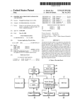
FIG. 1 is a general vieW of the system motor controller
and programming tool.
45
representation of the program to be run by the motor
controller. It is then possible to run through the program for
the motor controller step by step and to folloW the move
FIG. 2 shoWs an eXample of prior art interface betWeen
motor controller and programming tool.
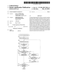
FIG. 3 is a How chart of the programming process.
FIG. 4 is a ?rst vieW shoWing the possible applications of
the motor controller.
ments on the How diagram, thereby checking that the
FIG. 5 is a second vieW shoWing a family of parameters
With a graphic.
FIG. 6 is a third vieW shoWing a time/frequency curve and
a set of family parameters.
sequence is correct. HoWever, Wilson does not deal With the
user interface at the initial set up of the motor controller.
The user interface is typically a hand held terminal With
a screen display or a personal computer, Which is more
comfortable because of the larger vieW. The huge number of
parameters Which can be set up on the frequency converter 55
- in some cases more than 200 combined With the many
FIGS. 7, 8 and 9 shoW the vieWs appearing depending on
the chosen feedback signal.
DESCRIPTION OF AN EXAMPLE EMBODYING
THE BEST MODE OF THE INVENTION
options added to the softWare interface tend to confuse the
operator. Not only has he to memoriZe the parameter num
bers or use time to seek information about them, he is also
FIG. 1 shoWs an overvieW of the system in Which the
confronted on the screen With an abundance of information 60
invention is used. Alaptop or stationary computer (PC) 1 has
and programming choices to be made.
a screen 2, Which displays information concerning set up of
the motor controller 4, in the folloWing teXt called a fre
quency converter. Via a data connection 3, the frequency
converter 4 communicates With the PC 1. The frequency
converter 4 has an I/O module 5 interfacing to the outside
World, and a front panel 6, Which is mounted on the unit
itself. From this panel, the operator is able to program the
SUMMARY OF THE INVENTION
To aid the operator and to improve the user interface, this
invention makes it possible to con?gure the frequency
converter Without knoWing the parameter numbers, or even
Without consulting the user manual. The object of the
65
5,909,372
3
4
unit in nearly the same Way as When using the PC loaded
With set up software. A microprocessor 7 controls the
frequency converter and motor. The set up done by the
operator either from the front panel or from the PC is stored
in an EEPROM 8. Through a driver 9, the microprocessor
controls the activation of the poWer sWitches 10, Which feed
energy in modi?ed form from the mains supply to the
electric motor 12 via line 11. The motor is driving a process
13, and the outcome of this process is fed via line 14 back
to the frequency converter’s I/O-module 5.
Normally, set up of a system like the one shoWn in FIG.
alloW the novice to make a quick set up. Selecting instead
process control 26 means similarly selecting a larger number
of parameters to be set, eg whether the feed back signal is
a voltage, current or pulse signal.
Another feature of the invention is that despite the fact
that the number of parameters is larger When speed control
25 (or process control 26) is selected, the operator Will not
be overWhelmed, because to make the settings the operator
10
1 Would require a person skilled in this speci?c frequency
converter. An abundance of programmable parameters are at
his disposal, Which certainly can be overWhelming to the
novice. FIG. 2 is an example of a prior art interface, and
shoWs a softWare [Siemens Simovis] used for commission
ing a motor controller. The operator has the choice betWeen
15
does not need to knoW the programming parameter numbers.
Instead, set up of the parameters is accomplished in a
more intuitive Way by letting the operator enter in the
physical values from motor and/or process. This is shoWn in
FIG. 5, Which, in this eXample, is the starting vieW the
operator is led through, corresponding to boX 15 of FIG. 3,
regardless of Whether he Wants open loop, speed control or
process control application. Entering in the motor data
Would normally require memoriZing from the operator’s
three control principles, linearly U/f control, quadratic U/f
control and adaptive U/f control. HoWever, independent of
manual parameter number 102 for motor poWer, parameter
number 103 for motor voltage, parameter 104 for motor
frequency, parameter 105 for motor current and parameter
106 for nominal motor speed and then sequentially access
ing these parameters to set them up. According to the
the selection made, in the folloWing vieWs he is confronted
With a large quantity of information and number of settings
to be made. The novice Would have dif?culties in program
ming because he is not informed Which parameters are
invention, instead of presenting the parameter numbers to
necessary to program and Which ones can be programmed.
Even the skilled user Would have to consult the user manual, 25 the operator, Which numbers actually only are of internal
interest to the manufacturers of the frequency converter, the
Which is time consuming and he might even miss some
operator is presented the physical characteristics to be set in
settings, Which are not necessary but could improve the ?nal
control of the motor.
FIG. 3 is a How chart of the programming process. After
the input boXes 27, 28, 29, 30 and 31 (to ease the description,
the parameter numbers are Written in the boXes). This means
entering respectively eg 5 kW, 38 OV, 60 HZ, 13 A and
1500 RPM Without caring about or memoriZing parameter
setting the motor controller to control in “Industry” mode,
Which means speed regulating for eXample a conveyor, the
numbers. This is a more intuitive Way of programming the
frequency converter can be tailored for still more specialiZed
applications. HoWever, providing the motor data 15 and the
ramping times 16 is common to all applications. Therefore,
boXes 15 and 16 could be interchanged or placed later in the
?oWchart. The choice of “HVAC” instead of “Industry”
Would have presented to the operator other parameters and
frequency converter, user friendly and time saving. The
program Which controls the user interface then allocates the
35
setting possibilities, thus shielding him from the less inter
esting options in the “Industry” mode. With “Industry”
selected, the frequency converter must be con?gured to the
desired application in boX 17, Which can be “open loop”
characteriZed by line 18, “speed control” 19 or “process
control” 20. After ?nishing these settings, the type of
reference signals are set in boX 21 and ?nally the eXternal
connections (type of start/stop buttons) are selected in boX
22. Box 23 updates the settings and sends them to the
frequency converter.
According to this invention, instead of presenting all
This can be done in the folloWing Way. The program
allocates an address in the random access memory (RAM) of
the PC to each boX in the vieW. When entering a value in a
boX, the value is Written in the corresponding RAM address.
To the program, this RAM address is knoWn to contain the
setting value of a certain parameter in the frequency con
verter. When all the relevant parameters in the different
vieWs on the PC screen have been set to the desired values,
45
information at one time, a method of programming is
provided in Which the operator is sequentially guided
through the set up, so that only relevant parameters are
displayed in the different vieWs. If a ?rst selection is made
in a vieW, the neXt vieWs only incorporate the parameters
belonging to and relevant to the ?rst selection. FIG. 4 is an
eXample of this, and shoWs a vieW presented on the PC
settings to the right parameter numbers.
a full look up table With parameter settings has been gen
erated in the RAM of the PC. Upon ?nal programming of the
frequency converter (23 in FIG. 3), the PC sends the look up
table and the corresponding parameter numbers via a serial
data link (in FIG. 1) to the EEPROM (8 in FIG. 1) of the
frequency converter.
Yet another aspect of the invention becomes clear, again
referring to FIG. 5. Instead of incorporating in one vieW all
the physical characteristics to be given, only a set of family
parameters are given for each vieW. E.g. parameter numbers
102—106 in the input boXes 27—31 are one set of family
55
parameters, since they all deal With the motor data. Agraphic
screen 2 (FIG. 1) to the operator. In this example, Which
corresponds in sequence to the con?guration boX 17 of FIG.
3, the frequency converter can execute control in three types
32 on FIG. 5 representing a motor symboliZes the contents
of applications: open loop 24 (18 in FIG. 3), speed control
25 (19 in FIG. 3) and process control 26 (20 in FIG. 3). The
family of parameters, because they all deal With ramping
times and motor speed. Here the operator inputs the physical
latter includes PID control, Whereas speed control 25
characteristics of acceleration/deceleration time and maX/
min output frequency of the frequency converter in the
of this family of parameters. Correspondingly, parameter
numbers 200, 201, 207 and 208 in FIG. 6 make up another
involves speed feedback from an encoder or a tachometer.
The simplest mode of control is the open loop. By selecting
this one, the operator in the folloWing vieWs Will only be
presented parameters and choices relevant to this mode of
control; he is shielded from more complicated parameters,
Which only have a function in the other modes. This Will
boXes 33, 34, 35 and 36. Again, after entering the physical
values, the different parameter numbers in the family are set
65
automatically.
Another method according to the invention of entering
these values consists of linking the graphic With the input
5,909,372
5
6
boxes. By pointing on the curve 37 With the computer screen
boxes in dependence on the choices made in box 42 is easily
made. Instead of letting box 43 in FIG. 7 point to the address
in the RAM Where the setting value for parameter number
310 is to be stored, the box 43 in FIG. 9 points to the RAM
address of the parameter number 327.
Various changes can be made to the invention Without
departing from the spirit thereof or scope of the folloWing
claims.
What is claimed is:
pointer and identifying the acceleration points desired, eg
by clicking a computer mouse, the values in the boxes 33—36
Will change correspondingly. This is an easy and intuitive
Way of programming.
The operator has noW been led through a vieW incorpo
rating one set of family parameters concerning motor data
(FIG. 5), another vieW With another set of family parameters
concerning acceleration and deceleration (FIG. 6), and
?nally he has chosen the process control application (FIG.
10
4). In the next vieW, he has to decide on the type of feedback
signal from the process. FIG. 7 shoWs graphics 39 and 40
relating to a set of family parameters, including a curve 41
displaying the relationship betWeen process output and
feedback signal. In the box 42 the operator can choose
guided in vieWs sequentially through the programming
15
betWeen three types of feedback signals, ie voltage signal,
current signal and pulse signal. This corresponds to the step
procedure, the method comprising the steps of:
a) displaying a ?rst vieW With a graphic representation of
modes of application, Where each mode contains a
number of parameters for con?guring the motor
of the reference signal box 21 of FIG. 3.
The folloWing explanation Will describe yet another
aspect of the invention, consisting of the same input box
being used for the programming of several parameter num
bers. By using this method, a high level mode of program
ming the frequency converter is achieved, because the user
interface omits the less interesting control of the frequency
converter and alloWs the operator to get close to process
1. A method of programming a user interface for a motor
controller via a computer incorporating a monitor displaying
different screen displays, Wherein the motor controller is
con?gured by Way of parameters and Where an operator is
25
control in terms he uses. If selecting voltage signal in box
42, the operator has to input ?ve ?gures, Which are maxi
controller, these modes of application indicating basic
control principles to be chosen,
b) selecting one of these modes of application,
c) in the guided vieWs limiting the number of settings and
choices to be chosen by the operator to only contain
parameters from the selected mode of application,
d) Whereby each vieW consists a set of functionally related
parameters in the form of a set of family parameters,
and
mum feedback voltage 43 (“Scale high”), minimum feed
pcs, %) and max and min number of outputs from the
e) incorporating into each vieW graphics relating to the set
of family parameters.
process, 46 and 47. Again, entering data is done by the
operator Without knoWing any parameter numbers. This
controller according to claim 1, Wherein the con?guration is
Would also be the case, if current signal in box 42 Were
done by an operator by means of a keyboard or mouse and
back voltage 44 (“Scale loW”), process unit 45 (eg kg, s,
activated instead of voltage signal. FIG. 8 shoWs this
situation, Where the only difference to the operator is the
change of y-axis labelling to [mA] and the upper limit ?xed
to 20. Internally in the program, hoWever, things have
changed. Where the box 44 “Scale loW” in FIG. 7 Was
tantamount to programming parameter number 309, it is
noW parameter number 315. HoWever, the operator Will not
perceive and is not required to physically enter this change.
In FIG. 9 pulse signal in box 42 has been selected and again,
the y-axis has changed. In the box 43, Where formerly
parameter number 310 Was programmed, is noW parameter
number 327 set. This change of parameter numbers in the
2. Method of programming a user interface for a motor
35
a graphic, Where the graphic is linked With input boxes in the
vieWs, the method comprising sensing selections on a data
representation in the graphic to select setting values for
programming the motor controller, and simultaneously
changing the values in the input boxes so that the selections
in the graphic correspond to the values in the input boxes.
3. Method of programming a user interface for a motor
controller according to claim 1 Wherein the same input
boxes are employed in different screen displays for the
programming of different parameters in the motor controller.
*
*
*
*
*