1
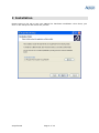
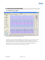
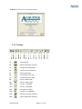
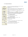
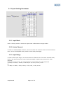
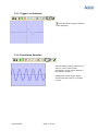
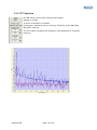
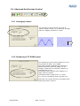
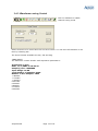
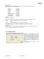
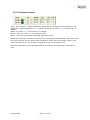
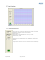
AcquiFlexCM
User Manual
For CM/XM Series
Ref: AcquiFlexCM
V1.0
www.acquitek.com
Copyright © Acquitek. All rights reserved.
Information in this publication supersedes that in all previously published material.
Specifications and price change privileges reserved.
Acquitek, 12 Avenue des Prés, 78180, Montigny le Bretonneux, France
Contacting ACQUITEK
Phone: +33 1 67 37 32 11
Fax: +33 1 67 37 32 13
Address: ACQUITEK SAS.
12 Avenue des Pres
78180 – Montigny le Bretonneux
Web site: www.acquitek.com
Support
Email: [email protected]
AcquiFlexCM
Page 2 of 18
1 Introduction
This manual contains operating information for AcquiFlexCM Software Toolbox.
The manual consists of the following chapters:
1
2
3
Introduction................................................................................................ 3
Installation ................................................................................................. 4
Operating AcquiFlexCM ................................................................................. 5
3.1
Oscilloscope control ............................................................................... 5
3.1.1
Menu ............................................................................................ 6
3.1.2
Toolbar ......................................................................................... 7
3.1.3
Horizontal Selection ........................................................................ 8
3.1.4
Display Channels ............................................................................ 8
3.1.5
Trigger Selection ............................................................................ 8
3.1.6
Vertical Scale Selection .................................................................... 8
3.2
Input Setting Parameter ......................................................................... 9
3.2.1
Input Mode .................................................................................... 9
3.2.2
Active Channel ............................................................................... 9
3.2.3
Input Range................................................................................... 9
3.3
Oscilloscope Display Control .................................................................. 10
3.3.1
Cursor Selection ........................................................................... 10
3.3.2
Zoom Selection ............................................................................ 10
3.3.3
Trigger Line Selection .................................................................... 11
3.3.4
Persistence Selection ..................................................................... 11
3.3.5
FFT Selection ............................................................................... 12
3.4
Advanced Oscilloscope Control............................................................... 13
3.4.1
Averaging Control......................................................................... 13
3.4.2
Streaming to PC RAM control .......................................................... 13
3.4.3
Waveforms saving Control.............................................................. 14
3.5
Autosave Mode ................................................................................... 15
3.6
Waveform Generator ........................................................................... 16
3.6.1
Device & Frequency Control ............................................................ 16
3.6.2
Functions control .......................................................................... 17
3.7
Logic Analyzer .................................................................................... 18
3.7.1
Horizontal Selection ...................................................................... 18
AcquiFlexCM
Page 3 of 18
2 Installation
Please report to the CM or XM User Manual for hardware installation. Once done, just
click on the setup file and follow the process.
AcquiFlexCM
Page 4 of 18
3 Operating AcquiFlexCM
3.1 Oscilloscope control
This figure shows the main Oscilloscope screen.
A maximum of eight channels are display at the same time. User can choose the next
series of eight channels ( if any) by selecting the “Display Channels” ring control.
An information of the current channel number is given at the right top of the screen.
User can move each curve by moving the zero line of the selected channel. To
rearrange all the curves just clic k on the “Reset Pos” button.
AcquiFlexCM
Page 5 of 18
3.1.1 Menu
1
2
3
4
1: File
Exit: Exit from AcquiFlexCM
Load Setup: Load parameters of Oscilloscope, Generator and logical Analyzer
previously save in a *.ini file
Save Setup: Save parameters of Oscilloscope, Generator and logical Analyzer in .ini
file
Note: Each new session of AcquiFlexCM reload the last initialization file , named
AcquiFlexCM.ini and located under [Windows] directory.
2: Instrument
Oscilloscope:
Show Oscilloscope display
Waveform Generator: Show Waveform Generator display
Logic Analyzer:
Show Logic Analyzer display
3: Tools
Autosave mode: See page 15 for details
AcquiFlexCM
Page 6 of 18
4: About: Show Version and Serial Number
3.1.2 Toolbar
1
2
3
4
5
6
7
8
9
10 11
1:
, Print Screen
2:
, Saving selected channel
3:
, Single shot acquisition
4:
, Continuous acquisition
5:
, Stop acquisition
6:
, Horizontal Zoom IN
7:
, Horizontal Zoom OUT
8:
, Zoom Display ON
9:
, Zoom Display OFF
10:
, Cursor 1 ON/OFF
11:
, Cursor 2 ON/OFF
12:
, Persistence Mode
13:
, Trigger Line ON/OFF
14:
, Advanced Scope Setting
15:
, Input Parameter Setting
AcquiFlexCM
12 13
14
Page 7 of 18
15
3.1.3 Horizontal Selection
Device Nb: User can select the logical device number of his board
assigned by Acquitek Control Center software.
Default value = 1
Sample rate programmable from 1S/s up to 1MS/s aggregate , 1Hz
resolution. There is one A/D converter. If 16 channels are active, the
maximum resulting sampling rate is 1MHz /16 = 62500 Hz
Sample size from 2048 samples up to 7999488 samples, modulo 2048
samples.
Pre-trigger mode from 0 up to 32768.
icon available to display
trigger position (ON/OFF). Pre-trigger mode is only available when
Trigger source is an input channel (CH1,…CHn). No pre-trigger
available using Free running mode or External triggering.
3.1.4 Display Channels
Select the eight channel series to display.
3.1.5 Trigger Selection
Select Trigger source, EXT trigger, CH1, CH2, … CHn
NONE means run immediately.
Select Slope Positive or Negative
Select trigger Level
Information on the Trigger Status (Armed, Triggered or Ready)
3.1.6 Vertical Scale Selection
Select Volt per division on all or Selected channel
Reset channel position to default position
AcquiFlexCM
Page 8 of 18
3.2 Input Setting Parameter
3.2.1 Input Mode
Click on binary switch to select the input mode: Differential or Single-Ended
3.2.2 Active Channel
In order to enable/disable channel, user must check the channel item. For those selected
item, click on the ON/OFF binary switch control and press Apply.
3.2.3 Input Range
In order select input range, user must check the channel item. For those selected items,
click on the input range ring control and press Apply. Repeat same process for other
selection.
Depending of CM model, the Vertical Range programmable for each channel is
± 10mV, 0-10mV, ± 100mV, 0-100 mV, ± 1V, 0-1V, ± 10V, 0-10V
Or
± 1.25V, 0-1.25V, ± 2.5V, 0-2.5V, ± 5V, 0-5V, ± 10V, 0-10V
AcquiFlexCM
Page 9 of 18
3.3 Oscilloscope Display Control
3.3.1 Cursor Selection
Two horizontal cursors are available,
attached to the first c hannel only.
The difference between both cursors is
given at the right top corner in black
color.
3.3.2 Zoom Selection
A zoom display is available, cursor
1 and 2 define the portion of curves
displayed.
AcquiFlexCM
Page 10 of 18
3.3.3 Trigger Line Selection
Icon allows the trigger position
to be displayed
3.3.4 Persistence Selection
The Persistence setting allows the
user to control the infinite
persistence of the signal display in
the display Window
Persistence mode allows signal
monitoring and capture of erratic
events
AcquiFlexCM
Page 11 of 18
3.3.5 FFT Selection
FFT ON brings up the multi-channels FFT display.
Display is in dBm
A choice of Windows is included:
Rectangular, Blackman-Harris, Hanning, Hamming, Exact Blackman,
Blackman, Flat top
A cursor allows extracting the frequency and magnitude of a specific
harmonic
AcquiFlexCM
Page 12 of 18
3.4 Advanced Oscilloscope Control
3.4.1 Averaging Control
The averaging control allows the user to
capture many records, up to 256 and average
them for display, default 10 counts
3.4.2 Streaming to PC RAM control
The Streaming control allows capture of very
long stream of data, up to 64MS.
The total number of sample per channel is
64MS/ NumActiveChannel (64MS for one
channel, 32MS for two channels, 8MS for 8
channels and so on).
Decimation factor allows quick display of a
large amount of data
Decimation factor range from 1 to 1000
You can save all data in binary format only
Note that you cannot perform averaging while
streaming mode is active.
AcquiFlexCM
Page 13 of 18
3.4.3 Waveforms saving Control
Click on Diskette to enable
channel saving mode
Select Channel to be saved and click on save button. You can save all channels in one
time by selecting ALL.
The three formats available are asc, dat and awg
*.asc: ASCII
The ASCII file content header with acquisition parameters:
Acquisition on CH1
Date: 11/1/2005 at 16:49:16
Sampling rate: 10000000
Input Range: 10.00
Total Number of Samples: 4096
Number of Pre-Samples: 1024
-0.806641
-0.776367
-0.445312
0.051758
0.532227
0.809570
0.774414
0.443359
AcquiFlexCM
Page 14 of 18
*.dat: Binary
Header information is available at the top of the file, following by the raw data
Information Structure of the Header
{
int Day;
// 4 bytes
int Month;
// 4 bytes
int Year ;
// 4 bytes
int Hour ;
// 4 bytes
int Min ;
// 4 bytes
int Sec ;
// 4 bytes
double iClockRate ; // 8 bytes
double Range ;
// 8 bytes
int Samples ;
// 4 bytes
int pre_Samples ;
// 4 bytes
} Header ;
Header size = 48 bytes
Raw data are signed 16-bit integer. It can take values between –32768 to 32767
-32768
è Minimum value of the current input range
0
è 0V
32767
è Maximum value of the current input range
This binary format is the only one available in Streaming capture.
*.awg: ASCII
Two columns, one column as time information, second column as voltage. This file is
straight compatible with the waveform generators.
3.5 Autosave Mode
Autosave is a very powerful tool for data
transient signals acquisition. It allows
signals monitoring and data capture to disk
with time and date stamping on the trigger
occurrences. The channels are saved to file
using the current hardware configuration
defined in the Oscilloscope instrument.
Waveforms are saved automatically on the
disk in binary or ASCII format, user
selection.
The dialog box allows selection of the
target directory
AcquiFlexCM
Page 15 of 18
3.6 Waveform Generator
3.6.1 Device & Frequency Control
Device Nb: User can select the logical device number of his board
assigned by Acquitek Control Center software.
Default value = 1
Output frequency is programmable from 0.01Hz up to 500kHz
AcquiFlexCM
Page 16 of 18
3.6.2 Functions control
Type: Sine, Square, Triangle, Sawtooth, White Noise, DC and arbitrary Waveform File
Amplitude: Output amplitude is +/- selected value into 50 Ohms, +/ -5V maximum, 1V
default
Offset: DC value, +/- 5V maximum, 0V default
Phase: -360° to +360°, 0° is the default value
Noise: Add 10% of selected amplitude with white noise
When File wavetype is chosen, selects the file containing waveform data. Each line of the
file should contain a time offset value followed by a tab, then the sample value in volt
and a carriage return. The number of samples must be a multiple of 32.
Press the ON button of the selected channel to generate the waveform. Press OFF to
stop.
AcquiFlexCM
Page 17 of 18
3.7 Logic Analyzer
3.7.1 Horizontal Selection
Device Nb: User can select the logical device number of his board
assigned by Acquitek Control Center software.
Default value = 1
Sample Rate is programmable from 1Hz up to 1 MHz
Default value, 1 MHz
Sample size from 2048 samples up to 1MSamples, modulo 2048
samples.
Logic Analyzer cannot be use in the same time as the oscilloscope
AcquiFlexCM
Page 18 of 18